EP0429424A1 - Elément de construction - Google Patents
Elément de construction Download PDFInfo
- Publication number
- EP0429424A1 EP0429424A1 EP90850379A EP90850379A EP0429424A1 EP 0429424 A1 EP0429424 A1 EP 0429424A1 EP 90850379 A EP90850379 A EP 90850379A EP 90850379 A EP90850379 A EP 90850379A EP 0429424 A1 EP0429424 A1 EP 0429424A1
- Authority
- EP
- European Patent Office
- Prior art keywords
- strips
- board
- boards
- plates
- reinforceing
- Prior art date
- Legal status (The legal status is an assumption and is not a legal conclusion. Google has not performed a legal analysis and makes no representation as to the accuracy of the status listed.)
- Withdrawn
Links
- 238000005452 bending Methods 0.000 claims abstract description 15
- 239000000463 material Substances 0.000 claims abstract description 15
- 230000002787 reinforcement Effects 0.000 claims abstract description 6
- 239000002023 wood Substances 0.000 claims description 13
- 239000003292 glue Substances 0.000 claims description 9
- 238000004519 manufacturing process Methods 0.000 claims description 5
- 238000000034 method Methods 0.000 claims description 4
- 230000006835 compression Effects 0.000 claims 1
- 238000007906 compression Methods 0.000 claims 1
- 230000002596 correlated effect Effects 0.000 claims 1
- 239000011521 glass Substances 0.000 claims 1
- 238000003825 pressing Methods 0.000 claims 1
- 239000003365 glass fiber Substances 0.000 abstract description 2
- 238000003754 machining Methods 0.000 abstract 1
- 238000010276 construction Methods 0.000 description 3
- 238000004026 adhesive bonding Methods 0.000 description 2
- 238000005520 cutting process Methods 0.000 description 1
- 238000003892 spreading Methods 0.000 description 1
Images



Classifications
-
- E—FIXED CONSTRUCTIONS
- E04—BUILDING
- E04C—STRUCTURAL ELEMENTS; BUILDING MATERIALS
- E04C2/00—Building elements of relatively thin form for the construction of parts of buildings, e.g. sheet materials, slabs, or panels
- E04C2/02—Building elements of relatively thin form for the construction of parts of buildings, e.g. sheet materials, slabs, or panels characterised by specified materials
- E04C2/26—Building elements of relatively thin form for the construction of parts of buildings, e.g. sheet materials, slabs, or panels characterised by specified materials composed of materials covered by two or more of groups E04C2/04, E04C2/08, E04C2/10 or of materials covered by one of these groups with a material not specified in one of the groups
-
- E—FIXED CONSTRUCTIONS
- E04—BUILDING
- E04C—STRUCTURAL ELEMENTS; BUILDING MATERIALS
- E04C2/00—Building elements of relatively thin form for the construction of parts of buildings, e.g. sheet materials, slabs, or panels
- E04C2/30—Building elements of relatively thin form for the construction of parts of buildings, e.g. sheet materials, slabs, or panels characterised by the shape or structure
- E04C2/34—Building elements of relatively thin form for the construction of parts of buildings, e.g. sheet materials, slabs, or panels characterised by the shape or structure composed of two or more spaced sheet-like parts
- E04C2/3405—Building elements of relatively thin form for the construction of parts of buildings, e.g. sheet materials, slabs, or panels characterised by the shape or structure composed of two or more spaced sheet-like parts spaced apart by profiled spacer sheets
-
- E—FIXED CONSTRUCTIONS
- E04—BUILDING
- E04C—STRUCTURAL ELEMENTS; BUILDING MATERIALS
- E04C2/00—Building elements of relatively thin form for the construction of parts of buildings, e.g. sheet materials, slabs, or panels
- E04C2/30—Building elements of relatively thin form for the construction of parts of buildings, e.g. sheet materials, slabs, or panels characterised by the shape or structure
- E04C2/34—Building elements of relatively thin form for the construction of parts of buildings, e.g. sheet materials, slabs, or panels characterised by the shape or structure composed of two or more spaced sheet-like parts
- E04C2/3405—Building elements of relatively thin form for the construction of parts of buildings, e.g. sheet materials, slabs, or panels characterised by the shape or structure composed of two or more spaced sheet-like parts spaced apart by profiled spacer sheets
- E04C2002/3444—Corrugated sheets
- E04C2002/345—Corrugated sheets with triangular corrugations
-
- E—FIXED CONSTRUCTIONS
- E04—BUILDING
- E04C—STRUCTURAL ELEMENTS; BUILDING MATERIALS
- E04C2/00—Building elements of relatively thin form for the construction of parts of buildings, e.g. sheet materials, slabs, or panels
- E04C2/30—Building elements of relatively thin form for the construction of parts of buildings, e.g. sheet materials, slabs, or panels characterised by the shape or structure
- E04C2/34—Building elements of relatively thin form for the construction of parts of buildings, e.g. sheet materials, slabs, or panels characterised by the shape or structure composed of two or more spaced sheet-like parts
- E04C2002/3494—Apparatus for making profiled spacer sheets
Definitions
- This invention is concerned with building elements and in particular supporting elements or rafters and walls in houses.
- wood is still one of the most commonly used materials, small houses in general, but in particular for roof constructions for instance cross bars and girders in rafters.
- Wood is however continuosly becoming more costly to use and alternative solutions in the shape of board beams etc. has been invented, constituted by board and wood. Regretfully however these solutions tend to be more expensive than one would expect when considering the differences in material costs. The reason for this is an increased cost for manual work.
- the solution to this problem is in accordance with the invention to use board or a similar sheet like material sandwiched together by distance elements which are also made from board material or a similar sheet material.
- the distance elements are before the connection to the outer boards so shaped that triangular structures arise.
- These triangular structures can take different shapes. For instance it can be constituted by a lengthwise folded strip of board that along the apex and elongate foot strips is glued to different boards or a zig-zag bent sheet with apexes in contact with the outer board sheets.
- the intermediate distance strips can be constituted by zigzag folded board strips or of course some other suitable material, glued, welded or in some other way fastened to the board sheets.
- the board material can be forceably compressed at the intended bending line.
- the board material is reinforced by threads, wires, webs etc. fabricated from for instance plastic or glass fibre and running perpendicular to the bending lines.
- reinforcement prevents in cooperation with a precompressing of the board material this from breaking entirely apart when it is bent to its final shape.
- zigzag bent board strips these can preferably be placed perpendicular to the two boards constituting the sides of a building element. In this way the width of the strip will define the distance between the sides of the building element.
- the achieved structure can either be used immediately to shape for instance wall elements by locating edge reinforcements in the shape of wood. This is preferably done by placeing the zigzag bent strips and the wood edges on a lower board, then placeing an upper board upon this and then glueing everything together in a fixture.
- Another way to operate is however to use the fabricated elements to make strong supporting structures that are not rektangular by cutting up the laminated structure in the desired shape and then providing it with reinforceing wood edges, that in most cases also are necessary in order to allow fastening by means of nails.
- the supporting characteristics of the element in accordance with the invention can be varied by varying the distance between the distance elements in their lateral spreading over the building element.
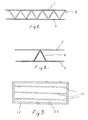
- fig 1 shows a first embodiment of a supporting element according to the invention
- fig 2 a second embodiment in cross-section
- fig 3 a third embodiment in a longitudinal section
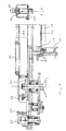
- fig 4 a machinery for the fabrication of the element of fig 3
- figs 5 and 6 a part of the the machinery shown in fig 4 seen from the side and above respectively
- fig 7 a detail of this part of the machinery in a cross-section
- fig 8 the part of the machinery depicted in fig 7 seen from above
- fig 9 a further detail of the part of the machinery shown in fig 6 in cross-section.
- the element in fig 1 encludes reinforceing zig-zag bent board layer 3 between two boards 1 and 2, connected by glueing the apexes of the zig-zag layer 3 to the outer boards.
- the element is constituted by two outer boards 4 and 5 that are connected by essentially V-shaped profiles 6 made of bent board material.
- a building element is constituted by zig-zag bent reinforceing strips 10 placed between two boards of which only the lower 22 is shown.
- the invented machinery shown in figs 4-9 is intended for the fabrication of building elements of the type shown in fig 3 and includes two transporting roller tables 11 and 12 and between these a strip position in station 13 and a glue press 14.
- framelike fixtures 18 circulate.
- the fixtures are precisely so large that they can receive at the location A, a lower board 22, the upper side of which is provided with glue or the like and wood edge reinforceing members 17 placed along the edges.
- Framelike fixture 18 is then stepwise displaced laterally (arrow B) so that the station 13 with in consecutive steps can drop zig-zag bent reinforceing strips 10 on the lower board 22 that lies in one of the fixtures 18 is moved on the rolls 15 by a step drive 37 laterally towards the other roller table 11.
- the strips 10 are fed into a chute 24 extending along the station and out over fixture and lower board and when the en-tire strip 10 in in place in the chute the strip is released 15 and pressed 16 down against the lower board 22 in the fixture 18.
- the zigzag shaped distance_ and reinforceing element or strip 10 has been given its zigzag form by being fed between and past two toothed rollers 30 and 31. From these the strip is fed into the chute 24 by an endless belt conveyor 27 gripping the strip from above and pushing the strip into the chute 24 simultaneous with its continued shapeing between the toothed rollers.
- the strips are consecutively taken from a magazine 29 of strips 10 cut to the correct length.
- the magazine can be heated so that the strips 10 adhere to the underlying glue coated board 22 almost immediately. In this way the reinforceing strips will lie still as the fixture 18 is transported stepwise 19 laterally.
- the stiffning or reinforcement strips are dropped in a number corresponding to the need of stiffness in the ready sandwhich element.
- the strips Before the strips enter between the toothed rollers 30, 31 they are preconditioned for bending by being compressed between two rollers 32 provided with protruding edges which compress the strip at the intended bending lines. As shown only one side at a time is compressed, but preferably compressing edges on both sides cooperate at each bending line since this gives a better result. These two rollers are driven with a speed that is related to that of the toothed rollers to get the desired bending. After the rollers 30 and 31 a prebending piston 34 can be arranged, bending the first end 101 of each strip so that its entrance between the toothed rollers will be correct.
- the toothed rollers have covering disks 23 securing that the strips when zigzag bent do not try to escape upwards. Also the following belt conveyor 27 and the pushing out element 35 in the chute extending over the entire length of the chute prevents this.
- the distance between the preconditioning rollers 32 and the toothed rollers 30, 31 is adjusteable so that correct bending conditions is secured.
- the strip reinforcement by threads also increase the resilience of the strip so that these when disposed on the lower board can expand logintudinally to contact with the wood edges.
Landscapes
- Engineering & Computer Science (AREA)
- Architecture (AREA)
- Civil Engineering (AREA)
- Structural Engineering (AREA)
Applications Claiming Priority (4)
| Application Number | Priority Date | Filing Date | Title |
|---|---|---|---|
| SE8903892A SE8903892L (en) | 1989-11-21 | 1989-11-21 | Building element - has two boards with zigzag shaped distance element between and strips of similar material bent to this shape |
| SE8903892 | 1989-11-21 | ||
| SE8904011 | 1989-11-28 | ||
| SE8904011A SE8904011L (en) | 1989-11-28 | 1989-11-28 | Building element - has two boards with zigzag shaped distance element between and strips of similar material bent to this shape |
Publications (1)
| Publication Number | Publication Date |
|---|---|
| EP0429424A1 true EP0429424A1 (fr) | 1991-05-29 |
Family
ID=26660642
Family Applications (1)
| Application Number | Title | Priority Date | Filing Date |
|---|---|---|---|
| EP90850379A Withdrawn EP0429424A1 (fr) | 1989-11-21 | 1990-11-20 | Elément de construction |
Country Status (1)
| Country | Link |
|---|---|
| EP (1) | EP0429424A1 (fr) |
Citations (5)
| Publication number | Priority date | Publication date | Assignee | Title |
|---|---|---|---|---|
| FR909446A (fr) * | 1943-09-03 | 1946-05-08 | Jonkopings Och Vulcans Tandsti | Perfectionnements aux planches lamellées |
| FR1564962A (fr) * | 1968-03-08 | 1969-04-25 | ||
| FR1578060A (fr) * | 1968-05-13 | 1969-08-14 | ||
| GB1281686A (en) * | 1968-09-04 | 1972-07-12 | Susanne Klara Atteck | Method of making a structural material |
| FR2556024A1 (fr) * | 1983-12-05 | 1985-06-07 | Sge Construction | Composants de construction plats pour batiments |
-
1990
- 1990-11-20 EP EP90850379A patent/EP0429424A1/fr not_active Withdrawn
Patent Citations (5)
| Publication number | Priority date | Publication date | Assignee | Title |
|---|---|---|---|---|
| FR909446A (fr) * | 1943-09-03 | 1946-05-08 | Jonkopings Och Vulcans Tandsti | Perfectionnements aux planches lamellées |
| FR1564962A (fr) * | 1968-03-08 | 1969-04-25 | ||
| FR1578060A (fr) * | 1968-05-13 | 1969-08-14 | ||
| GB1281686A (en) * | 1968-09-04 | 1972-07-12 | Susanne Klara Atteck | Method of making a structural material |
| FR2556024A1 (fr) * | 1983-12-05 | 1985-06-07 | Sge Construction | Composants de construction plats pour batiments |
Similar Documents
| Publication | Publication Date | Title |
|---|---|---|
| US4336678A (en) | I-Beam truss structure | |
| US5852908A (en) | Structural beam and web | |
| US7077988B2 (en) | Corrugated fiberboard panels for use in the construction of walls, ceilings and floors | |
| US4160350A (en) | Floor joist plate | |
| EP0796641A1 (fr) | Piste de roulement, pièces d'assemblage de celle-ci et procédé de fabrication de ces pièces | |
| AU728924B2 (en) | Lintel | |
| US20050074587A1 (en) | Wall element | |
| US4428792A (en) | Method of forming a structural column | |
| US3785277A (en) | Apparatus and method for making trusses | |
| CA2626838A1 (fr) | Procede de fabrication de panneau cellulaire, panneau cellulaire, procede de fabrication d'element de panneau cellulaire de bande plate d'acier, et chaine de fabrication | |
| US20020064629A1 (en) | Corrugated cardboard plates, method of and apparatus for making the same | |
| US3813842A (en) | Laminated, variable density, structural wood products and method for making the same | |
| US4005520A (en) | Frame structure fabricating system | |
| EP0203063A1 (fr) | Fabrication de produits de bois reconsolide. | |
| US4241557A (en) | Construction member and plate therefor | |
| EP0004086B1 (fr) | Matériau isolant lamellé en forme de plaque et son procédé de fabrication | |
| CA2167404A1 (fr) | Panneau de laine minerale et methode de fabrication dudit panneau | |
| EP0396306A3 (fr) | Ame pour panneau sandwich | |
| EP0429424A1 (fr) | Elément de construction | |
| US5609557A (en) | Paper pallet with an immproved configuration | |
| US3686809A (en) | Reinforced wood floor sections | |
| FI93890B (fi) | Menetelmä ja laite puristettavan vyöhykkeen muodostamiseksi lämpöä, ääntä ja/tai tulta eristävän mineraalikuitulevyn tai -radan reuna-alueelle | |
| US3868898A (en) | Rolling truss joint connector plates | |
| EP1180564A1 (fr) | Elément de paroi en cellulose | |
| US20070151488A1 (en) | Cardboard pallet |
Legal Events
| Date | Code | Title | Description |
|---|---|---|---|
| PUAI | Public reference made under article 153(3) epc to a published international application that has entered the european phase |
Free format text: ORIGINAL CODE: 0009012 |
|
| AK | Designated contracting states |
Kind code of ref document: A1 Designated state(s): AT BE CH DE DK ES FR GB GR IT LI LU NL SE |
|
| 17P | Request for examination filed |
Effective date: 19911105 |
|
| 17Q | First examination report despatched |
Effective date: 19920723 |
|
| STAA | Information on the status of an ep patent application or granted ep patent |
Free format text: STATUS: THE APPLICATION IS DEEMED TO BE WITHDRAWN |
|
| 18D | Application deemed to be withdrawn |
Effective date: 19921203 |
|
| K1C1 | Correction of patent application (title page) published |
Effective date: 19910529 |