EP0429425B1 - Gaszylinder mit verbesserten Mischungseigenschaften - Google Patents
Gaszylinder mit verbesserten Mischungseigenschaften Download PDFInfo
- Publication number
- EP0429425B1 EP0429425B1 EP90870213A EP90870213A EP0429425B1 EP 0429425 B1 EP0429425 B1 EP 0429425B1 EP 90870213 A EP90870213 A EP 90870213A EP 90870213 A EP90870213 A EP 90870213A EP 0429425 B1 EP0429425 B1 EP 0429425B1
- Authority
- EP
- European Patent Office
- Prior art keywords
- gas
- tube
- cylinder
- gas mixture
- cylinder shell
- Prior art date
- Legal status (The legal status is an assumption and is not a legal conclusion. Google has not performed a legal analysis and makes no representation as to the accuracy of the status listed.)
- Expired - Lifetime
Links
Images
Classifications
-
- F—MECHANICAL ENGINEERING; LIGHTING; HEATING; WEAPONS; BLASTING
- F17—STORING OR DISTRIBUTING GASES OR LIQUIDS
- F17C—VESSELS FOR CONTAINING OR STORING COMPRESSED, LIQUEFIED OR SOLIDIFIED GASES; FIXED-CAPACITY GAS-HOLDERS; FILLING VESSELS WITH, OR DISCHARGING FROM VESSELS, COMPRESSED, LIQUEFIED, OR SOLIDIFIED GASES
- F17C5/00—Methods or apparatus for filling containers with liquefied, solidified, or compressed gases under pressures
- F17C5/06—Methods or apparatus for filling containers with liquefied, solidified, or compressed gases under pressures for filling with compressed gases
-
- F—MECHANICAL ENGINEERING; LIGHTING; HEATING; WEAPONS; BLASTING
- F17—STORING OR DISTRIBUTING GASES OR LIQUIDS
- F17C—VESSELS FOR CONTAINING OR STORING COMPRESSED, LIQUEFIED OR SOLIDIFIED GASES; FIXED-CAPACITY GAS-HOLDERS; FILLING VESSELS WITH, OR DISCHARGING FROM VESSELS, COMPRESSED, LIQUEFIED, OR SOLIDIFIED GASES
- F17C7/00—Methods or apparatus for discharging liquefied, solidified, or compressed gases from pressure vessels, not covered by another subclass
-
- F—MECHANICAL ENGINEERING; LIGHTING; HEATING; WEAPONS; BLASTING
- F17—STORING OR DISTRIBUTING GASES OR LIQUIDS
- F17C—VESSELS FOR CONTAINING OR STORING COMPRESSED, LIQUEFIED OR SOLIDIFIED GASES; FIXED-CAPACITY GAS-HOLDERS; FILLING VESSELS WITH, OR DISCHARGING FROM VESSELS, COMPRESSED, LIQUEFIED, OR SOLIDIFIED GASES
- F17C2201/00—Vessel construction, in particular geometry, arrangement or size
- F17C2201/01—Shape
- F17C2201/0104—Shape cylindrical
- F17C2201/0109—Shape cylindrical with exteriorly curved end-piece
-
- F—MECHANICAL ENGINEERING; LIGHTING; HEATING; WEAPONS; BLASTING
- F17—STORING OR DISTRIBUTING GASES OR LIQUIDS
- F17C—VESSELS FOR CONTAINING OR STORING COMPRESSED, LIQUEFIED OR SOLIDIFIED GASES; FIXED-CAPACITY GAS-HOLDERS; FILLING VESSELS WITH, OR DISCHARGING FROM VESSELS, COMPRESSED, LIQUEFIED, OR SOLIDIFIED GASES
- F17C2201/00—Vessel construction, in particular geometry, arrangement or size
- F17C2201/01—Shape
- F17C2201/0104—Shape cylindrical
- F17C2201/0119—Shape cylindrical with flat end-piece
-
- F—MECHANICAL ENGINEERING; LIGHTING; HEATING; WEAPONS; BLASTING
- F17—STORING OR DISTRIBUTING GASES OR LIQUIDS
- F17C—VESSELS FOR CONTAINING OR STORING COMPRESSED, LIQUEFIED OR SOLIDIFIED GASES; FIXED-CAPACITY GAS-HOLDERS; FILLING VESSELS WITH, OR DISCHARGING FROM VESSELS, COMPRESSED, LIQUEFIED, OR SOLIDIFIED GASES
- F17C2201/00—Vessel construction, in particular geometry, arrangement or size
- F17C2201/03—Orientation
- F17C2201/032—Orientation with substantially vertical main axis
-
- F—MECHANICAL ENGINEERING; LIGHTING; HEATING; WEAPONS; BLASTING
- F17—STORING OR DISTRIBUTING GASES OR LIQUIDS
- F17C—VESSELS FOR CONTAINING OR STORING COMPRESSED, LIQUEFIED OR SOLIDIFIED GASES; FIXED-CAPACITY GAS-HOLDERS; FILLING VESSELS WITH, OR DISCHARGING FROM VESSELS, COMPRESSED, LIQUEFIED, OR SOLIDIFIED GASES
- F17C2203/00—Vessel construction, in particular walls or details thereof
- F17C2203/06—Materials for walls or layers thereof; Properties or structures of walls or their materials
- F17C2203/0634—Materials for walls or layers thereof
- F17C2203/0636—Metals
- F17C2203/0639—Steels
-
- F—MECHANICAL ENGINEERING; LIGHTING; HEATING; WEAPONS; BLASTING
- F17—STORING OR DISTRIBUTING GASES OR LIQUIDS
- F17C—VESSELS FOR CONTAINING OR STORING COMPRESSED, LIQUEFIED OR SOLIDIFIED GASES; FIXED-CAPACITY GAS-HOLDERS; FILLING VESSELS WITH, OR DISCHARGING FROM VESSELS, COMPRESSED, LIQUEFIED, OR SOLIDIFIED GASES
- F17C2205/00—Vessel construction, in particular mounting arrangements, attachments or identifications means
- F17C2205/03—Fluid connections, filters, valves, closure means or other attachments
- F17C2205/0302—Fittings, valves, filters, or components in connection with the gas storage device
- F17C2205/0323—Valves
- F17C2205/0329—Valves manually actuated
-
- F—MECHANICAL ENGINEERING; LIGHTING; HEATING; WEAPONS; BLASTING
- F17—STORING OR DISTRIBUTING GASES OR LIQUIDS
- F17C—VESSELS FOR CONTAINING OR STORING COMPRESSED, LIQUEFIED OR SOLIDIFIED GASES; FIXED-CAPACITY GAS-HOLDERS; FILLING VESSELS WITH, OR DISCHARGING FROM VESSELS, COMPRESSED, LIQUEFIED, OR SOLIDIFIED GASES
- F17C2205/00—Vessel construction, in particular mounting arrangements, attachments or identifications means
- F17C2205/03—Fluid connections, filters, valves, closure means or other attachments
- F17C2205/0388—Arrangement of valves, regulators, filters
- F17C2205/0394—Arrangement of valves, regulators, filters in direct contact with the pressure vessel
-
- F—MECHANICAL ENGINEERING; LIGHTING; HEATING; WEAPONS; BLASTING
- F17—STORING OR DISTRIBUTING GASES OR LIQUIDS
- F17C—VESSELS FOR CONTAINING OR STORING COMPRESSED, LIQUEFIED OR SOLIDIFIED GASES; FIXED-CAPACITY GAS-HOLDERS; FILLING VESSELS WITH, OR DISCHARGING FROM VESSELS, COMPRESSED, LIQUEFIED, OR SOLIDIFIED GASES
- F17C2221/00—Handled fluid, in particular type of fluid
- F17C2221/01—Pure fluids
- F17C2221/011—Oxygen
-
- F—MECHANICAL ENGINEERING; LIGHTING; HEATING; WEAPONS; BLASTING
- F17—STORING OR DISTRIBUTING GASES OR LIQUIDS
- F17C—VESSELS FOR CONTAINING OR STORING COMPRESSED, LIQUEFIED OR SOLIDIFIED GASES; FIXED-CAPACITY GAS-HOLDERS; FILLING VESSELS WITH, OR DISCHARGING FROM VESSELS, COMPRESSED, LIQUEFIED, OR SOLIDIFIED GASES
- F17C2221/00—Handled fluid, in particular type of fluid
- F17C2221/01—Pure fluids
- F17C2221/012—Hydrogen
-
- F—MECHANICAL ENGINEERING; LIGHTING; HEATING; WEAPONS; BLASTING
- F17—STORING OR DISTRIBUTING GASES OR LIQUIDS
- F17C—VESSELS FOR CONTAINING OR STORING COMPRESSED, LIQUEFIED OR SOLIDIFIED GASES; FIXED-CAPACITY GAS-HOLDERS; FILLING VESSELS WITH, OR DISCHARGING FROM VESSELS, COMPRESSED, LIQUEFIED, OR SOLIDIFIED GASES
- F17C2221/00—Handled fluid, in particular type of fluid
- F17C2221/01—Pure fluids
- F17C2221/013—Carbon dioxide
-
- F—MECHANICAL ENGINEERING; LIGHTING; HEATING; WEAPONS; BLASTING
- F17—STORING OR DISTRIBUTING GASES OR LIQUIDS
- F17C—VESSELS FOR CONTAINING OR STORING COMPRESSED, LIQUEFIED OR SOLIDIFIED GASES; FIXED-CAPACITY GAS-HOLDERS; FILLING VESSELS WITH, OR DISCHARGING FROM VESSELS, COMPRESSED, LIQUEFIED, OR SOLIDIFIED GASES
- F17C2221/00—Handled fluid, in particular type of fluid
- F17C2221/01—Pure fluids
- F17C2221/016—Noble gases (Ar, Kr, Xe)
-
- F—MECHANICAL ENGINEERING; LIGHTING; HEATING; WEAPONS; BLASTING
- F17—STORING OR DISTRIBUTING GASES OR LIQUIDS
- F17C—VESSELS FOR CONTAINING OR STORING COMPRESSED, LIQUEFIED OR SOLIDIFIED GASES; FIXED-CAPACITY GAS-HOLDERS; FILLING VESSELS WITH, OR DISCHARGING FROM VESSELS, COMPRESSED, LIQUEFIED, OR SOLIDIFIED GASES
- F17C2221/00—Handled fluid, in particular type of fluid
- F17C2221/01—Pure fluids
- F17C2221/016—Noble gases (Ar, Kr, Xe)
- F17C2221/017—Helium
-
- F—MECHANICAL ENGINEERING; LIGHTING; HEATING; WEAPONS; BLASTING
- F17—STORING OR DISTRIBUTING GASES OR LIQUIDS
- F17C—VESSELS FOR CONTAINING OR STORING COMPRESSED, LIQUEFIED OR SOLIDIFIED GASES; FIXED-CAPACITY GAS-HOLDERS; FILLING VESSELS WITH, OR DISCHARGING FROM VESSELS, COMPRESSED, LIQUEFIED, OR SOLIDIFIED GASES
- F17C2221/00—Handled fluid, in particular type of fluid
- F17C2221/03—Mixtures
-
- F—MECHANICAL ENGINEERING; LIGHTING; HEATING; WEAPONS; BLASTING
- F17—STORING OR DISTRIBUTING GASES OR LIQUIDS
- F17C—VESSELS FOR CONTAINING OR STORING COMPRESSED, LIQUEFIED OR SOLIDIFIED GASES; FIXED-CAPACITY GAS-HOLDERS; FILLING VESSELS WITH, OR DISCHARGING FROM VESSELS, COMPRESSED, LIQUEFIED, OR SOLIDIFIED GASES
- F17C2223/00—Handled fluid before transfer, i.e. state of fluid when stored in the vessel or before transfer from the vessel
- F17C2223/01—Handled fluid before transfer, i.e. state of fluid when stored in the vessel or before transfer from the vessel characterised by the phase
- F17C2223/0146—Two-phase
- F17C2223/0153—Liquefied gas, e.g. LPG, GPL
-
- F—MECHANICAL ENGINEERING; LIGHTING; HEATING; WEAPONS; BLASTING
- F17—STORING OR DISTRIBUTING GASES OR LIQUIDS
- F17C—VESSELS FOR CONTAINING OR STORING COMPRESSED, LIQUEFIED OR SOLIDIFIED GASES; FIXED-CAPACITY GAS-HOLDERS; FILLING VESSELS WITH, OR DISCHARGING FROM VESSELS, COMPRESSED, LIQUEFIED, OR SOLIDIFIED GASES
- F17C2223/00—Handled fluid before transfer, i.e. state of fluid when stored in the vessel or before transfer from the vessel
- F17C2223/03—Handled fluid before transfer, i.e. state of fluid when stored in the vessel or before transfer from the vessel characterised by the pressure level
- F17C2223/036—Very high pressure (>80 bar)
-
- F—MECHANICAL ENGINEERING; LIGHTING; HEATING; WEAPONS; BLASTING
- F17—STORING OR DISTRIBUTING GASES OR LIQUIDS
- F17C—VESSELS FOR CONTAINING OR STORING COMPRESSED, LIQUEFIED OR SOLIDIFIED GASES; FIXED-CAPACITY GAS-HOLDERS; FILLING VESSELS WITH, OR DISCHARGING FROM VESSELS, COMPRESSED, LIQUEFIED, OR SOLIDIFIED GASES
- F17C2223/00—Handled fluid before transfer, i.e. state of fluid when stored in the vessel or before transfer from the vessel
- F17C2223/04—Handled fluid before transfer, i.e. state of fluid when stored in the vessel or before transfer from the vessel characterised by other properties of handled fluid before transfer
- F17C2223/042—Localisation of the removal point
- F17C2223/046—Localisation of the removal point in the liquid
- F17C2223/047—Localisation of the removal point in the liquid with a dip tube
-
- Y—GENERAL TAGGING OF NEW TECHNOLOGICAL DEVELOPMENTS; GENERAL TAGGING OF CROSS-SECTIONAL TECHNOLOGIES SPANNING OVER SEVERAL SECTIONS OF THE IPC; TECHNICAL SUBJECTS COVERED BY FORMER USPC CROSS-REFERENCE ART COLLECTIONS [XRACs] AND DIGESTS
- Y02—TECHNOLOGIES OR APPLICATIONS FOR MITIGATION OR ADAPTATION AGAINST CLIMATE CHANGE
- Y02E—REDUCTION OF GREENHOUSE GAS [GHG] EMISSIONS, RELATED TO ENERGY GENERATION, TRANSMISSION OR DISTRIBUTION
- Y02E60/00—Enabling technologies; Technologies with a potential or indirect contribution to GHG emissions mitigation
- Y02E60/30—Hydrogen technology
- Y02E60/32—Hydrogen storage
Definitions
- This invention relates generally to containers, i.e. cylinders, for the storage, transport or delivery of gas, and more particularly to the field of cylinders for use with gas mixtures.
- Cylinders generally have a cylindrical shape, i.e. a generally circular cross-section with one long axis perpendicular to the circular cross-section. Cylinders are often positioned with the long axis vertically oriented when they are used to store, transport or deliver gas.
- a problem which arises when gas mixtures are used with cylinders is the stratification of individual components of the gas mixture, especially when the individual components have significantly differing densities.
- a cylinder is generally filled first with one component of the gas mixture and then with the second component. If the gas mixture has three or more components, each subsequent component is sequentially charged into the cylinder. The charging is generally carried out through a valve located at the neck or narrowed portion of the cylinder. The sequential charging of each gas mixture component to the cylinder contributes to an initial stratification of the individual gas mixture components. Furthermore, if the cylinder remains in a single position for a length of time, the stratification proceeds further as gas components of differing densities preferentially rise or fall within the cylinder.
- the stratification is generally not complete; there is some of each component in all parts of the cylinder.
- the stratification results in the cylinder having a gas mixture richer in the lighter component or components in the upper portion of the cylinder than what the gas mixture specification calls for, and a gas mixture richer in the heavier component or components in the lower portion of the cylinder than what the gas mixture specification calls for.
- This stratification may cause significant quality and other problems because it causes a gas mixture to be delivered from the cylinder which deviates from the gas mixture specifications. This is a particular problem in certain applications such as in welding where even a small deviation from the shielding gas specification may have a significant impact on weld quality.
- the new high pressure cylinder would exacerbate the problem of pure gas component in a tube because the tube would be filled with pure component at much high pressure, thus taking longer to clear the tube of pure component and begin delivery of the specified gas mixture. Accordingly, wastage would be increased serving to negate some of the advantage attainable with the high pressure cylinder.
- US 4 611 641 discloses a cylinder for the storage of gas mixtures comprising a valve and a tube, which is provided with a series of holes. Gas will be drawn from the cylinder, through the holes, into the tube and out of the valve.
- DE 2 028 463 and US 1 938 036 both disclose methods for removing gas/liquid mixtures from pressure vessels, which vessels are provided with a tube and one or more holes, through which, during delivery, the fluid will flow out.
- a method for delivering gas from a cylinder comprising:
- cylinder means any vessel for the containment of gas at pressure and is not intended to be limited to vessels having a cylindrical configuration.
- gas means any fluid which acts to occupy the whole of any container within which it is put.
- the invention may be used with any gas or gas mixture.
- the invention will find its greatest utility with a gas mixture in which the individual components of the gas mixture tend to stratify due to, for example, differences in density.
- a great variety of such gas mixtures exist, among which one can name mixtures of argon and carbon dioxide, mixtures of argon, carbon dioxide and helium, and mixtures of argon, carbon dioxide and oxygen.
- Gas mixtures which contain carbon dioxide are particularly prone to stratification due to the higher relative weight of carbon dioxide to that of most other gases.
- gas mixtures which contain hydrogen or helium are also particularly prone to stratification due to the lower relative weight of hydrogen and helium to that of other gases.
- gases which are classified as liquified compressed gases are prone to stratification at temperatures below their dew point.
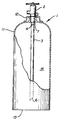
- cylinder 1 comprises cylinder shell 11 which, in the embodiment illustrated in the Figure has a generally cylindrical shape. Any other effective shape, such as a sphere or horizontally oriented tank of circular or non-circular cross-section, may also be employed for the cylinder shell.
- the cylinder shell is made out of any effective material such as steel.
- the cylinder of this invention also includes valve means through which gas is passed into and out of the cylinder shell interior, i.e. the space within the cylinder shell.
- valve means through which gas is passed into and out of the cylinder shell interior, i.e. the space within the cylinder shell.
- Those skilled in the art are familiar with the valves which are conventionally used with gas cylinder operation. Among such valve types one can name pressure sealed, diaphragm, and regulated pressure sealed valves.
- cylinder shell 11 forms a narrowed or neck portion 12 and valve 2 is positioned within this neck portion. Typically the valve is threaded into position on the cylinder shell.
- Tube 3 is positioned within cylinder shell 11 and in flow communication at 7 with valve 2.
- Tube 3 extends through the majority of the length of the cylinder shell which runs from neck portion 12 to cylinder bottomwall 13.
- length it is meant one of the axes of the cylinder shell, preferably its vertical axis when the cylinder is oriented in its conventional position. The length is generally but not necessarily the longest axis of the cylinder shell.
- majority it is meant at least 50 percent, generally within the range of from 50 to 99 percent, and preferably within the range of from 50 to 95 percent.
- Tube 3 is also in flow communication with the cylinder shell interior 14 at a point remote from where it is in flow communicate with the valve means 2.
- this point of flow communication with the cylinder shell interior is at the end of the tube such as at end 6.
- tube 3 is cut at an angle at end 6 so as to prevent flow restriction in case of contact with bottomwall 13.
- Such angle is generally within the range of from 30 to 60 degrees and typically is about 45 degrees.
- Tube 3 may have any effective shape. Generally and preferably tube 3 will have a circular horizontal cross-section when in the vertical position such as is illustrated in the Figure. That is, tube 3 is preferably circular piping. Generally the tube will have an inside diameter within the range of from 0.635 to 1.016 cm (0.25 to 0.40 inch). The walls of tube 3 may have any effective thickness and typically this thickness is within the range of from 0.1575 to 0.3175 cm (0.062 to 0.125 inch). Tube 3 may be constructed of any effective material such as any grade of low carbon steel tubing.
- the tube has at least one perforation therethrough enabling further flow communication between the cylinder shell interior and the tube.
- tube 3 has one such perforation 4 which has a circular shape. Circular perforations are preferred; however the perforations may have any effective shape.
- the perforations may be, for example, slits, rectangles, squares, ellipses, and any combination. It has been found that generally one perforation is adequate for the effective practice of this invention. However any desired number of perforations can be employed with the proviso that a large number of perforations could weaken the structural integrity of the tube.
- a gas mixture is charged employing the charging method of this invention as follows.
- the first gas of the gas mixture is passed through valve 2 and tube 3 and passes from tube 3 into the cylinder interior at a point remote from valve 2 such as at end 6.
- Gas already within the cylinder interior such as residual gas from a previous use, is drawn into tube 3 through perforations 4 by the pressure difference caused by the gas flowing within the tube.
- This combined flow passes through tube 3 and quickly contacts bottomwall 13 owing to the length of tube 3. This contact increases the turbulence of the gas and further mires the flowing gas with the interior gas.
- the charging can continue in this way until the first component of the gas mixture is fully charged.
- a subsequent component of the gas mixture is charged in substantially the same way as described above.
- the interior gas is largely comprised of the already charged first component.
- the cylinder may be charged to any pressure consistent with the capabilities of the cylinder. Generally a fully charged cylinder will have a pressure of at least about 105.45 kg/cm2 (1500 pounds per square inch absolute (psia)) and may have a pressure up to about 351.5 kg/cm2 (5000 psia) or more. Because of the drawing into tube 3 of the interior gas or gases through perforation(s) 4, and the enhanced turbulence caused by the discharge into the cylinder interor through tube 3 remote from this drawing, the gas mixture is fully mixed within the cylinder and resists stratification which might result if each gas component were sequentially charged into the cylinder interior directly through valve 2.
- a gas mixture is delivered employing the delivery method of this invention as follows.
- a gas mixture within cylinder shell interior 14 is passed into tube 3 remote from valve 2, such as at end 6, and passed through tube 3.
- this gas passes through tube 3 it causes gas within cylinder shell interior 14 to be drawn into tube 3 through perforation(s) 4.
- the gas mixture undergoes thorough re-mixing prior to passing to valve 2.
- tube 3 contains a richer concentration of the last to be charged component, the mixing caused by the drawing through perforation(s) 4 rectifies this misproportion almost immediately.
- the gas mixture is then passed from tube 3 to valve 2 and then out to a use point such as to a welding operation.
- the delivery can continue in this manner, either continuously or intermittently, until the desired amount of gas mixture is delivered.
- Example and Comparative Example serve to further illustrate the invention or demonstrate the advantages attainable thereby. No limitations on the invention are intended.
- the tube had a circular cross-section having an inside diameter of 8.382 mm (0.33 inch), and was made of 2.235 mm (0.088 inch) thick steel.
- the tube had four circular perforations or 3.2 mm (1/8 inch) diameter, each at 90 degrees around the tube 6.4 mm (1/4 inch) from the connection to the valve.
- a gas mixture comprising 8 percent carbon dioxide and 92 percent argon was charged into the cylinder and delivered from the cylinder as follows. First the requisite amount of carbon dioxide was passed into the cylinder shell interior through the tube. Thereafter the requisite amount of argon was passed into the cylinder. The drawing action through the perforations and the turbulence enhancing length of the tube caused the gas mixture to be well mixed. The cylinder was pressurized to 316.35 kg/cm2 (4500 psia).
- the gas mixture was withdrawn at a flowrate of 0.8495 m3/h (30 standard cubic feet per hour) through the tube, and interior gas, drawn into the tube through the perforations, served to rectify the concentration misbalance caused by the gas within the tube being richer in argon than the gas mixture specification called for.
- the withdrawn gas mixture was passed to a gas analyzer to determine the length of time it took for the withdrawn gas stream to reach the proper gas mixture of 8 percent carbon dioxide and 92 percent argon.
- the desired gas mixture was achieved instantaneously, i.e. in less than one second.
Landscapes
- Engineering & Computer Science (AREA)
- Mechanical Engineering (AREA)
- General Engineering & Computer Science (AREA)
- Filling Or Discharging Of Gas Storage Vessels (AREA)
Claims (9)
- Die Entnahme von Gas aus einer Druckgasflasche nach einer Methode, die folgende Punkte beinhaltet:(A) die Ausstattung einer Druckgasflasche (1) mit einem Druckgasflaschengehäuse (11), einem Ventil (2), durch das das Gas in das Druckgasflaschengehäuse (11) oder aus dem Druckgasflaschengehäuse (11) geleitet werden kann und einem Rohr (3), das sich wenigstens zu 50% über die Länge des Druckgasflaschengehäuses (11) erstreckt und in Durchflußverbindung mit dem besagten Ventil (2) und mit dem Inneren (14) des Druckgasflaschengehäuses steht, wobei das besagte Rohr wenigstens eine Bohrung (4) in der Rohrwandung von ungefähr 6,5 mm (1/4 inch) hat, ausgehend von dem Anschluß (7) mit dem besagten Ventil (2) und keine andere Bohrung auf der Länge des Rohres hat, besagte Bohrung(en) befähigt zum Gasaustausch zwischen dem Inneren (14) des Druckgasflaschengehäuses und dem Rohr (3);(B) das Gas strömt durch das Innere (14) des Druckgasflaschengehäuses in und durch das Rohr (3) an seinem Ende (6);(C) Ansaugen des Gases aus dem Inneren (14) des Druckgasflaschengehäuses in das Rohr (3) durch die Bohrung(en) (4) an einer Stelle, die räumlich von der Stelle entfernt ist, an der das Gas in Schritt (B) einströmt und(D) Entnahme des Gases aus der Druckgasflasche (1), das in Schritt (B) in das Rohr (3) geströmt und in Schritt (C) in das Rohr (3) gesaugt worden ist.
- Eine Methode entsprechend Anspruch 1, dadurch gekennzeichnet, daß das Gas ein Einkomponentengas ist
- Eine Methode entsprechend Anspruch 1, dadurch gekennzeichnet, daß das Gas eine Mischung aus zwei oder mehr Komponenten ist.
- Eine Methode entsprechend irgendeinem der Ansprüche 1 bis 3, dadurch gekennzeichnet, daß das Gas Kohlendioxid enthält.
- Eine Methode entsprechend irgendeinem der Ansprüche 1 bis 3, dadurch gekennzeichnet, daß das Gas Wasserstoff enthält.
- Eine Methode entsprechend irgendeinem der Ansprüche 1 bis 3, dadurch gekennzeichnet, daß das Gas Helium enthält.
- Eine Methode entsprechend Anspruch 3, dadurch gekennzeichnet, daß die Gasmischung Argon und Kohlendioxid enthält.
- Eine Methode entsprechend Anspruch 3, dadurch gekennzeichnet, daß die Gasmischung Argon, Kohlendioxid und Helium enthält.
- Eine Methode entsprechend Anspruch 3, dadurch gekennzeichnet, daß die Gasmischung Argon, Kohlendioxid und Sauerstoff enthält.
Applications Claiming Priority (2)
| Application Number | Priority Date | Filing Date | Title |
|---|---|---|---|
| US437735 | 1989-11-17 | ||
| US07/437,735 US5048721A (en) | 1989-11-17 | 1989-11-17 | Method for enhancing the mixture of gases within a cylinder |
Publications (2)
| Publication Number | Publication Date |
|---|---|
| EP0429425A1 EP0429425A1 (de) | 1991-05-29 |
| EP0429425B1 true EP0429425B1 (de) | 1993-07-21 |
Family
ID=23737669
Family Applications (1)
| Application Number | Title | Priority Date | Filing Date |
|---|---|---|---|
| EP90870213A Expired - Lifetime EP0429425B1 (de) | 1989-11-17 | 1990-11-16 | Gaszylinder mit verbesserten Mischungseigenschaften |
Country Status (7)
| Country | Link |
|---|---|
| US (1) | US5048721A (de) |
| EP (1) | EP0429425B1 (de) |
| JP (1) | JPH03209096A (de) |
| AU (1) | AU627632B2 (de) |
| BR (1) | BR9005847A (de) |
| CA (1) | CA2030165A1 (de) |
| ES (1) | ES2043349T3 (de) |
Families Citing this family (29)
| Publication number | Priority date | Publication date | Assignee | Title |
|---|---|---|---|---|
| US5143288A (en) * | 1991-02-14 | 1992-09-01 | S. C. Johnson & Son, Inc. | Compressed gas aerosol spray system with a dip tube vapor tap hole |
| JPH10287380A (ja) * | 1997-04-11 | 1998-10-27 | Fuji Koeki Kk | スプレー缶 |
| IL122770A0 (en) | 1997-12-25 | 1998-08-16 | Gotit Ltd | Automatic spray dispenser |
| JP2006189152A (ja) * | 2004-12-10 | 2006-07-20 | Showa Denko Kk | 混合ガスの均一化方法 |
| DE102006000627A1 (de) * | 2006-01-02 | 2007-07-05 | Linde Ag | Vorrichtung zur Speicherung von gasförmigen Medien |
| US8664747B2 (en) | 2008-04-28 | 2014-03-04 | Toshiba Techno Center Inc. | Trenched substrate for crystal growth and wafer bonding |
| DE102008002531A1 (de) * | 2008-06-19 | 2009-12-24 | Tge Gas Engineering Gmbh | Vorrichtung für das Mischen von Flüssigkeit und Dampf sowie Verfahren für das Verdampfen eines Fluids mit der Mischung |
| WO2010011189A1 (en) * | 2008-07-25 | 2010-01-28 | Keng Nye Kao | Device for transferring material |
| US8196783B2 (en) * | 2009-05-01 | 2012-06-12 | Josef Krzecki | Device and method of dispensing pressurized fluid |
| US8207547B2 (en) | 2009-06-10 | 2012-06-26 | Brudgelux, Inc. | Thin-film LED with P and N contacts electrically isolated from the substrate |
| US8525221B2 (en) | 2009-11-25 | 2013-09-03 | Toshiba Techno Center, Inc. | LED with improved injection efficiency |
| US8916906B2 (en) | 2011-07-29 | 2014-12-23 | Kabushiki Kaisha Toshiba | Boron-containing buffer layer for growing gallium nitride on silicon |
| US9343641B2 (en) | 2011-08-02 | 2016-05-17 | Manutius Ip, Inc. | Non-reactive barrier metal for eutectic bonding process |
| US8865565B2 (en) | 2011-08-02 | 2014-10-21 | Kabushiki Kaisha Toshiba | LED having a low defect N-type layer that has grown on a silicon substrate |
| US9012939B2 (en) | 2011-08-02 | 2015-04-21 | Kabushiki Kaisha Toshiba | N-type gallium-nitride layer having multiple conductive intervening layers |
| US20130032810A1 (en) | 2011-08-03 | 2013-02-07 | Bridgelux, Inc. | Led on silicon substrate using zinc-sulfide as buffer layer |
| US8564010B2 (en) | 2011-08-04 | 2013-10-22 | Toshiba Techno Center Inc. | Distributed current blocking structures for light emitting diodes |
| US8624482B2 (en) | 2011-09-01 | 2014-01-07 | Toshiba Techno Center Inc. | Distributed bragg reflector for reflecting light of multiple wavelengths from an LED |
| US8669585B1 (en) | 2011-09-03 | 2014-03-11 | Toshiba Techno Center Inc. | LED that has bounding silicon-doped regions on either side of a strain release layer |
| US8558247B2 (en) | 2011-09-06 | 2013-10-15 | Toshiba Techno Center Inc. | GaN LEDs with improved area and method for making the same |
| US8686430B2 (en) | 2011-09-07 | 2014-04-01 | Toshiba Techno Center Inc. | Buffer layer for GaN-on-Si LED |
| US8853668B2 (en) | 2011-09-29 | 2014-10-07 | Kabushiki Kaisha Toshiba | Light emitting regions for use with light emitting devices |
| US8552465B2 (en) | 2011-11-09 | 2013-10-08 | Toshiba Techno Center Inc. | Method for reducing stress in epitaxial growth |
| US8581267B2 (en) | 2011-11-09 | 2013-11-12 | Toshiba Techno Center Inc. | Series connected segmented LED |
| CN109114422A (zh) * | 2018-09-12 | 2019-01-01 | 西安飞机工业(集团)有限责任公司 | 一种防止飞机储气瓶积水倒流的方法及气瓶接头 |
| CN110726069A (zh) * | 2019-10-31 | 2020-01-24 | 海德利森(天津)检测设备有限公司 | 一种用于撬装加氢设备的冷却系统 |
| IT202000013123A1 (it) * | 2020-06-03 | 2021-12-03 | Barbara Apperti | Dispositivo di erogazione per liquidi multifase |
| FR3129094A1 (fr) * | 2021-11-12 | 2023-05-19 | Marquage Plus | Dispositif de pulvérisation d’une peinture en phase aqueuse permettant une application optimale avec de l’air comprimé ou un gaz inerte |
| US20250073783A1 (en) * | 2021-12-15 | 2025-03-06 | Velo3D, Inc. | Material detection, conveyance, and conditioning systems |
Family Cites Families (8)
| Publication number | Priority date | Publication date | Assignee | Title |
|---|---|---|---|---|
| US1938036A (en) * | 1932-03-25 | 1933-12-05 | Carbide & Carbon Chem Corp | Means for removing liquid mixtures from pressure vessels |
| US2400955A (en) * | 1943-08-14 | 1946-05-28 | Samel Leo | Beverage container and dispenser |
| US3237923A (en) * | 1961-11-22 | 1966-03-01 | Jr James A Turner | Mixing tube for gases |
| US3656657A (en) * | 1969-06-17 | 1972-04-18 | Allied Chem | Apparatus for dispensing fluid mixtures in uniform proportions from pressure containers |
| US4578113A (en) * | 1983-05-19 | 1986-03-25 | Union Carbide Corporation | High strength steel |
| US4461657A (en) * | 1983-05-19 | 1984-07-24 | Union Carbide Corporation | High strength steel and gas storage cylinder manufactured thereof |
| US4611641A (en) * | 1985-04-08 | 1986-09-16 | Mid-Florida Corporation | Gas mixing device and method |
| JPS6324320U (de) * | 1986-07-31 | 1988-02-17 |
-
1989
- 1989-11-17 US US07/437,735 patent/US5048721A/en not_active Expired - Fee Related
-
1990
- 1990-11-16 EP EP90870213A patent/EP0429425B1/de not_active Expired - Lifetime
- 1990-11-16 ES ES90870213T patent/ES2043349T3/es not_active Expired - Lifetime
- 1990-11-16 CA CA002030165A patent/CA2030165A1/en not_active Abandoned
- 1990-11-16 AU AU66661/90A patent/AU627632B2/en not_active Ceased
- 1990-11-16 JP JP2308981A patent/JPH03209096A/ja active Pending
- 1990-11-19 BR BR909005847A patent/BR9005847A/pt unknown
Also Published As
| Publication number | Publication date |
|---|---|
| EP0429425A1 (de) | 1991-05-29 |
| AU6666190A (en) | 1991-05-23 |
| AU627632B2 (en) | 1992-08-27 |
| BR9005847A (pt) | 1991-09-24 |
| ES2043349T3 (es) | 1993-12-16 |
| JPH03209096A (ja) | 1991-09-12 |
| CA2030165A1 (en) | 1991-05-18 |
| US5048721A (en) | 1991-09-17 |
Similar Documents
| Publication | Publication Date | Title |
|---|---|---|
| US5048721A (en) | Method for enhancing the mixture of gases within a cylinder | |
| US4318443A (en) | Foam generating fire fighting device | |
| US5246140A (en) | Container device for distributing a drinkable liquid under pressure from a gas | |
| US4887651A (en) | Method for pressurizing liquid | |
| CA2821153C (en) | A process for filling a gas storage container | |
| ES8106049A1 (es) | Procedimiento para el vaciado de recipientes | |
| US1938036A (en) | Means for removing liquid mixtures from pressure vessels | |
| EP0502678B1 (de) | Gasaufbewahrungs- und Ausgabesystem | |
| MY120015A (en) | Process for transferring liquefied gases between containers. | |
| JP3898291B2 (ja) | エアゾール製品 | |
| US6722396B1 (en) | Method for filing, cleaning and emptying large volume gas containers, especially airships | |
| CA1119565A (en) | Foam generating fire fighting device | |
| US4295346A (en) | Recirculating vapor system for gelling cryogenic liquids | |
| US3232324A (en) | Method and apparatus for filling aerosol dispensers | |
| CA2275847A1 (en) | Method and apparatus for storing and dispensing a liquid composed of oxygen containing mixture | |
| EP0135974A3 (de) | Verfahren zur luftdichten Lagerung eines nicht gasförmigen und portionsweise zu entnehmenden Produktes in einem Behälter; Vorrichtung zur Durchführung dieses Verfahrens | |
| US4800930A (en) | Solvent for porous mass acetylene containers | |
| US3460351A (en) | Device to accelerate the boiling of a liquefied gas | |
| AU703438B2 (en) | Non-flammable gaseous mixture | |
| JPS62108702A (ja) | 水素貯蔵精製容器 | |
| US2521526A (en) | Liquid carbon dioxide suitable for discharge at low temperatures and method of filling storage containers for confining the same | |
| JPS56167993A (en) | Natural gas feeding unit | |
| US5340538A (en) | Sterilizing gas delivery method | |
| WO2002101221A3 (en) | A method and apparatus for the preparation and usage of a cryogenic propellant or explosive system | |
| WO1994019614A1 (en) | Gas mixtures |
Legal Events
| Date | Code | Title | Description |
|---|---|---|---|
| PUAI | Public reference made under article 153(3) epc to a published international application that has entered the european phase |
Free format text: ORIGINAL CODE: 0009012 |
|
| AK | Designated contracting states |
Kind code of ref document: A1 Designated state(s): BE ES IT |
|
| 17P | Request for examination filed |
Effective date: 19910601 |
|
| 17Q | First examination report despatched |
Effective date: 19911007 |
|
| GRAA | (expected) grant |
Free format text: ORIGINAL CODE: 0009210 |
|
| AK | Designated contracting states |
Kind code of ref document: B1 Designated state(s): BE ES IT |
|
| ITF | It: translation for a ep patent filed | ||
| PGFP | Annual fee paid to national office [announced via postgrant information from national office to epo] |
Ref country code: ES Payment date: 19931118 Year of fee payment: 4 |
|
| PGFP | Annual fee paid to national office [announced via postgrant information from national office to epo] |
Ref country code: BE Payment date: 19931210 Year of fee payment: 4 |
|
| REG | Reference to a national code |
Ref country code: ES Ref legal event code: FG2A Ref document number: 2043349 Country of ref document: ES Kind code of ref document: T3 |
|
| PLBE | No opposition filed within time limit |
Free format text: ORIGINAL CODE: 0009261 |
|
| STAA | Information on the status of an ep patent application or granted ep patent |
Free format text: STATUS: NO OPPOSITION FILED WITHIN TIME LIMIT |
|
| 26N | No opposition filed | ||
| PG25 | Lapsed in a contracting state [announced via postgrant information from national office to epo] |
Ref country code: ES Free format text: LAPSE BECAUSE OF EXPIRATION OF PROTECTION Effective date: 19941117 |
|
| PG25 | Lapsed in a contracting state [announced via postgrant information from national office to epo] |
Ref country code: BE Effective date: 19941130 |
|
| BERE | Be: lapsed |
Owner name: UNION CARBIDE INDUSTRIAL GASES TECHNOLOGY CORP. Effective date: 19941130 |
|
| REG | Reference to a national code |
Ref country code: ES Ref legal event code: FD2A Effective date: 20010301 |
|
| PG25 | Lapsed in a contracting state [announced via postgrant information from national office to epo] |
Ref country code: IT Free format text: LAPSE BECAUSE OF NON-PAYMENT OF DUE FEES Effective date: 20051116 |