EP0429499B1 - Procede et conteneur de refroidissement - Google Patents
Procede et conteneur de refroidissement Download PDFInfo
- Publication number
- EP0429499B1 EP0429499B1 EP89909121A EP89909121A EP0429499B1 EP 0429499 B1 EP0429499 B1 EP 0429499B1 EP 89909121 A EP89909121 A EP 89909121A EP 89909121 A EP89909121 A EP 89909121A EP 0429499 B1 EP0429499 B1 EP 0429499B1
- Authority
- EP
- European Patent Office
- Prior art keywords
- nitrogen
- line
- container
- cooling
- container according
- Prior art date
- Legal status (The legal status is an assumption and is not a legal conclusion. Google has not performed a legal analysis and makes no representation as to the accuracy of the status listed.)
- Expired - Lifetime
Links
- 238000000034 method Methods 0.000 title claims abstract description 10
- IJGRMHOSHXDMSA-UHFFFAOYSA-N Atomic nitrogen Chemical compound N#N IJGRMHOSHXDMSA-UHFFFAOYSA-N 0.000 claims abstract description 187
- 229910052757 nitrogen Inorganic materials 0.000 claims abstract description 94
- 239000007788 liquid Substances 0.000 claims abstract description 15
- 238000010438 heat treatment Methods 0.000 claims abstract description 11
- 238000001816 cooling Methods 0.000 claims description 90
- 239000003570 air Substances 0.000 claims description 24
- 239000002826 coolant Substances 0.000 claims description 14
- 239000012080 ambient air Substances 0.000 claims description 13
- 239000000203 mixture Substances 0.000 claims description 7
- 230000001105 regulatory effect Effects 0.000 claims description 7
- 230000001419 dependent effect Effects 0.000 claims description 3
- 238000011144 upstream manufacturing Methods 0.000 claims description 2
- 238000010792 warming Methods 0.000 claims 6
- 239000003507 refrigerant Substances 0.000 description 19
- XKRFYHLGVUSROY-UHFFFAOYSA-N Argon Chemical compound [Ar] XKRFYHLGVUSROY-UHFFFAOYSA-N 0.000 description 4
- 238000001704 evaporation Methods 0.000 description 3
- 239000007789 gas Substances 0.000 description 3
- 238000005057 refrigeration Methods 0.000 description 3
- VGGSQFUCUMXWEO-UHFFFAOYSA-N Ethene Chemical compound C=C VGGSQFUCUMXWEO-UHFFFAOYSA-N 0.000 description 2
- 239000005977 Ethylene Substances 0.000 description 2
- 229910052786 argon Inorganic materials 0.000 description 2
- CURLTUGMZLYLDI-UHFFFAOYSA-N Carbon dioxide Chemical compound O=C=O CURLTUGMZLYLDI-UHFFFAOYSA-N 0.000 description 1
- 230000006978 adaptation Effects 0.000 description 1
- QVGXLLKOCUKJST-UHFFFAOYSA-N atomic oxygen Chemical compound [O] QVGXLLKOCUKJST-UHFFFAOYSA-N 0.000 description 1
- 229910002092 carbon dioxide Inorganic materials 0.000 description 1
- 230000000052 comparative effect Effects 0.000 description 1
- 239000000470 constituent Substances 0.000 description 1
- 230000008094 contradictory effect Effects 0.000 description 1
- 239000002283 diesel fuel Substances 0.000 description 1
- 239000003814 drug Substances 0.000 description 1
- 235000013399 edible fruits Nutrition 0.000 description 1
- 230000000694 effects Effects 0.000 description 1
- 238000005265 energy consumption Methods 0.000 description 1
- 230000008020 evaporation Effects 0.000 description 1
- 238000011010 flushing procedure Methods 0.000 description 1
- 235000013305 food Nutrition 0.000 description 1
- 238000002347 injection Methods 0.000 description 1
- 239000007924 injection Substances 0.000 description 1
- 238000012423 maintenance Methods 0.000 description 1
- 238000005259 measurement Methods 0.000 description 1
- 235000013372 meat Nutrition 0.000 description 1
- 239000002808 molecular sieve Substances 0.000 description 1
- 150000002829 nitrogen Chemical class 0.000 description 1
- 239000001301 oxygen Substances 0.000 description 1
- 229910052760 oxygen Inorganic materials 0.000 description 1
- URGAHOPLAPQHLN-UHFFFAOYSA-N sodium aluminosilicate Chemical compound [Na+].[Al+3].[O-][Si]([O-])=O.[O-][Si]([O-])=O URGAHOPLAPQHLN-UHFFFAOYSA-N 0.000 description 1
- 239000007787 solid Substances 0.000 description 1
- 239000000126 substance Substances 0.000 description 1
- 238000009834 vaporization Methods 0.000 description 1
- 230000008016 vaporization Effects 0.000 description 1
- 235000013311 vegetables Nutrition 0.000 description 1
- 238000009423 ventilation Methods 0.000 description 1
Images

Classifications
-
- F—MECHANICAL ENGINEERING; LIGHTING; HEATING; WEAPONS; BLASTING
- F25—REFRIGERATION OR COOLING; COMBINED HEATING AND REFRIGERATION SYSTEMS; HEAT PUMP SYSTEMS; MANUFACTURE OR STORAGE OF ICE; LIQUEFACTION SOLIDIFICATION OF GASES
- F25D—REFRIGERATORS; COLD ROOMS; ICE-BOXES; COOLING OR FREEZING APPARATUS NOT OTHERWISE PROVIDED FOR
- F25D17/00—Arrangements for circulating cooling fluids; Arrangements for circulating gas, e.g. air, within refrigerated spaces
- F25D17/04—Arrangements for circulating cooling fluids; Arrangements for circulating gas, e.g. air, within refrigerated spaces for circulating air, e.g. by convection
- F25D17/042—Air treating means within refrigerated spaces
-
- A—HUMAN NECESSITIES
- A23—FOODS OR FOODSTUFFS; TREATMENT THEREOF, NOT COVERED BY OTHER CLASSES
- A23B—PRESERVATION OF FOODS, FOODSTUFFS OR NON-ALCOHOLIC BEVERAGES; CHEMICAL RIPENING OF FRUIT OR VEGETABLES
- A23B2/00—Preservation of foods or foodstuffs, in general
- A23B2/70—Preservation of foods or foodstuffs, in general by treatment with chemicals
- A23B2/704—Preservation of foods or foodstuffs, in general by treatment with chemicals in the form of gases, e.g. fumigation; Compositions or apparatus therefor
- A23B2/708—Preservation of foods or foodstuffs, in general by treatment with chemicals in the form of gases, e.g. fumigation; Compositions or apparatus therefor in a controlled atmosphere, e.g. partial vacuum, comprising only CO2, N2, O2 or H2O
-
- F—MECHANICAL ENGINEERING; LIGHTING; HEATING; WEAPONS; BLASTING
- F25—REFRIGERATION OR COOLING; COMBINED HEATING AND REFRIGERATION SYSTEMS; HEAT PUMP SYSTEMS; MANUFACTURE OR STORAGE OF ICE; LIQUEFACTION SOLIDIFICATION OF GASES
- F25D—REFRIGERATORS; COLD ROOMS; ICE-BOXES; COOLING OR FREEZING APPARATUS NOT OTHERWISE PROVIDED FOR
- F25D16/00—Devices using a combination of a cooling mode associated with refrigerating machinery with a cooling mode not associated with refrigerating machinery
-
- F—MECHANICAL ENGINEERING; LIGHTING; HEATING; WEAPONS; BLASTING
- F25—REFRIGERATION OR COOLING; COMBINED HEATING AND REFRIGERATION SYSTEMS; HEAT PUMP SYSTEMS; MANUFACTURE OR STORAGE OF ICE; LIQUEFACTION SOLIDIFICATION OF GASES
- F25D—REFRIGERATORS; COLD ROOMS; ICE-BOXES; COOLING OR FREEZING APPARATUS NOT OTHERWISE PROVIDED FOR
- F25D17/00—Arrangements for circulating cooling fluids; Arrangements for circulating gas, e.g. air, within refrigerated spaces
- F25D17/04—Arrangements for circulating cooling fluids; Arrangements for circulating gas, e.g. air, within refrigerated spaces for circulating air, e.g. by convection
- F25D17/042—Air treating means within refrigerated spaces
- F25D17/045—Air flow control arrangements
Definitions
- the invention relates to a cooling container according to the preamble of claim 1. Furthermore, the invention relates to a cooling method for cooling containers according to the preamble of claim 20.
- Cooling containers of the type mentioned at the outset are e.g. also described in US Pat. No. 3,487,769 and in EP-A 224 469.
- This special type of cooling container provides that nitrogen present in liquid form is carried in containers with the cooling container and this nitrogen is injected as a coolant into the cooling space in order to reduce the temperature of the cooling space.
- a cooling unit is also provided, with which the atmosphere inside the refrigerated container is kept at a certain level or can be cooled.
- the generic term of the present invention thus presupposes both a cooling unit for cooling and a container with liquid nitrogen.
- the aim of the invention is to achieve in cooling containers of this type that an atmosphere composition which is as uniform as possible can be maintained at a temperature which is as uniform as possible over a long period of time; in particular, the storage time should be extended if the quality of the goods stored in the cooling container is increased.
- Such cooling containers are in particular intended to be designed as superstructures on trucks or railway wagons, or to be loaded onto ships and thus be able to be transported.
- Such cooling containers are used in particular for the transport of food, flowers, meat, vegetables, fruit, but also for chemicals, pharmaceuticals and other goods which require a certain atmospheric composition and / or temperature for the transport.
- a cooling container of the type mentioned is characterized according to the invention by the features stated in the characterizing part of patent claim 1.
- a method of the type mentioned is characterized according to the invention by the features stated in the characterizing part of patent claim 20.
- the blower for the circulation of the atmosphere inside the container is a blower which is normally switched off and which is operated by the The control device can be switched on at arbitrary or dependent on certain parameter values in or outside the container, in particular the temperature and / or the humidity (relative air humidity), for a predetermined running time or dependent on the parameter values.
- a blower with which the atmosphere in the cooling container is circulated for a predetermined period of time under the control of a control device. It is true that a recirculation of the atmosphere is known from EP-A 224 469; In the case of a cooling container according to the type mentioned at the outset, such a revolution is new.
- the invention differs in principle from the current state of the art, according to which containers with liquid nitrogen are carried, from which the liquid nitrogen is removed and injected directly into the cooling containers. Under no circumstances can it be gathered from the prior art that fed gases, provided they are colder than the atmosphere in the cooling container, should be warmed up. Taking the state of the art into account, this would be directly contradictory for a person skilled in the art, since he was previously used to making the best possible use of the cooling energy of the liquid nitrogen carried by using the heat of vaporization of the nitrogen for cooling purposes or using the nitrogen as deeply as possible, which is no longer harmful to the goods Bring temperatures into the cold room; the performance of the cooling unit could be kept low.
- the invention goes the opposite way, namely, the performance of the cooling unit is disregarded and rather a high-quality cooling of the stored goods is important, namely in such a way that the liquid nitrogen carried is used almost exclusively to adjust the atmosphere, and therefore even heated under energy consumption or cooling energy loss and fed into the cooling container at a temperature which is at or just below the existing cooling temperature, while the cooling capacity is applied by the cooling unit.
- the supplied nitrogen should not change the temperature if possible.
- the nitrogen supplied to adjust the atmospheric composition can be fed into the cooling space at a temperature (° K) which essentially corresponds to the temperature (° K) prevailing in the cooling space is up to about 5% lower. It is avoided that by feeding the nitrogen with a If the temperature is too low, the goods are destroyed as a result of cooling damage.
- the carrying of nitrogen in liquid form in containers is chosen because this form of carrying nitrogen ensures the greatest possible nitrogen supply compared to storing the carried nitrogen in pressure bottles.
- the energy required for cooling is supplied by a cooling unit operated, for example, with gasoline, diesel oil or the like, which cools the atmosphere of the container by circulating it over the cooling unit.
- the device for heating the nitrogen comprises at least one heat exchanger arranged outside the cooling container, which is in thermal contact with the ambient air or around which it flows and / or comprises at least one heat exchanger which is located in the refrigerant line between the Compressor and the condenser of the cooling unit is arranged or which is in thermal contact with the refrigerant condenser.
- This improves the energy balance of the cooling container, since devices for heating the nitrogen, for example electrical heating devices, can be dispensed with; the cooling unit or the outside air supplies the energy required to heat the nitrogen.
- substantial nitrogen losses are avoided by the discharge line of the liquid container Nitrogen is led into the interior of the refrigerator. The amount of nitrogen usually released into the environment is thus used, resulting in an extended storage time that is independent of refill stations for nitrogen.
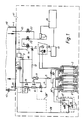
- FIGS. 1 and 2 show schematic basic representations (partly in vertical section) of a cooling container according to the invention
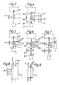
- FIGS. 3 to 7 show different schematic embodiments of heat exchanger arrangements
- FIGS. 8 and 9 show two embodiments of heat exchangers
- FIG. 10 shows a schematic sectional view from above.
- FIG. 1 schematically shows a cooling container 1, with a device space 41 and a cooling space 40, into which nitrogen is fed via a line 4 from containers 2, in which liquid nitrogen is contained.
- the liquid nitrogen is filled into the container 2 at the start of the storage via a filling valve 19 and corresponding lines 19 ', which contain, among other things, a non-return valve 30'.
- a ventilation valve is designated and with 17 a three-way solenoid valve, which is preceded by an overpressure safety valve 17 '.
- Fig. 10 shows schematically that the refrigerator compartment 40 is connected or attached to the equipment compartment 41.
- the three containers 2 for N2 and a container 2 'for CO2 are arranged.
- the cooling unit 3 including sensors is arranged separately in a department, via which the cooling chamber atmosphere is circulated.
- the control unit, the condenser of the cooling unit and further structural units are arranged in one or more further compartments (km). 1 schematically indicates how the return air is conducted via the cooling unit 3 and fed into the cooling space 40 as cooled supply air.
- the maintenance of the pressure of the composition and the temperature of the atmosphere in the cooling space 40 is regulated by a computer 13, which interrogates measuring instruments 20 or a sensor box 16 and controls all valves, control and setting devices for the container parameters or to all sensors, for example gas -, Pressure and temperature sensors inside the container, is connected. Furthermore, the computer monitors the outside temperature, the idle times, etc. and is thus set up to control the entire cooling process on its own by giving access to all control units owns.
- the nitrogen required for calibration of the sensor box 16 or the measuring devices is drawn off from the containers 2 via a line 12 which has a heat exchanger 11 in which the nitrogen is heated by thermal contact with the ambient air.
- the nitrogen flows in line 12 via a throttle 23 to a three-way valve 21, which connects line 12 or line 14, via which ambient air can be drawn in, via a shut-off valve 22 to sensor box 16, which in turn has a further shut-off valve 22 via a Line 15 can be connected to the atmosphere in the cold room 40 so that it can carry out comparative measurements using nitrogen / outside air and cold room atmosphere.
- line 12 or the pressure prevailing therein serves to control the pressure of a pneumatic valve 9 via line 10, which pneumatic valve 9 can open, close and regulate a low-temperature valve 8 located in line 4.
- the line 4 is led in Figure 1 via a heat exchanger 5 for heat exchange with the ambient air and a heat exchanger 7 ', which is located in the circuit 32 of the refrigerant of the cooling unit 3. With 32 the refrigerant lines are indicated, which are compressed by the compressor of the refrigeration device 3, i.e. warm coolant included.
- the line 4 opens into the cooling space 40 of the container via a nozzle 29. It would also be possible to have the nozzle or a throttle or a comparable device outside the cooling space in the line 4, possibly also in front of the heat exchangers 6 and 7 ', to arrange.
- the line 28 is led into the cooling space 40 of the container 1, with which the nitrogen continuously evaporating in the containers 2 is regulated under Control unit 13 can be introduced into the storage room 40. If an N2 introduction into the refrigerator is not necessary, the N2 is released to the environment via 17 ''.
- the line 28 could, as indicated by dashed lines at 29 ', be routed via the heat exchanger 6 or the heat exchanger 7' in order to give the nitrogen passed through a higher temperature. With 43 a pressure relief valve for the cooling room 1 is designated.
- FIG. 2 shows schematically a container 1 which is in the cooling space 40, which is optionally also provided with a heater 42 (for example for rapid heating of the goods), and in a device space 41 in which (see also FIG. 10) the cooling unit 3, the nitrogen tank 2, the CO2 container 2; the control device 13 and the other technical devices are divided.
- the line 28 for the nitrogen which naturally evaporates in the containers 2 is led into the cooling space 40 and / or equipment room 41 via the valves 17, 17 '.
- CO2 is introduced into the equipment room 41 and / or the cooling room 40, the introduction can take place before or after the evaporator 39 or in the supply air and / or return air flow.
- the heat exchanger 6, the heat exchanger 7 'and via the throttle or nozzle 29, nitrogen is fed into the cooling chamber 40 at a temperature which essentially corresponds to the temperature.
- the container atmosphere is circulated via the evaporator 39 of the cooling unit 3 by means of an evaporator fan 44 and conveyed into the cooling space 40 via indicated channels 45 or drawn off from it.
- the atmosphere is circulated via the evaporator 39 of the cooling unit 3 from top to bottom or essentially vertically.
- an evaporation pressure regulator 36 is arranged, to which a bypass valve 37 is connected in parallel.
- a compressor 31 is arranged in the flow path, from which heated, compressed coolant reaches the heat exchanger 7 ', to which a bypass 33 is connected in parallel.
- the line 32 passes through a check valve 34 and the heat exchanger 7, which is in thermal contact with the condenser 25 of the cooling unit and which is supplied with ambient air by a condenser fan 25 '.
- the coolant is fed to the evaporator 39 via an expansion valve 30 via a dryer 35 and a preheater 38 and is carried on in the circuit.
- bypass line 33 ' for the heat exchanger 7' is necessary because when the compressor 31 is stopped, the nitrogen fed via the line 4 into the cooling space 40 could cause the refrigerant in the line 32 to solidify or become blocked and when the Work of the compressor 31, the line 32 or other components can be damaged due to the excess pressure. Accordingly, the pressure relief valve 33 is arranged in the bypass 33 'and opens at a certain pressure in the line 32. As soon as the compressor starts to work, the refrigerant compressed by the compressor heats the solidified refrigerant in the heat exchanger 7 ', whereupon the flow through the heat exchanger 7 is released again, whereupon the bypass valve 33 closes and the entire amount of refrigerant flows through the heat exchanger 7'. Corresponding it is provided that the bypass line 33 'is passed close enough to the heat exchanger 7' so that on the one hand this line cannot freeze and on the other hand the heat exchanger 7 'can be thawed by this line.
- FIG. 3 schematically shows a device for heating the nitrogen, in which nitrogen is passed from the nitrogen container 2 into the cooling space of the refrigerated container 1.
- the line 4 is passed through a heat exchanger 6 for thermal contact with the ambient air, which can be acted upon by a fan 24.
- FIG 4 shows a device with a heat exchanger 7 ', in which a heat exchange takes place between the refrigerant led from the refrigeration unit 3 or from the compressor 31 via the line 32 to the condenser 25 and the nitrogen conducted in the line 4.
- a bypass line 33 'with a bypass valve 33 is assigned to the heat exchanger 7'.
- FIG. 5 shows a device in which a heat exchanger 7 is arranged in the nitrogen line 4, which is combined with the condenser 25 of the refrigeration unit 3 to form a structural unit and with which a blower, in particular the condenser blower 25 ′′, is supplied with ambient air.
- FIG. 6 shows a device in which a heat exchanger for outside air contact 6 is arranged in the nitrogen line 4, which is optionally supplied with outside air by a blower 24. Furthermore, a heat exchanger 7 ′ is arranged in the line 4, which is located in the refrigerant circuit between the compressor 31 and the condenser 25 and is optionally supplied with ambient air by a blower 24 in order to heat the nitrogen in the line 4.
- FIG. 7 shows an arrangement in which a heat exchanger 6 acted upon by a blower 24 is arranged in the line 4 for heat exchange with outside air and in which a structural unit 7 comprising a heat exchanger and the condenser 25 is arranged, which is driven by a blower 25 '. , in particular the condenser fan.
- FIG. 8 shows an arrangement in which heat exchangers, in particular in the form of finned tubes or grates or plates, are combined to form an arrangement 7 'through which air flows through a fan 25'.
- heat exchangers in particular in the form of finned tubes or grates or plates
- FIG. 9 an arrangement could also be provided in which the refrigerant line 32 is passed through a container through which nitrogen from the nitrogen line 4 flows.
- Heat exchangers for thermal contact with the outside air like the heat exchangers for exchanging heat with the refrigerant circulated in line 32, can have any shape.
- the shape or structure of the structural unit which represents a combination of the heat exchanger for the nitrogen with the condenser 25 of the refrigerant unit 3, is left to the person skilled in the art.
- Such heat exchangers will of course be designed according to the aspects of the best possible heat exchange.
- the cooling energy of the nitrogen carried is not used for cooling, but liquid nitrogen is used in order to be able to carry as large a quantity of nitrogen as possible.
- the nitrogen temperature or heating the nitrogen By regulating the nitrogen temperature or heating the nitrogen to a value which is a little less than the temperature in the cooling space 40, the cooling effect of the nitrogen or its cooling energy is exploited to a certain extent without impairing the goods stored in the cooling space 40.
- the throughput the nitrogen or the refrigerant through the heat exchangers and / or the power of the blowers 24, 25 ', the power of the cooling unit, the opening and closing of the feed valves, etc. is carried out under the control of the control unit 13.
- the valve or throttle 29, which inhibits or controls the flow of nitrogen can be used to regulate the temperature of the nitrogen fed in by crossing the heat exchanger more quickly or more slowly.
- the throttle 29 regulates the nitrogen pressure in the line 4 or the consumption and is controlled by the computer 13.
- the blowers 24 and 25 ' are advantageously run in such a way that in the case of combined units of heat exchanger and condenser or heat exchanger and refrigerant line 32, the refrigerant 32 is prevented from stalling or becoming solid.
- the line 28 can be routed via external heat exchangers or heat exchangers assigned to the condenser 25 or arranged in the refrigerant line 32.
- the container When filling the container for the first time, the container is pre-cooled with a normal atmosphere, then the goods are put into storage, and then nitrogen is gassed or the container atmosphere is set and cooled, which takes about 6 hours.
- the computer 13 and the sensor box 16 measure, inter alia, the content of nitrogen, CO2, argon, ethylene, etc. in the cold room.
- the room humidity R T etc. are referred to, which can be located in the cooling chamber 40 or in the equipment room 41 in the flow path, in particular upstream from the evaporator or from the evaporator fan 44 or advantageously before the outlet of the return air.
- the setting of the composition of the atmosphere of the cooling container according to the invention is preferably carried out in such a way that the N2 content of the atmosphere is regulated with the entrained N2, excess oxygen preferably being flushed out with N2.
- the CO2 content is preferably adjusted with the aid of a CO2 scrubber or molecular sieve 48 or by supplying CO2 from the container 2 'carried along.
- a too low O2 content is compensated for by supplying outside air with a supply device 47, a pump.
- Other atmospheric constituents to be regulated (ethylene, argon) can be regulated by flushing with N2 or by supplying them from their own containers. All setting and control processes are carried out by the control device.
- control unit for the possible regulation of the heating devices for the nitrogen.
- a valve opening at a predetermined pressure in the refrigerant line is provided in the bypass line.
- control unit controls the air supply to the heat exchangers e.g. by means of adjustable air blinds, speed control devices for the blowers or the like. With the control unit, the extent of the heating of the N2 can be adapted to the cooling parameters or the cooling conditions and the amount and / or the pressure of the N2 to be fed in can be adjusted.
Landscapes
- Engineering & Computer Science (AREA)
- Chemical & Material Sciences (AREA)
- General Engineering & Computer Science (AREA)
- Physics & Mathematics (AREA)
- Mechanical Engineering (AREA)
- Thermal Sciences (AREA)
- Combustion & Propulsion (AREA)
- Life Sciences & Earth Sciences (AREA)
- Wood Science & Technology (AREA)
- Zoology (AREA)
- Food Science & Technology (AREA)
- Polymers & Plastics (AREA)
- Devices That Are Associated With Refrigeration Equipment (AREA)
Abstract
Claims (23)
- Récipient frigorifique, en particulier container frigorifique pour le transport ou le stockage de marchandises à l'intérieur duquel on introduit de l'azote pour le maintien de la composition de l'atmosphère en particulier, l'azote étant transporté sous forme liquide dans des récipients accompagnant le récipient frigorifique, où au moins un groupe frigorifique est prévu pour le refroidissement de l'atmosphère du récipient frigorifique (1), caractérisé en ce que l'atmosphère est mise en circulation en passant par le groupe frigorifique (3) à l'aide d'au moins un ventilateur (44) pendant des laps de temps déterminés par un dispositif de commande (13) et qu'au moins un dispositif (6, 7, 7') est prévu pour le réchauffement de l'azote avant son introduction dans la chambre frigorifique (40) du récipient frigorifique (1), ce dispositif permettant de réchauffer l'azote à une température qui correspond sensiblement à la température qui règne à l'intérieur de la chambre frigorifique (40) en étant de préférence très légèrement inférieure, en particulier jusqu'à 5 % inférieure à cette dernière.
- Récipient selon la revendication 1, caractérisé en ce que le dispositif de réchauffement de l'azote est constitué par au moins un échangeur de chaleur (6, 7, 7') situé à l'extérieur de la chambre frigorifique (40) et disposé dans la conduite d'azote (4) qui mène du récipient d'azote (2) vers la chambre frigorifique (40).
- Récipient selon la revendication 1 ou 2, caractérisé en ce que le dispositif de réchauffement de l'azote comporte au moins un échangeur de chaleur (6) disposé à l'extérieur de la chambre frigorifique (40) et qui est en contact thermique avec l'air ambiant ou, selon le cas, soumis à un courant d'air ambiant et/ou comporte au moins un échangeur de chaleur (7') qui est disposé dans la conduite de fluide frigorigène (32) entre le compresseur (31) et le condenseur (25) du groupe frigorifique (3) et/ou comporte un échangeur de chaleur (7) qui est situé dans la conduite de fluide frigorigène (32) et est en contact thermique avec le condenseur (25).
- Récipient selon l'une quelconque des revendications 1 à 3, caractérisé en ce que l'échangeur de chaleur (6) destiné à l'échange thermique avec l'air ambiant est monté en amont de l'échangeur de chaleur (7, 7') destiné à l'échange thermique avec le fluide frigorigène dans la conduite de fluide frigorigène (32).
- Récipient selon l'une quelconque des revendications 1 à 4, caractérisé en ce que le tronçon de conduite de fluide frigorigène (32) qui est en contact d'échange thermique avec la conduite (4) destiné à l'azote, ou, selon le cas, l'échangeur de chaleur (7') traversé par le fluide frigorigène et l'azote à réchauffer est ponté par une conduite de dérivation (33').
- Récipient selon la revendication 5, caractérisé en ce que dans la conduite de dérivation (33') est prévue une soupape (33) qui s'ouvre lorsque la pression dans la conduite de fluide frigorigène (32) atteint une valeur prédéterminée.
- Récipient selon l'une quelconque des revendications 1 à 6, caractérisé en ce que le dispositif (6, 7, 7') de réchauffement de l'azote comporte un ensemble échangeur, un tube à ailettes p.ex., traversé par l'azote et qui est en contact thermique ou, selon le cas, regroupé en un ensemble de construction avec un ensemble échangeur, un tube à ailettes p.ex., traversé par le fluide frigorigène entre le compresseur (31) et le condenseur (25) du groupe frigorifique (3).
- Récipient selon l'une quelconque des revendications 1 à 7, caractérisé en ce que le condenseur (25) destiné au fluide frigorigène est regroupé en un ensemble (7') avec un échangeur de chaleur dans la conduite d'azote (4).
- Récipient selon l'une quelconque des revendications 1 à 8, caractérisé en ce que les échangeurs de chaleur (6, 7, 7') ou, selon le cas, les ensembles en contact thermique sont alimentés en air ambiant ou, selon le cas, soumis à un courant d'air ambiant à l'aide de ventilateurs (24, 25') respectivement du ventilateur (25'') du condenseur.
- Récipient selon l'une quelconque des revendications 1 à 9, caractérisé en ce que dans la conduite d'introduction (4) de l'azote réchauffé à l'intérieur de la chambre frigorifique (40) est prévu au moins un dispositif d'étranglement (29), réglable le cas échéant, p.ex. une buse, une soupape réglable ou organe similaire, de préférence de la partie d'extrémité de la conduite (4) et/ou en amont des dispositifs (6, 7, 7') de réchauffement de l'azote.
- Récipient selon l'une quelconque des revendications 1 à 10, caractérisé en ce que le récipient d'azote (2) présente une conduite d'aération ou, selon le cas, une conduite de décharge (28) menant à l'intérieur de la chambre frigorifique (40).
- Récipient selon la revendication 11, caractérisé en ce que dans la conduite de décharge (28) qui renferme le cas échéant une soupape de sûreté (17') est disposé de préférence en aval de la soupape de sûreté (17') une distributeur trois voies (17) permettant l'ouverture de la conduite de décharge vers l'environnement ambiant.
- Récipient selon la revendication 11 ou 12, caractérisé en ce que dans la chambre frigorifique (40) est disposé une soupape de surpression (43) ajustable à une pression donnée.
- Récipient selon l'une quelconque des revendications 1 à 13, caractérisé en ce que dans la conduite (28) menant du récipient d'azote (2) dans la chambre frigorifique (40) est disposé au moins un dispositif de réchauffage de l'azote, ou que dans cette conduite (28) est disposé un échangeur de chaleur destiné au contact thermique avec l'air ambiant, et/ou que dans cette conduite (28) est disposé un échangeur de chaleur pour l'échange de chaleur avec le fluide frigorigène du groupe frigorifique (3) entre le compresseur (31) et le condenseur (25).
- Récipient selon l'une quelconque des revendications 1 à 14, caractérisé en ce que le ventilateur (44) pour la circulation de l'atmosphère effectuée à l'intérieur du récipient (1) est un ventilateur normalement à l'arrêt et capable d'être mis en marche par le dispositif de commande (13) selon des intervalles de temps qui sont déterminés arbitrairement ou en fonction de la valeur de certains paramètres à l'intérieur ou, selon le cas, à l'extérieur du récipient (1) tels que la température et/ou l'humidité (humidité relative), et pour une durée de marche prédéterminée ou dépendant de la valeur des paramètres.
- Récipient selon l'une quelconque des revendications 1 à 15, caractérisé en ce que le(s) dispositif(s) (6, 7, 7') de réchauffement de l'azote est (sont) commandé(s) par une unité de commande, le cas échéant par le dispositif de commande (13) en vue de régler la température et/ou le débit autorisé de l'azote à introduire qui doit être réchauffé.
- Récipient selon la revendication 16, caractérisé en ce que l'unité de commande commande des volets à persienne réglables pour le débit d'air du ventilateur, et/ou des dispositifs de réglage, étrangleurs, p.ex., pour l'azote N₂ à introduire.
- Récipient selon l'une quelconque des revendications 1 à 17, caractérisé en ce que le dispositif de commande règle l'alimentation d'air vers les échangeurs de chaleur (6, 7, 7') p.ex. au moyen de volets d'air à persienne, dispositifs de commande de la vitesse de rotation pour les ventilateurs (24, 25', 25'') ou moyens similaires.
- Récipient selon l'une quelconque des revendications 10 à 18, caractérisé en ce que le dispositif de commande règle le dispositif d'étranglement (29).
- Procédé de refroidissement pour récipients frigorifiques, en particulier containers frigorifiques pour le transport ou le stockage de marchandises à l'intérieur desquels on introduit de l'azote pour le maintien de la composition de l'atmosphère en particulier, l'azote étant transporté sous forme liquide dans des récipients accompagnant les récipients frigorifiques, ou l'atmosphère des récipients frigorifiques (1) est refroidi par au moins un groupe frigorifique, caractérisé en ce que l'atmosphère est mise en circulation pendant des laps de temps déterminés en vue de son refroidissement, et que l'azote est réchauffé avant son introduction dans la chambre frigorifique (40) du récipient frigorifique (1) à une température qui correspond sensiblement à la température qui règne à l'intérieur de la chambre frigorifique (40) en étant de préférence très légèrement inférieure, en particulier jusqu'à 5 % inférieure à cette dernière.
- Procédé selon la revendication 20, caractérisé en ce que l'azote est réchauffé pendant son trajet du récipient d'azote (2) vers la chambre frigorifique (40).
- Procédé selon la revendication 20 ou 21, caractérisé en ce que l'azote est réchauffé par contact thermique avec l'air ambiant et/ou moyennant l'air qui est alimenté à travers le compresseur (31) et/ou le condenseur (25) du groupe frigorifique (3).
- Procédé selon l'une quelconque des revendications 20 à 22, caractérisé en ce que l'on adapte la pression de l'azote introduite dans la chambre frigorifique (40) à la pression intérieure dans la chambre frigorifique (40).
Applications Claiming Priority (2)
| Application Number | Priority Date | Filing Date | Title |
|---|---|---|---|
| AT0196888A AT391756B (de) | 1988-08-04 | 1988-08-04 | Kuehlbehaelter |
| AT1968/88 | 1988-08-04 |
Publications (2)
| Publication Number | Publication Date |
|---|---|
| EP0429499A1 EP0429499A1 (fr) | 1991-06-05 |
| EP0429499B1 true EP0429499B1 (fr) | 1993-07-14 |
Family
ID=3524951
Family Applications (2)
| Application Number | Title | Priority Date | Filing Date |
|---|---|---|---|
| EP89909121A Expired - Lifetime EP0429499B1 (fr) | 1988-08-04 | 1989-08-04 | Procede et conteneur de refroidissement |
| EP89890207A Withdrawn EP0357587A1 (fr) | 1988-08-04 | 1989-08-04 | Procédé de refroidissement et conteneur frigorifique |
Family Applications After (1)
| Application Number | Title | Priority Date | Filing Date |
|---|---|---|---|
| EP89890207A Withdrawn EP0357587A1 (fr) | 1988-08-04 | 1989-08-04 | Procédé de refroidissement et conteneur frigorifique |
Country Status (7)
| Country | Link |
|---|---|
| US (1) | US5172558A (fr) |
| EP (2) | EP0429499B1 (fr) |
| KR (1) | KR930012238B1 (fr) |
| AT (1) | AT391756B (fr) |
| AU (1) | AU630368B2 (fr) |
| CA (1) | CA1330880C (fr) |
| WO (1) | WO1990001661A1 (fr) |
Families Citing this family (14)
| Publication number | Priority date | Publication date | Assignee | Title |
|---|---|---|---|---|
| US5308382A (en) * | 1993-04-16 | 1994-05-03 | Praxair Technology, Inc. | Container inerting |
| US5333394A (en) * | 1993-06-17 | 1994-08-02 | Chiquita Brands, Inc. | Controlled atmosphere container system for perishable products |
| US5658607A (en) * | 1993-07-08 | 1997-08-19 | Chiquita Brands, Inc. | Process for shipping and ripening fruits and vegetables |
| US5460841A (en) * | 1993-07-08 | 1995-10-24 | Chiquita Brands, Inc. | Process for ripening bananas and other produce |
| US5457963A (en) * | 1994-06-15 | 1995-10-17 | Carrier Corporation | Controlled atmosphere system for a refrigerated container |
| US5649995A (en) * | 1995-03-09 | 1997-07-22 | Nitec, Inc. | Nitrogen generation control systems and methods for controlling oxygen content in containers for perishable goods |
| GB2314891A (en) * | 1995-03-31 | 1998-01-14 | Spembly Cryosurgery Limited | Method and Apparatus for Supplying Liquid Cryogen |
| GB9506652D0 (en) * | 1995-03-31 | 1995-05-24 | Cryogenic Technology Ltd | Supplying liquid cryogen to cryosurgical apparatus |
| US5899084A (en) * | 1997-01-10 | 1999-05-04 | Chiquita Brands, Inc. | Method and apparatus for ripening perishable products in a temperature-controlled room |
| EP0906024B1 (fr) * | 1996-04-11 | 2003-07-30 | CHIQUITA BRANDS, Inc | Procede et appareil permettant de faire murir des denrees perissables dans une chambre a temperature reglable |
| US5974815A (en) * | 1998-02-03 | 1999-11-02 | Carrier Corporation | Humidity control system for cargo container |
| US6578367B1 (en) | 2001-03-02 | 2003-06-17 | Ta Instruments-Waters Llc | Liquid nitrogen cooling system |
| US20100126192A1 (en) * | 2008-11-25 | 2010-05-27 | Sanfanandre Al | Spot cooling system for open boats |
| CN116812108B (zh) * | 2023-08-28 | 2024-09-20 | 深圳艾迪宝智能系统有限公司 | 集装箱船舶气场矩阵节能的系统 |
Family Cites Families (20)
| Publication number | Priority date | Publication date | Assignee | Title |
|---|---|---|---|---|
| US3239360A (en) * | 1964-04-01 | 1966-03-08 | Best Fertilizers Co | Method for transporting produce under controlled atmosphere |
| US3360380A (en) * | 1964-04-20 | 1967-12-26 | Whirlpool Co | Method of storing banas |
| US3487769A (en) * | 1965-04-26 | 1970-01-06 | Occidental Petroleum Corp | Apparatus for controlled admission of air to controlled atmosphere |
| DE1517545A1 (de) * | 1966-11-30 | 1970-01-22 | Linde Ag | Verfahren und Vorrichtung zur Meerwasserentsalzung bei gleichzeitiger Verdampfung tiefsiedender Fluessigkeiten,insbesondere fluessigem Naturgas |
| US3421336A (en) * | 1967-06-05 | 1969-01-14 | Union Carbide Corp | Intransit liquefied gas refrigeration system |
| AU2773167A (en) * | 1967-09-26 | 1969-04-03 | TOM H. MURPHY and DONE. TUCKER | Combined liquid gas-mechanical freezing process and apparatus therefor |
| DE1601874A1 (de) * | 1968-01-12 | 1971-02-04 | Waggon Und Maschinenfabriken G | Kuehl-Container |
| CH499269A (fr) * | 1968-10-29 | 1970-11-30 | Batelle Memorial Inst Internat | Installation de conservation de produits périssables dans une chambre froide |
| US3705500A (en) * | 1969-10-22 | 1972-12-12 | Union Carbide Corp | Nitrogen spray refrigeration system for perishables |
| US3830078A (en) * | 1970-03-24 | 1974-08-20 | Us Air Force | Anti-frost apparatus |
| FR2330608A1 (fr) * | 1975-11-04 | 1977-06-03 | Sermaf | Conteneur refrigere autonome |
| US4315413A (en) * | 1979-12-31 | 1982-02-16 | Whirlpool Corporation | Selective temperature control system |
| US4454723A (en) * | 1981-09-28 | 1984-06-19 | Weasel George E Jr | Refrigerated produce transport |
| US4485633A (en) * | 1982-10-18 | 1984-12-04 | The Coca-Cola Company | Temperature-based control for energy management system |
| DE3310012A1 (de) * | 1983-03-19 | 1984-10-18 | Bergwerksverband Gmbh, 4300 Essen | Verfahren und vorrichtung zum inertisieren von transport-containern |
| DE3319249C1 (de) * | 1983-05-27 | 1984-10-11 | Messer Griesheim Gmbh, 6000 Frankfurt | Verfahren zum Erzeugen einer Inertgasatmosphaere konstanter Zusammensetzung aus Stickstoff und Kohlendioid in einem Kuehlcontainer |
| NZ205453A (en) * | 1983-09-01 | 1988-03-30 | New Zealand Shipping | Transporting respiring comestibles while monitoring and adjusting oxygen and carbon dioxide levels |
| AT384668B (de) * | 1985-11-28 | 1987-12-28 | Welz Franz Transporte | Transportabler kuehlcontainer |
| AT395933B (de) * | 1986-02-17 | 1993-04-26 | Welz Franz Transporte | Verfahren zur einstellung bzw. aufrechterhaltung einer gekuehlten atmosphaere in einem kuehlbehaelter und kuehlbehaelter zur durchfuehrung des verfahrens |
| US4727727A (en) * | 1987-02-20 | 1988-03-01 | Electric Power Research Institute, Inc. | Integrated heat pump system |
-
1988
- 1988-08-04 AT AT0196888A patent/AT391756B/de not_active IP Right Cessation
-
1989
- 1989-08-03 CA CA000607491A patent/CA1330880C/fr not_active Expired - Fee Related
- 1989-08-04 US US07/613,828 patent/US5172558A/en not_active Expired - Fee Related
- 1989-08-04 KR KR1019900700695A patent/KR930012238B1/ko not_active Expired - Fee Related
- 1989-08-04 EP EP89909121A patent/EP0429499B1/fr not_active Expired - Lifetime
- 1989-08-04 EP EP89890207A patent/EP0357587A1/fr not_active Withdrawn
- 1989-08-04 WO PCT/AT1989/000070 patent/WO1990001661A1/fr not_active Ceased
- 1989-08-04 AU AU40637/89A patent/AU630368B2/en not_active Ceased
Also Published As
| Publication number | Publication date |
|---|---|
| EP0357587A1 (fr) | 1990-03-07 |
| ATA196888A (de) | 1990-05-15 |
| US5172558A (en) | 1992-12-22 |
| EP0429499A1 (fr) | 1991-06-05 |
| AU4063789A (en) | 1990-03-05 |
| AT391756B (de) | 1990-11-26 |
| KR930012238B1 (ko) | 1993-12-24 |
| CA1330880C (fr) | 1994-07-26 |
| KR900702309A (ko) | 1990-12-06 |
| AU630368B2 (en) | 1992-10-29 |
| WO1990001661A1 (fr) | 1990-02-22 |
Similar Documents
| Publication | Publication Date | Title |
|---|---|---|
| EP0429499B1 (fr) | Procede et conteneur de refroidissement | |
| DE60124502T2 (de) | Flüssigen stickstoff verwendende kühlung eines lastfahrzeuges für nahrungsmittel | |
| EP0224469B2 (fr) | Conteneur frigorifique transportable | |
| DE69133520T2 (de) | Enthalpiesteuerung für ein CO2-Kältesystem | |
| DE69328407T2 (de) | Luftkonditionierungs- und Kühlsysteme mit Nutzung eines Kryogens und Wärmeleitungen | |
| DE69922039T2 (de) | Mobiler reifungsbehälter | |
| DE69526039T2 (de) | Verfahren und Vorrichtung zum Fördern und Lagern von gekühlten Waren | |
| DE68902452T2 (de) | Verfahren und anlage zur aufbewahrung von erzeugnissen. | |
| DE10229864A1 (de) | Tiefsttemperatur-Steuervorrichtung und -Verfahren | |
| DE69414847T2 (de) | Verfahren zum fruchten-oder gemuese versenden und reifen mit gebrauch von behaelternsystem mit kontrollierter atmosphaere fuer verderblichen waren | |
| DE69326869T2 (de) | Verfahren zur Steuerung der Temperatur eines klimatisierten Raumes unter Verwendung eines Kryogens | |
| DE102005045760A1 (de) | Verfahren und Vorrichtung zur Herstellung einer konditionierten Atmosphäre | |
| EP0126996B1 (fr) | Procédé pour produire dans un récipient frigorifique une atmosphère de gaz inerte d'une composition constante, comprenant de l'azote et du dioxyde de carbone | |
| DE3887690T2 (de) | Bewegliche gekühlte zelle für lebensmittel. | |
| DE1629857A1 (de) | Tiefkuehlung und Gasspeicherung | |
| DE2303869A1 (de) | Verfahren und vorrichtung zum spruehkuehlen von gegenueber niedrigen temperaturen empfindlichem gut | |
| DE935196C (de) | Verfahren zur Abgabe eines Gases | |
| EP1110043A1 (fr) | Procede et dispositif pour refroidir un contenant | |
| DE1958348A1 (de) | Verfahren und Vorrichtung zum Spruehkuehlen | |
| DE102008027244A1 (de) | Verfahren und Vorrichtung zur Kühlung des Innenraumes eines Kühltransporters | |
| DE3003987A1 (de) | Mit einer kuehleinrichtung versehener kleincontainer | |
| DE1601899A1 (de) | Luftfracht-Kuehlbehaelter | |
| DE2626000A1 (de) | Verfahren und anlage zur kuehlung von losen guetern | |
| DE1902497A1 (de) | Anlage zur Energieerzeugung in einem Gaskreislauf | |
| DE4120334C2 (de) | Controlled-Atmosphere-System |
Legal Events
| Date | Code | Title | Description |
|---|---|---|---|
| PUAI | Public reference made under article 153(3) epc to a published international application that has entered the european phase |
Free format text: ORIGINAL CODE: 0009012 |
|
| 17P | Request for examination filed |
Effective date: 19910131 |
|
| AK | Designated contracting states |
Kind code of ref document: A1 Designated state(s): DE FR GB IT NL |
|
| 17Q | First examination report despatched |
Effective date: 19920422 |
|
| GRAA | (expected) grant |
Free format text: ORIGINAL CODE: 0009210 |
|
| AK | Designated contracting states |
Kind code of ref document: B1 Designated state(s): DE FR GB IT NL |
|
| PG25 | Lapsed in a contracting state [announced via postgrant information from national office to epo] |
Ref country code: IT Free format text: LAPSE BECAUSE OF FAILURE TO SUBMIT A TRANSLATION OF THE DESCRIPTION OR TO PAY THE FEE WITHIN THE PRE;WARNING: LAPSES OF ITALIAN PATENTS WITH EFFECTIVE DATE BEFORE 2007 MAY HAVE OCCURRED AT ANY TIME BEFORE 2007. THE CORRECT EFFECTIVE DATE MAY BE DIFFERENT FROM THE ONE RECORDED.SCRIBED TIME-LIMIT Effective date: 19930714 Ref country code: NL Effective date: 19930714 Ref country code: FR Effective date: 19930714 Ref country code: GB Effective date: 19930714 |
|
| REF | Corresponds to: |
Ref document number: 58904921 Country of ref document: DE Date of ref document: 19930819 |
|
| EN | Fr: translation not filed | ||
| NLV1 | Nl: lapsed or annulled due to failure to fulfill the requirements of art. 29p and 29m of the patents act | ||
| GBV | Gb: ep patent (uk) treated as always having been void in accordance with gb section 77(7)/1977 [no translation filed] |
Effective date: 19930714 |
|
| PLBE | No opposition filed within time limit |
Free format text: ORIGINAL CODE: 0009261 |
|
| STAA | Information on the status of an ep patent application or granted ep patent |
Free format text: STATUS: NO OPPOSITION FILED WITHIN TIME LIMIT |
|
| 26N | No opposition filed | ||
| PGFP | Annual fee paid to national office [announced via postgrant information from national office to epo] |
Ref country code: DE Payment date: 19941223 Year of fee payment: 6 |
|
| PG25 | Lapsed in a contracting state [announced via postgrant information from national office to epo] |
Ref country code: DE Effective date: 19960501 |