EP0429514B1 - Optoelektronische messanordnung - Google Patents
Optoelektronische messanordnung Download PDFInfo
- Publication number
- EP0429514B1 EP0429514B1 EP89909548A EP89909548A EP0429514B1 EP 0429514 B1 EP0429514 B1 EP 0429514B1 EP 89909548 A EP89909548 A EP 89909548A EP 89909548 A EP89909548 A EP 89909548A EP 0429514 B1 EP0429514 B1 EP 0429514B1
- Authority
- EP
- European Patent Office
- Prior art keywords
- light
- measuring arrangement
- receiver
- arrangement according
- bodies
- Prior art date
- Legal status (The legal status is an assumption and is not a legal conclusion. Google has not performed a legal analysis and makes no representation as to the accuracy of the status listed.)
- Expired - Lifetime
Links
- 230000005693 optoelectronics Effects 0.000 title claims abstract description 7
- 238000005259 measurement Methods 0.000 title abstract description 9
- 239000013598 vector Substances 0.000 claims abstract description 3
- 238000013519 translation Methods 0.000 claims description 4
- 230000000694 effects Effects 0.000 claims description 2
- 239000011159 matrix material Substances 0.000 claims description 2
- 230000011664 signaling Effects 0.000 claims 1
- 230000002123 temporal effect Effects 0.000 claims 1
- 125000004122 cyclic group Chemical group 0.000 abstract 1
- 238000011156 evaluation Methods 0.000 description 2
- 244000273618 Sphenoclea zeylanica Species 0.000 description 1
- 230000008878 coupling Effects 0.000 description 1
- 238000010168 coupling process Methods 0.000 description 1
- 238000005859 coupling reaction Methods 0.000 description 1
- 230000001419 dependent effect Effects 0.000 description 1
- 238000011161 development Methods 0.000 description 1
- 230000018109 developmental process Effects 0.000 description 1
- 238000010586 diagram Methods 0.000 description 1
- 239000000428 dust Substances 0.000 description 1
- 238000005516 engineering process Methods 0.000 description 1
- 230000001771 impaired effect Effects 0.000 description 1
- 238000000034 method Methods 0.000 description 1
Images

Classifications
-
- G—PHYSICS
- G01—MEASURING; TESTING
- G01D—MEASURING NOT SPECIALLY ADAPTED FOR A SPECIFIC VARIABLE; ARRANGEMENTS FOR MEASURING TWO OR MORE VARIABLES NOT COVERED IN A SINGLE OTHER SUBCLASS; TARIFF METERING APPARATUS; MEASURING OR TESTING NOT OTHERWISE PROVIDED FOR
- G01D5/00—Mechanical means for transferring the output of a sensing member; Means for converting the output of a sensing member to another variable where the form or nature of the sensing member does not constrain the means for converting; Transducers not specially adapted for a specific variable
- G01D5/26—Mechanical means for transferring the output of a sensing member; Means for converting the output of a sensing member to another variable where the form or nature of the sensing member does not constrain the means for converting; Transducers not specially adapted for a specific variable characterised by optical transfer means, i.e. using infrared, visible, or ultraviolet light
-
- G—PHYSICS
- G05—CONTROLLING; REGULATING
- G05G—CONTROL DEVICES OR SYSTEMS INSOFAR AS CHARACTERISED BY MECHANICAL FEATURES ONLY
- G05G9/00—Manually-actuated control mechanisms provided with one single controlling member co-operating with two or more controlled members, e.g. selectively, simultaneously
- G05G9/02—Manually-actuated control mechanisms provided with one single controlling member co-operating with two or more controlled members, e.g. selectively, simultaneously the controlling member being movable in different independent ways, movement in each individual way actuating one controlled member only
- G05G9/04—Manually-actuated control mechanisms provided with one single controlling member co-operating with two or more controlled members, e.g. selectively, simultaneously the controlling member being movable in different independent ways, movement in each individual way actuating one controlled member only in which movement in two or more ways can occur simultaneously
- G05G9/047—Manually-actuated control mechanisms provided with one single controlling member co-operating with two or more controlled members, e.g. selectively, simultaneously the controlling member being movable in different independent ways, movement in each individual way actuating one controlled member only in which movement in two or more ways can occur simultaneously the controlling member being movable by hand about orthogonal axes, e.g. joysticks
- G05G2009/0474—Manually-actuated control mechanisms provided with one single controlling member co-operating with two or more controlled members, e.g. selectively, simultaneously the controlling member being movable in different independent ways, movement in each individual way actuating one controlled member only in which movement in two or more ways can occur simultaneously the controlling member being movable by hand about orthogonal axes, e.g. joysticks characterised by means converting mechanical movement into electric signals
- G05G2009/04759—Light-sensitive detector, e.g. photoelectric
Definitions
- the invention relates to an optoelectronic measuring arrangement for determining the relative position of two bodies to one another.
- an optoelectronic measuring arrangement for determining the relative position of two bodies relative to one another is known, with light transmitters on the first body from which light rays emanate and position-sensitive, two-dimensionally measuring light receivers on the second body, on which the light rays strike, from the position of the impingement points and the beam axes are generated by the light receivers, the mutual translation and / or rotation signal pairs from which the relative position of the two bodies can be derived from each other.
- this measuring arrangement has the disadvantage that it requires three two-dimensional light receivers. Since the two-dimensionally measuring light receivers are expensive components, the economy of the entire measuring arrangement is hereby greatly impaired.
- the document FR-A-2 194 949 (Selcom) describes how the images of a plurality of point-shaped light sources can be distinguished by a different modulation of the individual light sources on a surface diode.
- the modulated light sources all of which aim to observe the chronological sequence of movement processes, such as a golf course, a jump or the start of a 100-meter run.
- At no point in the document is there any reference to find that the modulated light-emitting light points, together with the receiver, are intended to measure the relative position of two bodies.
- the invention is therefore based on the object of providing an optoelectronic measuring arrangement which enables the mutual position of two bodies in their six degrees of freedom with the smallest possible number of light receivers.
- an optoelectronic measuring arrangement 1 is shown schematically.
- the measuring arrangement 1 consists of, for example, three light transmitters 11, 12, 13 arranged on the first body, from which light rays 21, 22, 23 emanate and a position-sensitive, two-dimensionally measuring light receiver 3 on the second body.
- the light beams 21, 22, 23 are concentrated on the light receiver 3, for example by optics 24, 25, 26.
- the light transmitters 11, 12, 13 arranged on the first body form the corner points of a first triangle.
- the axes of the light beams 21, 22, 23 represent pairs of different direction vectors and each intersect the light receiver 3 at different angles, for example the three angles ⁇ 1, ⁇ 2, ⁇ 3. For drawing reasons, it is not possible to draw the angle ⁇ 2 in FIG. 1.
- the points of incidence 31, 32, 33 of the light beams 21, 22, 23 form a second triangle on the light receiver 3. By using more than three light sources, polygons are available instead of the two triangles.
- the measurement is now carried out in such a way that the light transmitters 11, 12, 13 emit light beam pulses that modulate on-off in a rotating sequence and do not overlap in length.
- the respective coordinates x, y of the three points of impact 31, 32, 33 can be determined one after the other.
- the ratio of a zero or reference measurement to a current measurement clearly shows the relative change in position of the two bodies relative to one another. If more than three light transmitters are used, then the measurements described above can be carried out with three of these light transmitters each, and the results compared and checked with one another.
- lasers, laser diodes, LE diodes or other light sources can be used, the light of which through light guides, optics or the like. is directed.
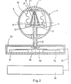
- a control handle 4 of a multidimensional joystick is shown in FIG. 2 as a first application example.
- the control handle 4 consists of the base body 5 and the handle (handle) 6.
- the base body 5 is mounted on a base 52 via a handle 51.
- On the top of the base body 5 are the three light transmitters 11, 12, 13, which throw their light rays 21, 22, 23 onto the light receiver 3.
- the line 92 leads from the transmitter electronics 91 to the Light transmitters 11, 12, 13 and the line 93 from the light receiver 3 to the receiving electronics 94.
- the light transmitters 11, 12, 13 and the light receiver 3 are encased by an elastic element, preferably a bellows 61. A mutual zero position is simultaneously fixed by the bellows 61. Oer bellows 61 also forms a dust and waterproof cover.
- the light receiver 3 can be a quadrant, matrix or lateral effect diode or a CCD receiver.
- the control handle 4 described above allows control with six degrees of freedom, since the handle 6 is spatially movable relative to the base body 5 and thus has three degrees of freedom for translation and three degrees of freedom for rotation. These six dimensions can be used to control a handling device with six or fewer degrees of freedom. However, if only the degrees of freedom in one plane are used, namely two degrees of freedom for the translation and one degree of freedom for the rotation, then a cursor can be shifted on this screen or an arrow similar to a cursor can be shifted and / or rotated. Its possible uses go beyond that of a "mouse" with which a cursor can only be moved on the screen.
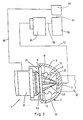
- FIG. 3 A simplified illustration of a handling device 7 is shown in FIG. 3 as a second application example.
- a stationary handle 6 is provided, which is mounted in a stationary manner with a fastening carrier 62.
- the handle 6 consists of an approximately hemispherical shell in which the light receiver 3 is mounted.
- the circular base body 5 carries the light transmitters 11, 12, 13, the light beams 21, 22, 23 on the Throw light receiver 3.
- the base body 5 is elastically supported on the handle 6 by the bellows 61.
- a flange 53 is attached to the base body 5.
- the control of the light transmitters 11, 12, 13 shown in FIG. 2 is carried out by transmitter electronics 91, which is connected to the light transmitters 11, 12, 13 by a line 92 and modulates this on-off.
- the reception signals of the light receiver 3 are passed through the reception line 93 to a reception electronics 94, which is connected via a line 95 to a computer interface with an evaluation computer 96.
- a line 97 between the computer and the control unit then routes the calculated values to a control unit 98, which in turn controls the handling device 7 via line 99.
Landscapes
- Physics & Mathematics (AREA)
- General Physics & Mathematics (AREA)
- Length Measuring Devices By Optical Means (AREA)
- Position Input By Displaying (AREA)
Abstract
Description
- Die Erfindung betrifft eine optoelektronische Meßanordnung zur Ermittlung der relativen Lage zweier Körper zueinander.
- Aus der DE-PS 33 14 089 ist eine optoelektronische Meßanordnung zur Ermittlung der relativen Lage zweier Körper zueinander bekannt, mit Lichtsendern am ersten Körper, von denen Lichtstrahlen ausgehen und positionsempfindliche, zweidimensional messende Lichtempfänger am zweiten Körper, auf die die Lichtstrahlen auftreffen, wobei aus der Lage der Auftreffpunkte und der Strahlenachsen von den Lichtempfängern die gegenseitige Translation und/oder Rotation darstellende Signalpaare erzeugt werden, aus denen die relative Lage beider Körper zueinander herleitbar ist. Dieser Meßanordnung haftet jedoch der Nachteil an, daß sie drei zweidimensional messende Lichtempfänger benötigt. Da die zweidimensional messenden Lichtempfänger teuere Bauteile sind, wird hierdurch die gesamte Meßanordnung in ihrer Wirtschaftlichkeit stark beeinträchtigt.
- In der Druckschrift FR-A-2 194 949 (Selcom) wird beschrieben, wie die Abbildungen mehrerer punktförmiger Lichtquellen durch eine unterschiedliche Modulation der einzelnen Lichtquellen auf einer Flächendiode unterscheidbar sind. Als Beispiele zur Anwendung der modulierten Lichtquellen werden jedoch nur Beispiele angeführt, die alle die Beobachtung des zeitlichen Ablaufes von Bewegungsvorgängen zum Ziel haben, wie z.B. eine Golfbahn, ein Sprung oder der Beginn eines 100-Meter Laufes. An keiner Stelle der Druckschrift ist jedoch ein Hinweis darauf zu finden, daß die moduliertes Licht emittierenden Lichtpunkte zusammen mit dem Empfänger zur meßtechnischen Erfassung der relativen Lage zweier Körper dienen sollen.
- In der Druckschrift GB-A-2 005 950 (HAY) werden Teilberechnungen für die gegenseitige Lage zweier Systeme durchgeführt. Mit einer Kamera und weiteren Anordnungen werden Hilfsberechnungen durchgeführt, damit z.B. eine Tunnelbohrmaschine ihren geraden Kurs einhält. Die Meßtechnik über ein Weitwinkelobjektiv einer Kamera stellt eine unpräzise Messung dar. Eine Berechnung der gegenseitigen Lage von zwei Systemen in sechs Freiheitsgraden wird nicht beschrieben. Die Punkte in den Zielebenen werden mit LEDs definiert, die in Folge durch Schalter betrieben werden.
- Der Erfindung liegt daher die Aufgabe zugrunde, eine optoelektronische Meßanordnung zu schaffen, die die gegenseitige Lage zweier Körper in ihren sechs Freiheitsgraden mit einer möglichst geringen Anzahl an Lichtempfängern ermöglicht.
- Diese Aufgabe wird nach der Erfindung wie im Patentanspruch 1 angegeben gelöst. In den abhängigen Patentansprüchen 2 bis 7 sind Fortbildungen der Erfindung beschrieben.
- In den Zeichnungen sind Ausführungsbeispiele der Erfindung wiedergegeben. Es zeigen :
- Fig. 1 eine Prinzipdarstellung von Lichtsendern und Lichtempfänger,
- Fig. 2 einen senkrechten Schnitt durch einen Joystick und
- Fig. 3 einen teilweisen Schnitt durch ein Handhabungsgerät.
- In Figur 1 ist eine optoelektronische Meßanordnung 1 schematisch wiedergegeben. Die Meßanordnung 1 besteht aus den am ersten Körper angeordneten, beispielsweise drei Lichtsendern 11, 12, 13, von denen Lichtstrahlen 21, 22, 23 ausgehen und einem positionsempfindlichen, zweidimensional messenden Lichtempfänger 3 am zweiten Körper. Die Lichtstrahlen 21, 22, 23 werden beispielsweise durch Optiken 24, 25, 26 auf den Lichtempfänger 3 konzentriert. Die am ersten Körper angeordneten Lichtsender 11, 12, 13 bilden die Eckpunkte eines ersten Dreiecks.
- Die Achsen der Lichtstrahlen 21, 22, 23 stellen paarweise verschiedene Richtungsvektoren dar und schneiden jeweils mit unterschiedlichen Winkeln, beispielsweise den drei Winkeln α1, α2, α3 den Lichtempfänger 3. Aus zeichnerischen Gründen ist es in Figur 1 nicht möglich, den Winkel α2 einzuzeichnen. Die Auftreffpunkte 31, 32, 33 der Lichtstrahlen 21, 22, 23 bilden auf dem Lichtempfänger 3 ein zweites Dreieck. Durch die Verwendung von mehr als drei Lichtquellen sind anstelle der beiden Dreiecke jeweils Vielecke vorhanden.
- Mit der vorbeschriebenen prinzipiellen Meßanordnung wird die Messung nun in der Weise durchgeführt, daß die Lichtsender 11, 12, 13 in umlaufender Folge Ein-Aus modulierte, sich in ihrer zeitlichen Länge nicht überschneidende Lichtstrahlimpulse aussenden. Hierdurch können die jeweiligen Koordinaten x, y der drei Auftreffpunkte 31, 32, 33 einzeln nacheinander ermittelt werden. Aus dem Verhältnis einer Null- oder Referenzmessung zu einer aktuellen Messung ergibt sich eindeutig die relative Lageveränderung beider Körper zu,einander. Werden mehr als drei Lichtsender verwandt, dann können mit jeweils drei dieser Lichtsender die vorbeschriebenen Messungen durchgeführt und die Ergebnisse untereinander verglichen und überprüft werden. Ergibt sich hierbei, daß ein Wert von den übrigen Ergebnissen signifikant abweicht was beispielsweise dann der Fall sein kann, wenn zwei Lichtpunkte eines Lichtpunktdreieckes 31, 32, 33 zu dicht nebeneinander liegen oder alle drei Lichtpunkte 31, 32, 33 auf einer Geraden liegen, so wird dieser Wert ausgeschieden. Hierdurch kann die Sicherheit und die Genauigkeit der Messung beträchtlich gesteigert werden.
- Zur Erzeugung der Lichtstrahlen 21, 22, 23 können vorzugsweise Laser, Laserdioden, LE-Dioden oder andere Lichtquellen verwendet werden, deren Licht durch Lichtleiter, Optiken od.dgl. geleitet wird.
- Als ein erstes Anwendungsbeispiel ist in Figur 2 ein Steuergriff 4 eines mehrdimensionalen Joysticks wiedergegeben. Der Steuergriff 4 besteht aus dem Grundkörper 5 und dem Griffstück (Handgriff) 6. Der Grundkörper 5 ist über einen Stiel 51 an einem Sockel 52 gelagert. Auf der Oberseite des Grundkörpers 5 befinden sich die drei Lichtsender 11, 12, 13, die ihre Lichtstrahlen 21, 22, 23 auf den Lichtempfänger 3 werfen. Durch den hohlen Stiel 51 führt die Leitung 92 von der Sendeelektronik 91 zu den Lichtsendern 11, 12, 13 und die Leitung 93 von dem Lichtempfänger 3 zur Empfangselektronik 94. Die Lichtsender 11, 12, 13 und der Lichtempfänger 3 sind von einem elastischen Element, vorzugsweise einem Federbalg 61 umhüllt. Durch den Federbalg 61 wird gleichzeitig eine gegenseitige Nullage fixiert. Oer Federbalg 61 bildet gleichzeitig auch eine staub- und wasserdichte Umhüllung.
- Der Lichtempfänger 3 kann eine Quadranten-, Matrix- oder Lateraleffektdiode oder ein CCD-Empfänger sein.
- Der vorstehend beschriebene Steuergriff 4 läßt eine Steuerung mit sechs Freiheitsgraden zu, da das Griffstück 6 gegenüber dem Grundkörper 5 räumlich bewegbar ist und somit drei Freiheitsgrade für Translation und drei Freiheitsgrade für Rotation hat. Diese sechs Dimensionen sind zur Steuerung eines Handhabungsgerätes mit sechs oder weniger Freiheitsgraden verwendbar. Werden jedoch nur die Freiheitsgrade in einer Ebene benutzt, nämlich zwei Freiheitsgrade für die Translation und ein Freiheitsgrad für die Rotation, dann kann hiermit auf einem Bildschirm ein Cursor verschoben oder ein cursorähnlicher Pfeil verschoben und/oder verdreht werden. Seine Einsatzmöglichkeiten gehen damit über die einer "Maus" hinaus, mit der ein Cursor lediglich auf dem Bildschirm verschiebbar ist.
- In Figur 3 ist als zweites Anwendungsbeispiel eine vereinfachte Darstellung eines Handhabungsgerätes 7 wiedergegeben. Hierbei ist ein ortsfestes Griffstück 6 vorhanden, das mit einem Befestigungsträger 62 ortsfest gelagert ist. Das Griffstück 6 besteht aus einer etwa halbkugeligen Schale, in der der Lichtempfänger 3 gelagert ist. Der kreisförmige Grundkörper 5 trägt die Lichtsender 11, 12, 13, die Lichtstrahlen 21, 22, 23 auf den Lichtempfänger 3 werfen. Der Grundkörper 5 ist durch den Federbalg 61 elastisch am Griffstück 6 gelagert. Am Grundkörper 5 ist ein Flansch 53 befestigt. An einem Ausleger des Handhabungsgerätes 7 befinden sich die Kupplung 71 mit Greifern 72, die bei einer Ankopplung den Flansch 53 umfassen und damit das System in Meßstellung bringen.
- Die in Figur 2 wiedergegebene Steuerung der Lichtsender 11, 12, 13 erfolgt durch eine Sendeelektronik 91, die durch eine Leitung 92 mit den Lichtsendern 11, 12, 13 verbunden ist und diese Ein-Aus moduliert. Entsprechend Figur 2 und Figur 3 werden die Empfangssignale des Lichtempfängers 3 durch die Empfangsleitung 93 zu einer Empfangselektronik 94 geleitet, die über eine Leitung 95 zu einer Rechnerschnittstelle mit einem Auswertrechner 96 verbunden ist.
- In Figur 3 leitet dann eine Leitung 97 zwischen dem Rechner und der Steuereinheit die errechneten Werte zu einer Steuereinheit 98, die ihrerseits über die Leitung 99 das Handhabungsgerät 7 steuert.
-
- 1
- Meßanordnung
- 11, 12, 13
- Lichtsender
- 21, 22, 23
- Lichtbündel
- 24, 25, 26
- Optiken
- 3
- Lichtempfänger
- 31, 32, 33
- Auftreffpunkte
- 4
- Steuergriff
- 5
- Grundkörper
- 51
- Stiel
- 52
- Sockel
- 53
- Flansch
- 6
- Griffstück (Handgriff)
- 61
- Federbalg
- 62
- Befestigungsträger
- 7
- Handhabungsgerät
- 71
- Kupplung
- 72
- Greifer
- 9
- Sende-Empfangs Elektronik
- 91
- Sendeelektronik
- 92
- Senderleitung
- 93
- Empfängerleitung
- 94
- Empfängerelektronik
- 95
- Leitung Rechnerschnittstelle
- 96
- Auswertrechner
- 97
- Leitung Rechner-Steuereinheit
- 98
- Steuereinheit
- 99
- Steuerleitung
Claims (7)
- Optoelektronische Meßanordnung (1) zur Ermittlung der relativen Lage zweier Körper (5, 6) zueinander, mit Lichtsendern (11, 12, 13) am ersten Körper (5), von denen Lichtstrahlen ausgehen und positionsempfindliche, zweidimensional messende Lichtempfänger (3) am zweiten Körper (6), auf die die Lichtstrahlen (21, 22, 23) auftreffen, wobei aus der Lage der Auftreffpunkte und der Strahlenachsen von den Lichtempfängern (3) die gegenseitige Translation und/oder Rotation darstellende Signalpaare erzeugt werden, aus denen die relative Lage beider Körper (5, 6) zueinander herleitbar ist, dadurch gekennzeichnet, daß die Lichtbündelachsen der mindestens drei die Eckpunkte eines ersten Vielecks bildenden Lichtsender paarweise verschiedene Richtungsvektoren darstellen, und daß eine Steuereinheit (98) über eine Sendeelektronik (91) die Lichtsender (11, 12, 13) in umlaufender Folge Ein-Aus moduliert und letztere in ihrer zeitlichen Länge sich nicht überschneidende Lichtimpulse aussenden.
- Meßanordnung nach Anspruch 1, dadurch gekennzeichnet, daß die Lichtsender (11, 12, 13) und der Lichtempfänger (3) in einem den ersten Körper (5) umschließenden zweiten Körper (6) angeordnet sind.
- Meßanordnung nach Anspruch 2, dadurch gekennzeichnet, daß der erste Körper (5) und der zweite Körper (6) durch ein elastisches Element (61) miteinander verbunden sind.
- Meßanordnung nach Anspruch 3, dadurch gekennzeichnet, daß das elastische Element ein die Lichtsender (11, 12, 13) und den Lichtempfänger (3) staub- und wasserdicht umschließender Federbalg (61) ist.
- Meßanordnung nach den Ansprüchen 1 bis 4, dadurch gekennzeichnet, daß der Lichtempfänger (3) eine Quadranten-, Matrix- oder Lateraleffektdiode oder ein CCD-Empfänger ist.
- Meßanordnung nach den Ansprüchen 1 bis 5, dadurch gekennzeichnet, daß an einem (6) der beiden Körper ein Handgriff (6) angeordnet oder dieser als Handgriff (6) ausgebildet ist, der andere (5) der beiden Körper ortsfest ist.
- Meßanordnung nach den Ansprüchen 1 bis 6, dadurch gekennzeichnet, daß die Signalpaare zur Fernsteuerung eines Handhabungsgerätes (7) oder zur Steuerung einer "3-D"-Graphik auf einem Bildschirm dienen.
Priority Applications (1)
| Application Number | Priority Date | Filing Date | Title |
|---|---|---|---|
| AT89909548T ATE81400T1 (de) | 1988-08-16 | 1989-08-11 | Optoelektronische messanordnung. |
Applications Claiming Priority (2)
| Application Number | Priority Date | Filing Date | Title |
|---|---|---|---|
| DE3827719A DE3827719A1 (de) | 1988-08-16 | 1988-08-16 | Optoelektronische messanordnung |
| DE3827719 | 1988-08-16 |
Publications (2)
| Publication Number | Publication Date |
|---|---|
| EP0429514A1 EP0429514A1 (de) | 1991-06-05 |
| EP0429514B1 true EP0429514B1 (de) | 1992-10-07 |
Family
ID=6360924
Family Applications (1)
| Application Number | Title | Priority Date | Filing Date |
|---|---|---|---|
| EP89909548A Expired - Lifetime EP0429514B1 (de) | 1988-08-16 | 1989-08-11 | Optoelektronische messanordnung |
Country Status (5)
| Country | Link |
|---|---|
| US (1) | US5181079A (de) |
| EP (1) | EP0429514B1 (de) |
| JP (1) | JPH076768B2 (de) |
| DE (2) | DE3827719A1 (de) |
| WO (1) | WO1990002313A1 (de) |
Families Citing this family (14)
| Publication number | Priority date | Publication date | Assignee | Title |
|---|---|---|---|---|
| DE4308456C2 (de) * | 1993-03-17 | 1996-03-28 | Ems Technik Gmbh | Vorrichtung zur Lagebestimmung eines Positionierkörpers relativ zu einem Bezugskörper |
| DE4409530C2 (de) * | 1993-03-19 | 1999-05-20 | Basys Ges Fuer Anwender Und Sy | Berührungslos arbeitende Meßeinrichtung und deren Verwendung zur Bestimmung des zweideimensional definierten Ortes eines Meßkörpers |
| DE4415419A1 (de) * | 1994-05-02 | 1995-11-09 | Horn Wolfgang | Positionsmesseinrichtung |
| DE19605573C2 (de) * | 1996-02-15 | 2000-08-24 | Eurocopter Deutschland | Dreiachsig drehpositionierbarer Steuerknüppel |
| US5807449A (en) * | 1997-01-08 | 1998-09-15 | Hooker; Jeffrey A. | Workpiece treating apparatus and method of treating same |
| US5911627A (en) * | 1997-10-23 | 1999-06-15 | Logitech, Inc. | Electromagnetic joystick using varying overlap of coils and conductive elements |
| US6327520B1 (en) | 1999-08-31 | 2001-12-04 | Intelligent Machine Concepts, L.L.C. | Planar normality sensor |
| US6259519B1 (en) | 1999-08-31 | 2001-07-10 | Intelligent Machine Concepts, L.L.C. | Method of determining the planar inclination of a surface |
| DE10139878A1 (de) * | 2001-08-10 | 2003-03-06 | Eckart Uhlmann | Einrichtung zur Erfassung der Relativposition zweier zueinander bewegbarer Körper |
| DE10225418A1 (de) * | 2002-06-07 | 2004-01-08 | 3Dconnexion Gmbh | Meßvorrichtung zum Messen von Positionen oder Bewegungen |
| DE102004063975B4 (de) | 2004-10-22 | 2018-05-30 | Société Civile "Galileo 2011" | Optoelektronische Anordnung zum Erfassen von Relativbewegungen oder Relativpositionen zweier Objekte |
| DE102004051565B4 (de) * | 2004-10-22 | 2014-06-26 | Société Civile "Galileo 2011" | Optoelektronische Anordnung zum Erfassen von Relativbewegungen oder Relativpositionen zweier Objekte sowie Kraft- und/oder Momentsensor, Pan/Zoom-Sensor und PC-Tastatur mit einer derartigen Anordnung |
| AT517676B1 (de) * | 2015-08-31 | 2017-06-15 | Ing Niels Buchhold Dipl | Optische, lernfähige Dreiachsensensorik |
| US10871384B2 (en) | 2019-02-26 | 2020-12-22 | Thomas P. Moyer | Apparatus and methods utilizing emissive patterns to determine positional information |
Family Cites Families (11)
| Publication number | Priority date | Publication date | Assignee | Title |
|---|---|---|---|---|
| DE2139411A1 (de) * | 1971-08-06 | 1973-02-15 | Daimler Benz Ag | Verfahren und vorrichtung zum begrenzen der geschwindigkeit von fahrzeugen, insbesondere kraftfahrzeugen, auf eine sollgeschwindigkeit |
| SE365869B (de) * | 1972-08-04 | 1974-04-01 | Selective Electronic Inc | |
| GB2005950B (en) * | 1977-10-07 | 1982-02-10 | Secretary Industry Brit | Position detecting apparatus |
| US4330212A (en) * | 1978-12-18 | 1982-05-18 | Grumman Aerospace Corporation | Triaxis laser alignment system and method |
| DE3314089A1 (de) * | 1983-04-19 | 1984-10-25 | SETUP Sensortechnik und Prozeßsysteme GmbH, 8500 Nürnberg | Messanordnung zur identifizierung der lage eines punktes |
| JPS6166911A (ja) * | 1984-09-11 | 1986-04-05 | Agency Of Ind Science & Technol | 回転角検出装置 |
| DE3606399A1 (de) * | 1986-02-27 | 1987-09-03 | Messerschmitt Boelkow Blohm | Messvorrichtung zur lagebestimmung eines objektes |
| DE3611337A1 (de) * | 1986-04-04 | 1987-10-22 | Deutsche Forsch Luft Raumfahrt | In einer kunststoffkugel untergebrachte, opto-elektronische anordnung |
| DE3631395A1 (de) * | 1986-09-16 | 1987-04-23 | Ltc Opto Electronic Gmbh | Messeinrichtung |
| JPS63314403A (ja) * | 1987-06-18 | 1988-12-22 | Komatsu Ltd | 平面の傾斜・距離検出装置 |
| DE3826067A1 (de) * | 1988-07-30 | 1990-02-01 | Dornier Gmbh | Vorrichtung zur faseroptischen messung von absolutpositionen |
-
1988
- 1988-08-16 DE DE3827719A patent/DE3827719A1/de not_active Withdrawn
-
1989
- 1989-08-11 US US07/646,600 patent/US5181079A/en not_active Expired - Fee Related
- 1989-08-11 DE DE8989909548T patent/DE58902436D1/de not_active Expired - Lifetime
- 1989-08-11 EP EP89909548A patent/EP0429514B1/de not_active Expired - Lifetime
- 1989-08-11 JP JP1508953A patent/JPH076768B2/ja not_active Expired - Lifetime
- 1989-08-11 WO PCT/EP1989/000947 patent/WO1990002313A1/de not_active Ceased
Also Published As
| Publication number | Publication date |
|---|---|
| DE58902436D1 (de) | 1992-11-12 |
| JPH076768B2 (ja) | 1995-01-30 |
| DE3827719A1 (de) | 1990-02-22 |
| EP0429514A1 (de) | 1991-06-05 |
| JPH03502605A (ja) | 1991-06-13 |
| WO1990002313A1 (de) | 1990-03-08 |
| US5181079A (en) | 1993-01-19 |
Similar Documents
| Publication | Publication Date | Title |
|---|---|---|
| DE3751226T2 (de) | Fernsteuerungssysteme. | |
| EP0790488B1 (de) | Dreiachsig drehpositionierbarer Steuerknüppel | |
| EP1549909B1 (de) | Elektronische anzeige- und steuervorrichtung für ein messgerät | |
| EP0367814B1 (de) | Vorrichtung zum feststellen der relativen lage einer bezugsachse eines objekts bezüglich eines referenzstrahls, insbesondere eines laserstrahls | |
| DE68928544T2 (de) | Optische Hinweisanordnung | |
| DE69915581T2 (de) | Dreidimensionales messverfahren und vermessungsinstrument welches das verfahren verwendet | |
| WO1990002313A1 (de) | Optoelektronische messanordnung | |
| DE3611337A1 (de) | In einer kunststoffkugel untergebrachte, opto-elektronische anordnung | |
| EP2937715B1 (de) | Optoelektronischer Sensor und Verfahren zur Erfassung von Messinformationen aus einem Überwachungsbereich | |
| DE102009046107A1 (de) | System und Verfahren für eine Interaktion zwischen einer Person und einer Maschine | |
| DE69525160T2 (de) | Cursorführungsvorrichtung unter Verwendung von Dünnfilm-Interferenzfiltern | |
| DE1287936B (de) | ||
| DE102009030883A1 (de) | Positionsbestimmungssystem, Positionsbestimmungsverfahren und Verwendung derselben | |
| DE4137068A1 (de) | Integrierter optischer vielfach abstandssensor | |
| DE69224671T2 (de) | Räumliche positionierungsvorrichtung | |
| EP3330741B1 (de) | Optoelektronischer sensor und verfahren zur erfassung von objekten in einem erfassungsbereich | |
| EP0478002B1 (de) | Drahtloses Fernsteuersystem elektronischer Geräte | |
| EP3414597A1 (de) | Verfahren und anordnung zur hochgenauen positionierung einer robotergeführten interaktionsvorrichtung mittels radar | |
| DE69619319T2 (de) | Optische Vorrichtung zur Bestimmung der Orientierung eines Festkörpers | |
| DE202019106569U1 (de) | Sicherheitssystem | |
| DE3919917C2 (de) | ||
| DE69211287T2 (de) | Verfahren und Vorrichtung zum Determinieren der Orientation eines Objektes | |
| EP0525733A1 (de) | Verfahren und Vorrichtung zur Erfassung der Flugbahn eines Geschosses | |
| DE4341645A1 (de) | Verfahren zur Echtzeit-Messung von dynamischen dreidimensionalen Verformungen eines Meßobjekts | |
| DE102018113362B4 (de) | Sensorsystem mit optoelektronischen Distanzsensormodulen |
Legal Events
| Date | Code | Title | Description |
|---|---|---|---|
| PUAI | Public reference made under article 153(3) epc to a published international application that has entered the european phase |
Free format text: ORIGINAL CODE: 0009012 |
|
| 17P | Request for examination filed |
Effective date: 19901228 |
|
| AK | Designated contracting states |
Kind code of ref document: A1 Designated state(s): AT BE CH DE FR GB IT LI LU NL SE |
|
| 17Q | First examination report despatched |
Effective date: 19910926 |
|
| GRAA | (expected) grant |
Free format text: ORIGINAL CODE: 0009210 |
|
| AK | Designated contracting states |
Kind code of ref document: B1 Designated state(s): AT BE CH DE FR GB IT LI LU NL SE |
|
| PG25 | Lapsed in a contracting state [announced via postgrant information from national office to epo] |
Ref country code: SE Effective date: 19921007 Ref country code: NL Effective date: 19921007 Ref country code: IT Free format text: LAPSE BECAUSE OF FAILURE TO SUBMIT A TRANSLATION OF THE DESCRIPTION OR TO PAY THE FEE WITHIN THE PRE;WARNING: LAPSES OF ITALIAN PATENTS WITH EFFECTIVE DATE BEFORE 2007 MAY HAVE OCCURRED AT ANY TIME BEFORE 2007. THE CORRECT EFFECTIVE DATE MAY BE DIFFERENT FROM THE ONE RECORDED.SCRIBED TIME-LIMIT Effective date: 19921007 Ref country code: BE Effective date: 19921007 |
|
| REF | Corresponds to: |
Ref document number: 81400 Country of ref document: AT Date of ref document: 19921015 Kind code of ref document: T |
|
| REF | Corresponds to: |
Ref document number: 58902436 Country of ref document: DE Date of ref document: 19921112 |
|
| ET | Fr: translation filed | ||
| GBT | Gb: translation of ep patent filed (gb section 77(6)(a)/1977) |
Effective date: 19930106 |
|
| NLV1 | Nl: lapsed or annulled due to failure to fulfill the requirements of art. 29p and 29m of the patents act | ||
| PLBE | No opposition filed within time limit |
Free format text: ORIGINAL CODE: 0009261 |
|
| STAA | Information on the status of an ep patent application or granted ep patent |
Free format text: STATUS: NO OPPOSITION FILED WITHIN TIME LIMIT |
|
| PG25 | Lapsed in a contracting state [announced via postgrant information from national office to epo] |
Ref country code: AT Effective date: 19930811 |
|
| PG25 | Lapsed in a contracting state [announced via postgrant information from national office to epo] |
Ref country code: LU Free format text: LAPSE BECAUSE OF NON-PAYMENT OF DUE FEES Effective date: 19930831 Ref country code: LI Effective date: 19930831 Ref country code: CH Effective date: 19930831 |
|
| 26N | No opposition filed | ||
| REG | Reference to a national code |
Ref country code: CH Ref legal event code: AUV Free format text: DAS OBENGENANNTE PATENT IST, MANGELS BEZAHLUNG DER 5. JAHRESGEBUEHR, GELOESCHT WORDEN. Ref country code: CH Ref legal event code: PL |
|
| PGFP | Annual fee paid to national office [announced via postgrant information from national office to epo] |
Ref country code: GB Payment date: 19960802 Year of fee payment: 8 |
|
| PGFP | Annual fee paid to national office [announced via postgrant information from national office to epo] |
Ref country code: FR Payment date: 19960819 Year of fee payment: 8 |
|
| PG25 | Lapsed in a contracting state [announced via postgrant information from national office to epo] |
Ref country code: GB Free format text: LAPSE BECAUSE OF NON-PAYMENT OF DUE FEES Effective date: 19970811 |
|
| PGFP | Annual fee paid to national office [announced via postgrant information from national office to epo] |
Ref country code: DE Payment date: 19970820 Year of fee payment: 9 |
|
| GBPC | Gb: european patent ceased through non-payment of renewal fee |
Effective date: 19970811 |
|
| PG25 | Lapsed in a contracting state [announced via postgrant information from national office to epo] |
Ref country code: FR Free format text: LAPSE BECAUSE OF NON-PAYMENT OF DUE FEES Effective date: 19980430 |
|
| REG | Reference to a national code |
Ref country code: FR Ref legal event code: ST |
|
| PG25 | Lapsed in a contracting state [announced via postgrant information from national office to epo] |
Ref country code: DE Free format text: LAPSE BECAUSE OF NON-PAYMENT OF DUE FEES Effective date: 19990601 |