EP0429669A1 - Appareil d'amenee de petites pieces - Google Patents
Appareil d'amenee de petites pieces Download PDFInfo
- Publication number
- EP0429669A1 EP0429669A1 EP90909361A EP90909361A EP0429669A1 EP 0429669 A1 EP0429669 A1 EP 0429669A1 EP 90909361 A EP90909361 A EP 90909361A EP 90909361 A EP90909361 A EP 90909361A EP 0429669 A1 EP0429669 A1 EP 0429669A1
- Authority
- EP
- European Patent Office
- Prior art keywords
- inlet
- plate
- paths
- head
- reception
- Prior art date
- Legal status (The legal status is an assumption and is not a legal conclusion. Google has not performed a legal analysis and makes no representation as to the accuracy of the status listed.)
- Granted
Links
Images




Classifications
-
- H—ELECTRICITY
- H05—ELECTRIC TECHNIQUES NOT OTHERWISE PROVIDED FOR
- H05K—PRINTED CIRCUITS; CASINGS OR CONSTRUCTIONAL DETAILS OF ELECTRIC APPARATUS; MANUFACTURE OF ASSEMBLAGES OF ELECTRICAL COMPONENTS
- H05K13/00—Apparatus or processes specially adapted for manufacturing or adjusting assemblages of electric components
- H05K13/02—Feeding of components
- H05K13/021—Loading or unloading of containers
-
- B—PERFORMING OPERATIONS; TRANSPORTING
- B65—CONVEYING; PACKING; STORING; HANDLING THIN OR FILAMENTARY MATERIAL
- B65B—MACHINES, APPARATUS OR DEVICES FOR, OR METHODS OF, PACKAGING ARTICLES OR MATERIALS; UNPACKING
- B65B35/00—Supplying, feeding, arranging or orientating articles to be packaged
- B65B35/56—Orientating, i.e. changing the attitude of, articles, e.g. of non-uniform cross-section
-
- B—PERFORMING OPERATIONS; TRANSPORTING
- B65—CONVEYING; PACKING; STORING; HANDLING THIN OR FILAMENTARY MATERIAL
- B65G—TRANSPORT OR STORAGE DEVICES, e.g. CONVEYORS FOR LOADING OR TIPPING, SHOP CONVEYOR SYSTEMS OR PNEUMATIC TUBE CONVEYORS
- B65G47/00—Article or material-handling devices associated with conveyors; Methods employing such devices
- B65G47/22—Devices influencing the relative position or the attitude of articles during transit by conveyors
- B65G47/24—Devices influencing the relative position or the attitude of articles during transit by conveyors orientating the articles
-
- H—ELECTRICITY
- H05—ELECTRIC TECHNIQUES NOT OTHERWISE PROVIDED FOR
- H05K—PRINTED CIRCUITS; CASINGS OR CONSTRUCTIONAL DETAILS OF ELECTRIC APPARATUS; MANUFACTURE OF ASSEMBLAGES OF ELECTRICAL COMPONENTS
- H05K13/00—Apparatus or processes specially adapted for manufacturing or adjusting assemblages of electric components
- H05K13/02—Feeding of components
- H05K13/022—Feeding of components with orientation of the elements
-
- H—ELECTRICITY
- H05—ELECTRIC TECHNIQUES NOT OTHERWISE PROVIDED FOR
- H05K—PRINTED CIRCUITS; CASINGS OR CONSTRUCTIONAL DETAILS OF ELECTRIC APPARATUS; MANUFACTURE OF ASSEMBLAGES OF ELECTRICAL COMPONENTS
- H05K13/00—Apparatus or processes specially adapted for manufacturing or adjusting assemblages of electric components
- H05K13/04—Mounting of components, e.g. of leadless components
- H05K13/043—Feeding one by one by other means than belts
-
- B—PERFORMING OPERATIONS; TRANSPORTING
- B65—CONVEYING; PACKING; STORING; HANDLING THIN OR FILAMENTARY MATERIAL
- B65G—TRANSPORT OR STORAGE DEVICES, e.g. CONVEYORS FOR LOADING OR TIPPING, SHOP CONVEYOR SYSTEMS OR PNEUMATIC TUBE CONVEYORS
- B65G2203/00—Indexing code relating to control or detection of the articles or the load carriers during conveying
- B65G2203/04—Detection means
- B65G2203/042—Sensors
Definitions
- the present invention relates to a small-article feed machine for feeding small articles having two ends of different shapes in a predetermined arrangement, the small articles being exemplified as compact cylindrical containers which are aligned in their axial direction and each of which has one open end and the other closed end.
- One of the small articles is exemplified as a compact cylindrical container having one open end and the other closed end.
- a cylindrical container is widely used as a container for storing a liquid which is consumed in a very small amount at a time.
- a predetermined number of containers rather than individual containers are preferably dealt as a unit.
- the cylindrical containers are dealt such that a predetermined number of cylindrical containers are held on a tray. This tray has holes for storing the individual cylindrical containers in a matrix form.
- the directions of the cylindrical containers fed from a parts feeder must be aligned with each other. That is, some cylindrical containers are fed from the parts feeder such that their open ends are leading ends. Other cylindrical containers are fed from the parts feeder such that their closed ends are leading ends. In order to inject the liquid into the cylindrical containers, the individual containers must be fed toward a tray such that the closed ends are leading ends. For this reason, the cylindrical containers from the parts feeder must be supplied to an appropriate aligning unit, the axial directions of the individual containers are detected in the aligning unit, and all the containers are aligned such that their closed ends are leading ends.
- the cylindrical containers having passed through the aligning unit are then stored in the holes formed in the tray.
- the cylindrical containers are generally stored in the corresponding storage holes one by one or in units of rows in a conventional arrangement. That is, the cylindrical containers whose axial directions are aligned with each other are fed from the aligning unit and are transferred through a guide pipe path.
- the cylindrical containers are to be transferred from the guide pipe path to the holes formed in the tray, it is impossible to continuously feed the cylindrical containers to the tray by simply guiding the lower end of the guide pipe path to each storage hole of the tray. More specifically, since the cylindrical containers continue within the guide pipe path, in order to pick up each cylindrical container and feed it into a predetermined storage hole, a complicated transfer mechanism is required.
- the present invention has been made in consideration of the above situation, and has as its object to provide a compact small-article feed machine which can feed small articles having an aligned axial direction in an aligned state and which has a simple structure. Disclosure of the Invention
- a small-article feed machine comprises a parts feeder unit which stores small articles each having two ends of different shapes.
- the parts feeder unit has a predetermined number of parts feed ports capable of sequentially feeding out small articles while an axial direction of small articles is aligned with their feed direction.
- each of guide pipe paths is connected to a corresponding one of the parts feed ports of the parts feeder.
- These guide pipe paths receive, transfer, and guide the small articles fed out from the corresponding parts feed ports without changing their postures.
- An aligning unit is arranged midway along each guide pipe path.
- the aligning unit has a function of detecting directions of the small articles on the basis of their end shapes, and guiding each small article to a downstream portion of the corresponding guide pipe path with its one end leading when the small articles are sequentially transferred from the parts feeder along the corresponding guide pipe path.
- a feed head is arranged in the lower end portion of each guide pipe path.
- This feed head has a feed path corresponding to each guide pipe path.
- These feed paths are equidistantly arranged in the horizontal direction.
- An opening at one end of each feed path is connected to the lower end of the corresponding guide pipe path and receives a small article. The feed path feeds out the small article from an opening at its other end.
- an aligning plate is arranged at the opening of the other end of each feed path.
- This aligning plate has a plurality of reception grooves corresponding to the feed paths. These reception grooves extend parallel to each other so as to coaxially continue with the other-end openings of the corresponding feed paths. Each groove has a length enough to receive a predetermined number of small particles continuously aligned in a line.
- a feed stop unit is arranged in the feed head to stop feeding the small particles from the corresponding inlet path of the feed head when a predetermined number of small articles are received within the groove of the aligning plate.
- a matrix plate is horizontally arranged immediately below the aligning plate. This matrix plate has drop openings corresponding to the small articles of the aligning grooves in a matrix form. Each small particle in an upright posture can path through each drop opening.
- each aligning groove in the aligning plate is constituted by a drop plate.
- the drop plate is horizontally movable in the direction of aligning grooves and the feed head.
- the drop plate is movable by a drop plate drive mechanism between a holding position on the matrix plate and a drop position shifted from the matrix plate.
- a predetermined amount of small articles are sequentially fed to the corresponding aligning groove of the aligning plate from each feed path of the feed head while the drop plate is held in the holding position, i.e., in a state wherein the drop plate is aligned with the matrix plate.
- the axial directions of the small articles to be fed to the aligning groove are already aligned by the aligning unit. All the small particles within each aligning groove are aligned so that one end of each small particle is aligned in a direction opposite to the feed head.
- the small particles within each aligning groove drop through the corresponding drop openings of the matrix plate.
- the drop plate is horizontally moved from the holding position in the direction of aligning grooves and the feed head as described above, the small articles within each aligning groove drop through the corresponding drop openings so that one end of each small particle serves as a leading end.
- the tray described above is arranged below the matrix plate, the small articles can be almost simultaneously fed in the corresponding storage holes of the tray.
- the storage holes of the tray are formed in the same matrix form as that of the drop openings of the matrix plate, as a matter of course.
- FIG. 1 is a schematic view of an overall arrangement of a feed machine
- Fig. 2 is a sectional view of a capsule
- Fig. 3 is a partially cutaway plan view of an aligning unit
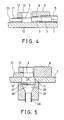
- Fig. 4 is a sectional view of the aligning unit along the line IV - IV of Fig. 3
- Fig. 5 is a sectional view of the aligning unit along the line V - V of Fig. 3
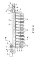
- Fig. 6 is a sectional view taken along the line VI - VI in Fig. 7
- Fig. 7 is a plan view of an aligning plate
- Fig. 8 is a sectional view of the aligning plate along the line VIII - VIII of Fig. 6
- Fig. 9 is a sectional view of a loading unit
- Fig. 10 is a perspective view of a tray. Best Mode of Carrying Out the Invention
- Fig. 1 schematically illustrates the overall arrangement of a small-article feed machine.
- This feed machine comprises a parts feeder unit 1.
- the parts feeder unit 1 comprises a single parts feeder or a plurality of parts feeders.
- the parts feeder unit 1 has, e.g., 12 parts feed ports 2. Note that only one parts feed port 2 is illustrated in Fig. 1.
- the parts feeder unit stores a large number of small articles each having two ends of different shapes, e.g., capsules 3 shown in Fig. 2 in this embodiment.
- the capsule 3 comprises a small cylindrical container made of a synthetic resin and having one closed end and the other open end.
- the closed end of the capsule 3 has a thin-walled portion which can open the closed end when its outer end wall is pushed by a finger to elastically deform the outer end wall.
- the thin-walled portion comprises a plurality of radial grooves 4.
- the parts feeder unit 1 has a function of sequentially feeding the capsules 3 from each parts feed port 2.
- the capsules 3 are fed from the parts feed port 2 such that the axial direction of the capsule 3 is aligned with its feed direction.
- first guide pipe path 5 indicated by the alternate long and short dashed line in Fig. 1 is connected to each parts feed port 2 of the parts feeder unit 1.
- the other end of the first guide pipe path 5 is connected to an aligning unit 6.
- the aligning unit 6 is located below the parts feeder unit 1.
- the capsule 3 fed out from each parts feed port 2 of the parts feeder unit 1 is guided to the aligning unit 6 through the first guide pipe path 5.
- the capsule 3 guided to the aligning unit 6 through the first guide pipe path 5 maintains its posture so that the closed or open end serves as a leading end.
- the aligning unit 6 is best illustrated in Figs. 3 to 5 and will be described below.
- the aligning unit 6 comprises a rectangular base plate 7 aligned in the horizontal direction.
- An inlet head 8 is disposed on the base plate 7.
- the inlet head 8 comprises a rectangular block member.
- the inlet head 8 has inlet paths 9, the number of which is equal to that of the first guide pipe path 5, i.e., 12 inlet paths 9. These inlet paths 9 are equidistantly arranged in the horizontally direction.
- Two ends of each inlet path 9 are open to corresponding two side surfaces of the inlet head 8.
- the other end of each first guide pipe path 5 is inserted into and connected to one end of the corresponding inlet path 9 on the parts feeder apparatus 1 side.
- a portion of the base plate 7 on the other-end side of the inlet path 9 constitutes an aligning plate 10.
- the aligning plate 10 has 12 passage openings 11 located at a position adjacent to the side surface of the inlet head 8, as shown in Figs. 3 and 5. Only three passage openings 11 are illustrated in Fig. 3, and only one passage opening 11 is illustrated in Fig. 5. Although these passage openings 11 are equidistantly aligned in the direction of an array of the inlet paths 9 of the inlet head 8, they are offset from the inlet paths 9 in the direction of the array of these inlet paths 9. In this embodiment, the passage openings 11 are offset from the inlet paths 9 by 1/2 pitches in the direction of the array of the inlet paths 9.
- Each passage opening 11 has a rectangular shape and a size enough to cause one capsule 3 aligned in the horizontal direction to pass therethrough.
- a slide head 12 is slidably arranged adjacent to the inlet head 8 on the aligning plate 10 so as to cover the passage openings 11.
- the slide head 12 comprises an elongated block member extending along the inlet head 8.
- the slide head 12 has 12 pockets 13 spaced apart from each other by a predetermined pitch in the same manner as the inlet paths 9 of the inlet head 8. These pockets 13 are constituted by rectangular notches open to the upper surface of the slide head 12 and the side surface of the inlet head 8. Each pocket 13 has a size enough to receive one capsule 3.
- Two end portions of the slide head 12 are mounted through arms 14 and 15 on a guide rod 16 extending parallel to the slide head 12.
- the slide head 12 is slidable along the guide rod 16.
- the arm 15 extends over the guide rod 16, and its distal end portion is slidably supported by a cantilevered guide rod 17.
- An air cylinder 19 constituting a slide head drive mechanism is mounted on a support base 18 which supports one end of each of the guide rods 16 and 17.
- a piston rod 20 of the air cylinder 19 is connected to the central portion of the arm 15.
- a stopper plate 21 extending along the slide head 12 is fixed on the aligning plate 10. As is apparent from Figs. 4 and 5, one edge of the stopper plate 21 is inserted into the slide head 12, so that one side surface of the stopper plate 21 constitutes part of the inner end face of the pocket 13 in the slide head 12.
- the leading capsule 3 fed by a push-push technique from the parts feeder unit 1 to each inlet path 9 of the inlet head 8 through the corresponding first guide path 5 is fed from the corresponding inlet path 9 to the corresponding pocket 13 of the slide head 12 and abuts against the stopper plate 21.
- a detector 22 for detecting the presence/absence of the capsule 3 in the guide pipe path 5 is arranged midway along each first guide pipe path 5.
- the detector 22 outputs a detection signal for stopping the operation of the slide head 12 when capsules 3 are absent from the first guide pipe path 5. That is, when this detection signal is output, the slide head 12 is moved to the discharge position, and its operation is stopped. Then, feeding of the capsule 3 from each inlet path 9 of the inlet head 8 to each pocket 13 of the slide head 12 is stopped.
- Each detector 23 comprises a discrimination sensor consisting of a light-emitting element and a light-receiving element.
- the detector 23 detects the axial direction of this capsule 3 and outputs a discrimination signal. That is, when the closed end of the capsule 3 in the pocket 13 opposes one side surface of the stopper plate 21, the detector 23 outputs a first discrimination signal. When the open end of the capsule opposes one side surface of the stopper plate 21, the detector 23 outputs a second discrimination signal.
- reception members 24 are arranged immediately below the corresponding passage openings 11 of the aligning plate 10.
- Reception holes 25 tapered toward their distal ends are formed in the reception members 24 in continuation with the corresponding passage openings 11.
- each reception hole 25 is a rectangular hole having a major axis aligned with that of the passage opening 11, as is apparent from Fig. 3.
- each reception hole 25 has two arcuated end portions, and the upper portion of the reception hole 25 is slightly larger than the passage opening 11.
- Second guide pipe paths 26 similar to the first guide pipe paths 5 are connected to the reception holes 25 of the reception members 24, respectively.
- pins 27 are fitted in the upper portions of the reception holes 25 of the reception members 24. Each pin 27 horizontally extends along the minor-axis direction of the reception holes 25. Two ends of the pin 27 are slidably inserted into slots 28 of the corresponding reception member 24. These slots 28 horizontally extend along the major-axis direction of the reception holes, so that the pin 27 can be moved in the major-axis direction of the reception hole 25.
- the pins 27 can be independently moved by air cylinders 29 constituting pin drive mechanisms in the major-axis direction of the reception holes 25. As is apparent from Fig. 3, one end of the pin 27 extends from the corresponding reception member 24. An extended end of the pin 27 is connected to a piston rod 30 of the corresponding air cylinder 29 paired with this piston rod 30. Each air cylinder 29 is operated in response to a discrimination signal from each detector 23. In this embodiment, when the capsule 3 is fed to one pocket 13 and the detector 23 of this pocket 13 outputs the first discrimination signal, the pin 27 in the reception member 24 paired with this pocket 13 is moved to a position indicated by the alternate long and short dashed line in Fig. 5. On the other hand, when the second discrimination signal is output, the pin 27 is moved by the corresponding air cylinder 29 to a position indicated by the solid line.
- Each pin 27 is positioned in accordance with the axial direction of the capsule 3 fed to each pocket 13.
- each pocket 13 of the slide head 12 which pocket 13 holds the capsule 3 is moved to a position where it is aligned with the corresponding passage opening 11 of the aligning plate 10.
- the capsule 3 of each pocket 13 drops from the pocket 13 into the reception hole 25 of the corresponding reception member 24 through the passage opening 11. In this case, the capsule 3 drops into the reception hole 25 while maintaining its horizontal posture.
- one end portion of each capsule i.e., its open end abuts against the pin 27 upon dropping.
- An outlet head 31 is horizontally arranged below the aligning unit 6. As is apparent from Fig. 6, the outlet head 31 has the same shape and structure as those of the inlet head 8. In this case, the outlet head 31 has 12 outlet paths 32 in place of the inlet paths 9. The outlet paths 32 are equidistantly arranged in the horizontal direction. One end of each outlet path 32 is inserted into and connected to the lower end of the corresponding second guide pipe path 26. The capsule 3 guided no each second guide pipe path 26 by the push-push technique is guided to the corresponding outlet path 32 of the outlet head 31 and can be fed out from the other end of this outlet path 32. A detector 33 similar to the detector 22 is arranged midway along each second guide pipe path 26.
- An aligning plate 34 is horizontally arranged adjacent to the outlet head 31 on the other-end side of the outlet path 32 in the outlet head 31.
- the aligning plate 34 has an almost square shape and has 12 reception grooves 35. These reception grooves 35 are bottomless notched grooves and correspond to the 12 outlet paths 32 of the outlet head 31.
- the reception grooves 35 are parallel to each other and are spaced apart from the side surface of the outlet head 31 at the aligning plate 34.
- a drop plate 36 is arranged immediately below the aligning plate 34.
- the drop plate 36 constitutes a bottom wall of the reception grooves 35 and is held to be slidable in a direction indicated by an arrow A in Fig. 6. That is, as is apparent from Fig. 8, a pair of guide plates 37 each having an L-shaped section are arranged on both sides of the plate 36 in the direction indicated by the arrow A.
- Guide rollers 38 for guiding the drop plate 36 in the direction indicated by the arrow A are rotatably mounted on the inner surfaces of these guide plates 37.
- a piston rod 40 of an air cylinder 39 constituting a drop plate drive mechanism is connected to an edge of the drop plate 36 on the outlet head 31 side.
- the drop plate 36 is moved between a holding position where it serves as the bottom wall of the reception grooves 35 in the aligning plate 34 and a drop position where the drop plate 36 is shifted from the reception grooves 35.
- the capsules 3 discharged from each outlet path 32 of the outlet head 31 are sequentially supplied to the corresponding reception groove 35 of the aligning plate 34 in an array.
- a stopper 41 is arranged on the inner wall side of the reception groove 35 in the aligning plate 34. As shown in Fig. 8, this stopper 41 comprises a plate member having a comb-like lower surface. The teeth of the stopper 41 are respectively inserted in the reception grooves 35 so as to be meshed with them. The first capsule 3 inserted into the reception groove 35 is moved forward toward the stopper 41 since additional capsules 3 are subsequently fed to this reception groove 35. The first capsule 3 then abuts against the stopper 41. When the leading capsule 3 abuts against the stopper 41, the 12 capsules 3 are stored in each reception groove 35 in a line.
- a detector mounting member 42 (Fig. 6) which abuts against the stopper 41 is arranged to bridge over the twelve reception grooves 35.
- the detector mounting member 42 has a gate-like shape, and its two legs are supported on the aligning plate 34.
- a total of twelve detectors 43 are mounted on the detector mounting member 42 in correspondence with the reception grooves 35. These detectors 43 have the same arrangements as those of the detectors 22 and 33.
- Each detector 43 detects whether the capsule 3 is present immediately below the detector 43, i.e., whether the leading capsule 3 in the reception groove 35 abuts against the stopper 41.
- the detector 43 outputs its detection signal.
- Each detector 43 prevents feeding of the capsules 3 into an abutment in which the leading capsule 3 is in contact with the stopper 41.
- the stopper 41 is connected to a piston rod 49 of an air cylinder 48. Upon driving of the piston rod 49 of the air cylinder 48, the stopper 41 is movable in a direction to be separated from the detector mounting member 42.
- a matrix plate 50 is arranged immediately below the drop plate 36 held in the holding position so as to be clamped between the pair of guide plates 37.
- the matrix plate 50 has a total of 144 drop openings 51 corresponding to the capsules 3 in the respective reception grooves 35.
- Each drop opening 51 has a rectangular shape enough to cause the capsule 3 to pass therethrough.
- the size of the drop opening 51 is gradually reduced downward. That is, as shown in Fig. 6, the inner end wall located on the outlet head 31 side in each drop opening 51 forms an inclined wall 52.
- each drop opening 51 of the matrix plate 50 is slightly shifted toward the stopper 41 in the direction of the reception grooves 35 with respect to the corresponding capsules 3 stored in the reception grooves 35.
- a drop pipe path 53 similar to the guide pipe paths 5 and 26 is connected to the lower end of each drop opening 51 in the matrix plate 50.
- the lower end of each drop pipe path 53 is mounted on a loading plate 55 arranged in the horizontal direction. That is, 144 through holes 56 arranged in a matrix form are formed in the loading plate 55.
- the lower end of each drop pipe path 53 is inserted into and connected to the upper portion of the corresponding through hole 56.
- a loading unit for the capsules 3 is arranged below the loading plate 55.
- the loading unit has a lift 57.
- the lift 57 is connected to a piston rod 59 of a lift cylinder 58 consisting of an air cylinder.
- the lift 57 is vertically moved upon driving of the piston rod 59 of the lift cylinder 58.
- Reference numeral 60 in Fig. 9 denotes a support member for supporting the lift cylinder 58.
- the lift 57 constitutes part of a conveyor 62 for conveying a tray 61.
- the conveyor 62 extends to pass below the loading plate 55.
- the lift 57 therefore has guide rollers 63 similar to the guide rollers constituting the conveyor 62.
- the lift 57 When the lift 57 is located at a lower position shown in Fig. 9, i.e., the lift 57 has the same level as that of the conveyor 62, the lift 57 constitutes part of the conveyor 62.
- the tray 61 conveyed along the conveyor 62 can be transferred onto the lift 57.
- conveyance of the tray 61 is stopped. That is, in order to appropriately transfer the tray 61 onto the lift 57, a stopper lever 64 is arranged at the leading edge of the lift 57 when viewed along the convey direction of the tray 61.
- the central portion of the stopper lever 64 is pivotally mounted on a bracket 65 fixed on the support member 60.
- a coil spring 68 is hooked between the lower end of the stopper lever 64 and a pracket 65.
- the upper end of the stopper lever 64 extends above the upper surface of the lift 57 through a notch 67 of the lift 57.
- a lock member 69 for abutting against the lower end of the stopper lever 64 and limiting clockwise pivotal movement of the stopper lever 64 is mounted on the support member 60.
- a detector 70 consisting of a limit switch is mounted on the lock member 69 to detect whether the stopper lever 64 abuts against the lock member 69.
- a detector 71 for detecting a pivotal position of the stopper lever 64 is mounted on the support member 60, as needed.
- the detector 71 is arranged to oppose the lower end of the stopper lever 64 and has a function of optically detecting the pivotal posture of the stopper lever 64, i.e., a function of optically detecting whether the stopper lever 64 is located at an angular position shown in Fig. 9.
- the tray 61 when the tray 61 is conveyed along the conveyor 62 and is then transferred onto the lift 57, the tray 61 is further moved on the lift 57 along the convey direction.
- the tray 61 abuts against the upper end of the stopper lever 64 and pivots the stopper lever 64 clockwise.
- pivotal movement of the stopper lever 64 is limited, and movement of the tray 61 on the lift 57 is stopped.
- the tray 61 is held on the lift 57.
- conveyance of the next tray 61 along the conveyor 62 is stopped.
- 144 storage holes 73 capable of receiving the capsules 3 in an upright posture are formed in the tray 61 in the same matrix form as that of the through holes 56 formed in the loading plate 55.
- the storage holes 73 in the tray 61 are aligned with the corresponding through holes 56 in the loading plate 55. At this time, preparation for loading the capsules 3 on the tray 61 is completed.
- the stopper plate 41 in the aligning capsule 34 is separated from the detector mounting member 42, as indicated by the alternate long and short dashed line in Fig. 6, and then the air cylinder 39 are contracted.
- the drop plate 36 is moved to a position offset from the lower portion of the aligning plate 34.
- the capsules 3 already received in a line in the reception grooves 35 sequentially drop into the corresponding drop openings 50 of the matrix plate 50 from the leading capsules 3.
- the capsules are then loaded from the drop openings 50 to the corresponding storage holes 73 of the tray 61 through the drop pipe paths 53 and the through holes 56 of the loading plate 55.
- the capsules 3 can accurately drop so that their closed ends are leading ends when the capsules 3 pass through the corresponding drop openings 51.
- the drop plate 36 returns to the holding position.
- the stopper plate 41 also returns to a position where it abuts against the detector mounting member 42. Therefore, new capsules 3 are fed out from the outlet head 31 to the reception grooves 35 of the aligning plate 34, thereby aligning the capsules 3 in lines.
- the tray 61 loaded with the capsules 3 is moved downward while the lift 57 is moved downward to the lower position. In this case, the tray 61 abuts against the upper end of the stopper lever 64 to pivot the stopper lever 64 counterclockwise.
- the tray 61 on the lift 57 is not engaged with the stopper lever 64 and is pushed by an empty tray 61 in the downstream of the conveyor 62 from the lift 57. The next step is then started.
- the empty tray 61 is moved by the lift 57 upward immediately below the loading plate 55.
- the above operations are repeated to load the capsules 3 into the empty tray.
- a predetermined liquid is filled in the capsules 3 loaded on the tray 61, and the open ends of the capsules are closed by seals (not shown) in a liquid-tight state.
- small articles in an aligned state can be fed to the next step.
- the movable member only the drop plate, and its structure can be simplified.
- its operation reliability can be improved. Feeding of small articles in an aligned state can be almost simultaneously performed, and feed efficiency of small articles can be improved, thus providing many advantages.
Landscapes
- Engineering & Computer Science (AREA)
- Manufacturing & Machinery (AREA)
- Microelectronics & Electronic Packaging (AREA)
- Mechanical Engineering (AREA)
- Feeding Of Articles To Conveyors (AREA)
- Branching, Merging, And Special Transfer Between Conveyors (AREA)
- Automatic Assembly (AREA)
Abstract
Applications Claiming Priority (3)
| Application Number | Priority Date | Filing Date | Title |
|---|---|---|---|
| JP152256/89 | 1989-06-16 | ||
| JP1152256A JP2502375B2 (ja) | 1989-06-16 | 1989-06-16 | 小物部品の供給機 |
| PCT/JP1990/000789 WO1990015765A1 (fr) | 1989-06-16 | 1990-06-16 | Appareil d'amenee de petites pieces |
Publications (3)
| Publication Number | Publication Date |
|---|---|
| EP0429669A1 true EP0429669A1 (fr) | 1991-06-05 |
| EP0429669A4 EP0429669A4 (en) | 1991-07-31 |
| EP0429669B1 EP0429669B1 (fr) | 1994-12-21 |
Family
ID=15536508
Family Applications (1)
| Application Number | Title | Priority Date | Filing Date |
|---|---|---|---|
| EP90909361A Expired - Lifetime EP0429669B1 (fr) | 1989-06-16 | 1990-06-16 | Appareil d'amenee de petites pieces |
Country Status (5)
| Country | Link |
|---|---|
| US (1) | US5102009A (fr) |
| EP (1) | EP0429669B1 (fr) |
| JP (1) | JP2502375B2 (fr) |
| DE (1) | DE69015329T2 (fr) |
| WO (1) | WO1990015765A1 (fr) |
Cited By (3)
| Publication number | Priority date | Publication date | Assignee | Title |
|---|---|---|---|---|
| EP0601221A1 (fr) * | 1992-12-01 | 1994-06-15 | Frisco-Findus Ag | Dispositif de préhension |
| EP0812787A1 (fr) * | 1996-06-13 | 1997-12-17 | Erbengemeinschaft Peter Hofsäss: Hofsäss, U. Hofsäss, M.P. Hofsäss, D.P. Hofsäss, H.P. Hofsäss, C.R. Hofsäss, B.M. | Méthode et dispositif pour aligner des bonnets rétractables pour thermocontrÔleurs |
| WO2002003412A1 (fr) * | 2000-06-30 | 2002-01-10 | General Electric Company | Procede et dispositif de chargement d'extremite d'electrode |
Families Citing this family (14)
| Publication number | Priority date | Publication date | Assignee | Title |
|---|---|---|---|---|
| US5325956A (en) * | 1993-02-24 | 1994-07-05 | Philip Morris Incorporated | Method and apparatus for orienting elongated components with distinct ends |
| DE4312526A1 (de) * | 1993-02-27 | 1994-09-01 | Werner Hermann Wera Werke | Zuführeinrichtung an Werkzeugmaschinen, insbesondere zur Endbearbeitung von Schraubendreher-Bits |
| US5353913A (en) * | 1993-09-30 | 1994-10-11 | United Bakery Equipment Company | Packaging machine for bakery products |
| US5579951A (en) * | 1994-06-23 | 1996-12-03 | Bayer Corporated | Apparatus for orienting and loading solid compact medicaments |
| US20060185149A1 (en) * | 2005-02-18 | 2006-08-24 | Rodney Erdman | Screw feeder |
| US20080135464A1 (en) * | 2006-10-17 | 2008-06-12 | Lubezny Vadim A | Separating system for separating articles |
| JP2008224965A (ja) * | 2007-03-12 | 2008-09-25 | Ricoh Co Ltd | 光走査装置、および画像形成装置 |
| JP6057746B2 (ja) * | 2013-01-31 | 2017-01-11 | セイコーインスツル株式会社 | フェルール搬送装置、フェルール分類装置、フェルール搬送方法、フェルール搬送プログラム及び記録媒体 |
| CN103601605B (zh) * | 2013-11-09 | 2016-01-20 | 河北科技大学 | 一种雷管生产中雷管组合模的自动备料装置 |
| CN103601607B (zh) * | 2013-11-09 | 2015-12-02 | 河北科技大学 | 一种雷管管壳自动调向机构 |
| JP6451995B2 (ja) * | 2015-07-15 | 2019-01-16 | 青山 省司 | 突起付き部品の通路部材およびパーツフィーダ |
| CN105059883A (zh) * | 2015-08-12 | 2015-11-18 | 苏州佳像视讯科技有限公司 | 一种电子元器件自动上料用进料板 |
| CN107837832B (zh) * | 2017-11-13 | 2020-01-17 | 贵州金域医学检验中心有限公司 | 一种快速导入枪头的便携装置盒 |
| EP3617813B1 (fr) * | 2018-09-03 | 2025-02-26 | Rolex Sa | Dispositif de transfert de composants horlogers |
Family Cites Families (16)
| Publication number | Priority date | Publication date | Assignee | Title |
|---|---|---|---|---|
| US1325752A (en) * | 1919-12-23 | sheets | ||
| GB599845A (en) * | 1945-08-30 | 1948-03-22 | Jonkopings Och Vulcans Tandsti | Improved method and device for arranging and packing disordered articles |
| GB576559A (en) * | 1942-06-02 | 1946-04-10 | Marconi Wireless Telegraph Co | Improvements in or relating to mechanism for feeding short lengths of wire |
| US3526743A (en) * | 1967-05-26 | 1970-09-01 | Trw Inc | Apparatus for dispensing studs to plural welding tools |
| US3942645A (en) * | 1969-06-26 | 1976-03-09 | Eli Lilly And Company | Feeding and rectifying apparatus and method |
| JPS5132208Y2 (fr) * | 1971-05-06 | 1976-08-11 | ||
| JPS49115664A (fr) * | 1973-03-07 | 1974-11-05 | ||
| JPS5296195A (en) * | 1976-02-04 | 1977-08-12 | Osaka Jidouki Seisakushiyo Kk | Rotary apparatus for reeorientating and charging capsules |
| JPS52137864A (en) * | 1976-05-12 | 1977-11-17 | Meiji Seika Co | Row arranging conveyor for bars |
| JPS52147867A (en) * | 1976-06-01 | 1977-12-08 | Shinko Electric Co Ltd | Device for regulating and supplying in order all the parts fed |
| IT1101040B (it) * | 1978-11-09 | 1985-09-28 | Facchini Libero | Orientatore di capsule,particolarmente per macchine opercolatrici |
| US4362234A (en) * | 1980-10-06 | 1982-12-07 | Mcdonald Walter | High speed cap orienting and feeding apparatus |
| JPS60197513A (ja) * | 1984-03-17 | 1985-10-07 | Nitto Kogyo Kk | 固形物の送給装置 |
| JPH0729689B2 (ja) * | 1985-05-10 | 1995-04-05 | 日本ニユクリア・フユエル株式会社 | 柱状物体の列形成装置 |
| EP0207341B1 (fr) * | 1985-07-05 | 1989-11-23 | Dynamit Nobel Aktiengesellschaft | Dispositif pour aligner les côtés ouverts de douilles |
| US4828142A (en) * | 1986-01-24 | 1989-05-09 | Eli Lilly & Company | Capsule rectification apparatus |
-
1989
- 1989-06-16 JP JP1152256A patent/JP2502375B2/ja not_active Expired - Lifetime
-
1990
- 1990-06-16 EP EP90909361A patent/EP0429669B1/fr not_active Expired - Lifetime
- 1990-06-16 WO PCT/JP1990/000789 patent/WO1990015765A1/fr not_active Ceased
- 1990-06-16 DE DE69015329T patent/DE69015329T2/de not_active Expired - Fee Related
- 1990-06-16 US US07/640,359 patent/US5102009A/en not_active Expired - Lifetime
Cited By (4)
| Publication number | Priority date | Publication date | Assignee | Title |
|---|---|---|---|---|
| EP0601221A1 (fr) * | 1992-12-01 | 1994-06-15 | Frisco-Findus Ag | Dispositif de préhension |
| EP0812787A1 (fr) * | 1996-06-13 | 1997-12-17 | Erbengemeinschaft Peter Hofsäss: Hofsäss, U. Hofsäss, M.P. Hofsäss, D.P. Hofsäss, H.P. Hofsäss, C.R. Hofsäss, B.M. | Méthode et dispositif pour aligner des bonnets rétractables pour thermocontrÔleurs |
| WO2002003412A1 (fr) * | 2000-06-30 | 2002-01-10 | General Electric Company | Procede et dispositif de chargement d'extremite d'electrode |
| US6446783B1 (en) | 2000-06-30 | 2002-09-10 | General Electric Company | Electrode tip loading method and apparatus |
Also Published As
| Publication number | Publication date |
|---|---|
| DE69015329T2 (de) | 1995-05-18 |
| US5102009A (en) | 1992-04-07 |
| EP0429669B1 (fr) | 1994-12-21 |
| JP2502375B2 (ja) | 1996-05-29 |
| JPH0318509A (ja) | 1991-01-28 |
| EP0429669A4 (en) | 1991-07-31 |
| DE69015329D1 (de) | 1995-02-02 |
| WO1990015765A1 (fr) | 1990-12-27 |
Similar Documents
| Publication | Publication Date | Title |
|---|---|---|
| US5102009A (en) | Small-article feed machine | |
| US5141128A (en) | Reconfigurable vertical conveyor dispenser | |
| US6368872B1 (en) | Apparatus and method for chemical processing | |
| DK2018528T3 (en) | Method and system for batch formation of objects | |
| US10173830B2 (en) | Medication dispensing container | |
| NL1004095C1 (nl) | Werkwijze en inrichting voor het aanvoeren en plaatsen van componenten. | |
| CN109533474B (zh) | 存放设备 | |
| KR900005674B1 (ko) | 봉상물의 충진장치 | |
| US6805528B2 (en) | Apparatus for replacing rejected articles, in particular blister packs, in a feeding line of a packaging machine | |
| JP2004538222A (ja) | バラ積み容器供給装置 | |
| US5810061A (en) | Drug dispenser and method for dispensing drug | |
| JPH068128B2 (ja) | 巻たばこを巻たばこマガジンから取出しかつ無端コンベヤへ移送する装置 | |
| CN113716111A (zh) | 用于转移产品的方法和组件 | |
| CA1077070A (fr) | Distribution en files de contenants cylindriques a partir d'un chemin de deversement | |
| JP7809365B2 (ja) | トレイ供給装置および卵の選別装置 | |
| JP2021011325A (ja) | 物品移載装置 | |
| JP3057368B1 (ja) | ピッキング装置 | |
| JP3618227B2 (ja) | 農産物選別装置における空箱供給装置 | |
| ES2919656T3 (es) | Detección de metales mejorada y ampliada en pesadoras multicabezal | |
| JP3132439U (ja) | 卵の選別包装装置 | |
| EP4408373B1 (fr) | Appareil et procédé d'alimentation en capsules | |
| JP2571934B2 (ja) | 円筒状容器の振分け供給装置 | |
| JP2768591B2 (ja) | 錠剤の分包処理装置 | |
| JP2000313520A (ja) | 長尺テーパ状の中空成型物のフィーダ装置及び長尺テーパ状の中空成型物を小出しに供給する方法 | |
| KR0143332B1 (ko) | 반도체소자 검사기용 벌크 로더 |
Legal Events
| Date | Code | Title | Description |
|---|---|---|---|
| PUAI | Public reference made under article 153(3) epc to a published international application that has entered the european phase |
Free format text: ORIGINAL CODE: 0009012 |
|
| 17P | Request for examination filed |
Effective date: 19910122 |
|
| AK | Designated contracting states |
Kind code of ref document: A1 Designated state(s): CH DE GB IT LI |
|
| A4 | Supplementary search report drawn up and despatched |
Effective date: 19910612 |
|
| AK | Designated contracting states |
Kind code of ref document: A4 Designated state(s): CH DE GB IT LI |
|
| 17Q | First examination report despatched |
Effective date: 19921209 |
|
| GRAA | (expected) grant |
Free format text: ORIGINAL CODE: 0009210 |
|
| AK | Designated contracting states |
Kind code of ref document: B1 Designated state(s): CH DE GB IT LI |
|
| ITF | It: translation for a ep patent filed | ||
| REF | Corresponds to: |
Ref document number: 69015329 Country of ref document: DE Date of ref document: 19950202 |
|
| PLBE | No opposition filed within time limit |
Free format text: ORIGINAL CODE: 0009261 |
|
| STAA | Information on the status of an ep patent application or granted ep patent |
Free format text: STATUS: NO OPPOSITION FILED WITHIN TIME LIMIT |
|
| 26N | No opposition filed | ||
| PGFP | Annual fee paid to national office [announced via postgrant information from national office to epo] |
Ref country code: CH Payment date: 19980525 Year of fee payment: 9 |
|
| PGFP | Annual fee paid to national office [announced via postgrant information from national office to epo] |
Ref country code: GB Payment date: 19980608 Year of fee payment: 9 |
|
| PGFP | Annual fee paid to national office [announced via postgrant information from national office to epo] |
Ref country code: DE Payment date: 19980819 Year of fee payment: 9 |
|
| PG25 | Lapsed in a contracting state [announced via postgrant information from national office to epo] |
Ref country code: GB Free format text: LAPSE BECAUSE OF NON-PAYMENT OF DUE FEES Effective date: 19990616 |
|
| PG25 | Lapsed in a contracting state [announced via postgrant information from national office to epo] |
Ref country code: LI Free format text: LAPSE BECAUSE OF NON-PAYMENT OF DUE FEES Effective date: 19990630 Ref country code: CH Free format text: LAPSE BECAUSE OF NON-PAYMENT OF DUE FEES Effective date: 19990630 |
|
| GBPC | Gb: european patent ceased through non-payment of renewal fee |
Effective date: 19990616 |
|
| REG | Reference to a national code |
Ref country code: CH Ref legal event code: PL |
|
| PG25 | Lapsed in a contracting state [announced via postgrant information from national office to epo] |
Ref country code: DE Free format text: LAPSE BECAUSE OF NON-PAYMENT OF DUE FEES Effective date: 20000503 |
|
| PG25 | Lapsed in a contracting state [announced via postgrant information from national office to epo] |
Ref country code: IT Free format text: LAPSE BECAUSE OF NON-PAYMENT OF DUE FEES;WARNING: LAPSES OF ITALIAN PATENTS WITH EFFECTIVE DATE BEFORE 2007 MAY HAVE OCCURRED AT ANY TIME BEFORE 2007. THE CORRECT EFFECTIVE DATE MAY BE DIFFERENT FROM THE ONE RECORDED. Effective date: 20050616 |