EP0429766B1 - Geräte und Verfahren zur Hakenmarkierung und Erkennung in elektrischen Motoren - Google Patents
Geräte und Verfahren zur Hakenmarkierung und Erkennung in elektrischen Motoren Download PDFInfo
- Publication number
- EP0429766B1 EP0429766B1 EP90116086A EP90116086A EP0429766B1 EP 0429766 B1 EP0429766 B1 EP 0429766B1 EP 90116086 A EP90116086 A EP 90116086A EP 90116086 A EP90116086 A EP 90116086A EP 0429766 B1 EP0429766 B1 EP 0429766B1
- Authority
- EP
- European Patent Office
- Prior art keywords
- hook
- hook member
- armature
- force
- predetermined
- Prior art date
- Legal status (The legal status is an assumption and is not a legal conclusion. Google has not performed a legal analysis and makes no representation as to the accuracy of the status listed.)
- Expired - Lifetime
Links
- 238000000034 method Methods 0.000 title claims abstract description 27
- 238000012545 processing Methods 0.000 claims description 31
- 238000006073 displacement reaction Methods 0.000 claims description 28
- 238000012544 monitoring process Methods 0.000 claims 6
- 238000004804 winding Methods 0.000 abstract description 31
- 238000012546 transfer Methods 0.000 description 5
- 230000008569 process Effects 0.000 description 4
- WABPQHHGFIMREM-UHFFFAOYSA-N lead(0) Chemical compound [Pb] WABPQHHGFIMREM-UHFFFAOYSA-N 0.000 description 3
- 230000004044 response Effects 0.000 description 3
- 230000002159 abnormal effect Effects 0.000 description 2
- 230000008901 benefit Effects 0.000 description 2
- 230000004927 fusion Effects 0.000 description 2
- 238000005259 measurement Methods 0.000 description 2
- 230000009471 action Effects 0.000 description 1
- 239000012190 activator Substances 0.000 description 1
- 238000010586 diagram Methods 0.000 description 1
- 230000005611 electricity Effects 0.000 description 1
- 238000004070 electrodeposition Methods 0.000 description 1
- 238000009413 insulation Methods 0.000 description 1
- 230000007246 mechanism Effects 0.000 description 1
- 238000013519 translation Methods 0.000 description 1
Images





Classifications
-
- H—ELECTRICITY
- H02—GENERATION; CONVERSION OR DISTRIBUTION OF ELECTRIC POWER
- H02K—DYNAMO-ELECTRIC MACHINES
- H02K15/00—Processes or apparatus specially adapted for manufacturing, assembling, maintaining or repairing of dynamo-electric machines
- H02K15/08—Forming windings by laying conductors into or around core parts
- H02K15/09—Forming windings by laying conductors into or around core parts by laying conductors into slotted rotors
-
- Y—GENERAL TAGGING OF NEW TECHNOLOGICAL DEVELOPMENTS; GENERAL TAGGING OF CROSS-SECTIONAL TECHNOLOGIES SPANNING OVER SEVERAL SECTIONS OF THE IPC; TECHNICAL SUBJECTS COVERED BY FORMER USPC CROSS-REFERENCE ART COLLECTIONS [XRACs] AND DIGESTS
- Y10—TECHNICAL SUBJECTS COVERED BY FORMER USPC
- Y10T—TECHNICAL SUBJECTS COVERED BY FORMER US CLASSIFICATION
- Y10T29/00—Metal working
- Y10T29/49—Method of mechanical manufacture
- Y10T29/49002—Electrical device making
- Y10T29/49004—Electrical device making including measuring or testing of device or component part
-
- Y—GENERAL TAGGING OF NEW TECHNOLOGICAL DEVELOPMENTS; GENERAL TAGGING OF CROSS-SECTIONAL TECHNOLOGIES SPANNING OVER SEVERAL SECTIONS OF THE IPC; TECHNICAL SUBJECTS COVERED BY FORMER USPC CROSS-REFERENCE ART COLLECTIONS [XRACs] AND DIGESTS
- Y10—TECHNICAL SUBJECTS COVERED BY FORMER USPC
- Y10T—TECHNICAL SUBJECTS COVERED BY FORMER US CLASSIFICATION
- Y10T29/00—Metal working
- Y10T29/49—Method of mechanical manufacture
- Y10T29/49002—Electrical device making
- Y10T29/49009—Dynamoelectric machine
- Y10T29/49011—Commutator or slip ring assembly
-
- Y—GENERAL TAGGING OF NEW TECHNOLOGICAL DEVELOPMENTS; GENERAL TAGGING OF CROSS-SECTIONAL TECHNOLOGIES SPANNING OVER SEVERAL SECTIONS OF THE IPC; TECHNICAL SUBJECTS COVERED BY FORMER USPC CROSS-REFERENCE ART COLLECTIONS [XRACs] AND DIGESTS
- Y10—TECHNICAL SUBJECTS COVERED BY FORMER USPC
- Y10T—TECHNICAL SUBJECTS COVERED BY FORMER US CLASSIFICATION
- Y10T29/00—Metal working
- Y10T29/53—Means to assemble or disassemble
- Y10T29/5313—Means to assemble electrical device
- Y10T29/53143—Motor or generator
- Y10T29/53157—Means to stake wire to commutator or armature
-
- Y—GENERAL TAGGING OF NEW TECHNOLOGICAL DEVELOPMENTS; GENERAL TAGGING OF CROSS-SECTIONAL TECHNOLOGIES SPANNING OVER SEVERAL SECTIONS OF THE IPC; TECHNICAL SUBJECTS COVERED BY FORMER USPC CROSS-REFERENCE ART COLLECTIONS [XRACs] AND DIGESTS
- Y10—TECHNICAL SUBJECTS COVERED BY FORMER USPC
- Y10T—TECHNICAL SUBJECTS COVERED BY FORMER US CLASSIFICATION
- Y10T29/00—Metal working
- Y10T29/53—Means to assemble or disassemble
- Y10T29/5313—Means to assemble electrical device
- Y10T29/53143—Motor or generator
- Y10T29/53161—Motor or generator including deforming means
Definitions
- the present invention relates to armature winding machines, and, more particularly, to machines for winding the armature wires of an electric motor to a hook member ("tang") of a commutator bar and deforming selected hook members for later identification during processing.
- the conditions required for fusing commutator hooks vary depending upon the number of armature lead wires that are passed around a given hook.
- the fusing conditions must be tailored to the hook's winding configuration if a satisfactory fusion joint is to be formed. For example, a hook with a single wire passed around it will require a different electrode displacement, electrode force, and electric current application than a hook with two wires passed around it.
- the hook wrapped with two wires may require additional electrode force to produce a cohesion joint of satisfactory quality.
- Winding machines typically attach two armature lead wires to selected hooks during the termination stages of armature winding. At the instant a hook is wrapped with two wires, the armature has a precise, known angular position. Thus, it would be possible to transfer a wound armature to a fusing machine while in a known angular position. The hooks wrapped with two wires could be recognized by their angular position and appropriately processed. However, such a solution requires costly changes to the transfer solutions between the winding and fusing machines.
- a machine for processing the hook such as a fusing machine, which includes a force transducer for accurately determining the electrode displacement.
- the electrode force and displacement measurements will vary, depending upon whether or not the electrode is operating on a hook that was deformed by the winding machine.
- a microprocessor-based control system receives force and displacement data from the load cell and encoder, respectively, and acts on a motor to modify those quantities.
- the microprocessor recognises hooks that were previously deformed by the winding machine, and causes the fusing machine to execute a predetermined operation. The operation performed on a deformed hook may be different than the operation performed on a non-deformed hook.
- the microprocessor stores a distinct, predetermined electrode displacement or force function for fusing each hook variation that the apparatus can process. Electrode position or force may be continuously measured and adjusted according to the appropriate function.
- the apparatus applied current to the electrode when the electrode has a predetermined displacement or force, and may vary the current application according to whether or not the hook under operation was deformed (marked) by the winding machine.
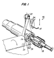
- FIGS. 1-8 illustrate the process for winding a lead wire 10 of an armature to a commutator bar 12.
- Wire 10 is wrapped around a hook 14 on commutator bar 12.
- a two-flyer winding machine 16 removes wire 10 from a coil and passes it around hook 14.
- An unwound armature 18 rests on winding machine 16 in winding receiving position.
- Wire 10 passes around a roller 20 and then around a flyer 22.
- Wire 10 stretches from flyer 22 to a gripper 24.
- Gripper 24 reciprocates during winding to draw wire 10 from a supply roll and over roller 20 and flyer 22.
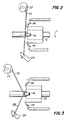
- the gripper's reciprocating action attaches the wire lead to hook 14 (FIG. 2).
- Initial and final leads are attached to the appropriate hooks and then cut by the operation of flyer 22, gripper 24, a cutter, and other equipment.
- start lead 26 (FIG. 3) is attached to the armature around a first hook by rotation of flyer 22. Wire 10 is then cut (see FIGS. 4 and 4a) between hook 14 and gripper 24 (near the hook) to free gripper 24 and leave start lead 26 wrapped around the hook.
- Flyer 22 and other equipment then operate to wind wire coils in the appropriate armature slots, and to loop the wire around the respective hooks.
- a single wire is passed around each hook (see FIG. 5) when the coils are being wound. The continuity of the wire is not interrupted.
- flyer 22 When flyer 22 has completed winding all of the coils that must be wound, a stretch of wire extends from the flyer to the last wound coil. Flyer 22 and other equipment then operate to loop the finish lead 28 around the last hook (see FIG. 6). Gripper 24 grips the stretch of wire leading from the hook to the flyer, and the wire is severed at a point near the hook. A new armature may then be wound.
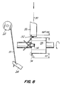
- FIG. 7a shows the start and finish leads of the two flyers wrapped behind the same hook.
- the start and finish leads may be on a hook which is also wrapped with an uninterrupted lead (FIG. 7b).
- the armature is rotated with the same equipment used to hold and rotate the armature during winding.
- the hooks wrapped with more than one wire are positioned under a deforming member 30.
- Deforming member 30 is displaced a predetermined distance along the deforming axis 31 to deform the hooks wrapped with two wires.
- Member 30 is driven by numerically-controlled axial actuators for high precision operations or when more than one deformed position is required. When less precision is required, conventional, less complex actuators can be used to drive deforming member 30.
- a plurality of deforming members may be used to increase operating speed.
- the deformed hooks 32 are bent towards the commutator bar 33.
- Deforming member 30 typically may be part of the winding apparatus. Hook 32 may be deformed while still in its winding position with a known angular position. Alternatively, the deforming step may be performed by a machine (FIG. 9) that unloads the armature from winding machine 16 and places it on a transfer mechanism. The armature is removed from the winding machine and positioned beneath deforming member 30. An activator 34 controls a collet 35, which releasably holds the shaft of the armature in a known angular position. A shuttle 36 is moved by member 37 along guides 38 to withdraw the armature from winding machine 16, positioning the armature adjacent deforming member 30. After member 30 marks the appropriate hook, the armature may be transferred to other equipment for further processing.
- deformed hook 32 has a different position, relative to commutator bar 33, than the upper surface of non-deformed hooks 14.
- Apparatus that is sensitive to force exerted on a translating member, or which can detect the displacement of a translating member along an axis of translation, is used to distinguish deformed hooks 32 (wrapped with several wires) from non-deformed hooks 14 (wrapped with a single wire). In this manner, subsequent processing equipment, such as a fusing machine, can automatically identify hooks wrapped with more than one wire.
- Distinguishing between the commutator hooks wrapped with more than one wire and hooks wrapped with a single wire enables the fusing machine to perform a different fusing operation on each type of hook.
- Deforming hooks during the winding operation offers the additional advantage of exerting additional pressure on the wrapped wires. This aids in holding the wires under the hook during subsequent transfer and handling of the armature.
- Fusing machines capable of recognizing hooks deformed during the winding operation typically include one or more sensing elements.
- the sensing elements measure force exerted on a hook as a function of time or as a function of fusing electrode displacement. Alternatively, the sensing elements detect electrode displacement as a function of time or electrode force.
- Fusing apparatus suitable for this purpose is described in commonly owned, co-pending U.S. patent No. 5063279.
- the fusing operation may be tailored to the condition of the particular hook being fused. This permits a better fusion joint to be produced.
- the heat i.e., electric current
- force applied to the hooks, and the displacement performance of the electrode are tailored to obtain the ideal fusing condition, which results in the correct electrical resistance and sufficient mechanical resistance of the connection.
- a fusing electrode typically must generate more heat to fuse a hook wrapped with two wires in order to remove the greater quantity of wire insulation. The extra heat must be combined with the appropriate force and displacement performance of the electrode.
- FIG. 10 shows a fusing machine in which the rotational motion of a motor 40 is converted into translational motion of fusing electrode 42 along axis 31.
- a rotation of motor output drive shaft 44 will cause a ball screw 46 to rotate.
- the engagement of ball screw 46 with sleeve 48 causes hollow member 50, hollow member 52, and electrode 42 to translate along electrode axis 31.
- a roller 54 maintains the alignment of hollow members 50 and 52 along axis 31.
- a force transducer such as load cell 56
- a space 58 allows hollow member 52 to translate along hollow member 50, and allows load cell 56 to deform correspondingly.
- a mass electrode 60 contacts the commutator during fusing to provide a current sink for electricity flowing from electrode 42.
- the fusing machine can monitor and adjust the electrode displacement and force.
- the displacement is derived, using encoder 62, from the number of turns of motor drive shaft 44.
- Load cell 56 measures the force resistance against the electrode.
- Microprocessor circuit 66 acts in response to data received from either the encoder or the load cell.
- Microprocessor circuit 66 causes the motor to precisely lower (or raise) electrode 42.
- the microprocessor changes the field conditions of motor 40 to control the motor's torque.
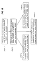
- the apparatus can be used to implement the feedback loops shown in FIGS. 12 and 13, to distinguish deformed hooks from non-deformed hooks, and to perform a different processing operation on each type of hook.
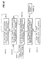
- a feedback measurement loop provides a means for displacing a fusing electrode of a fusing machine a predetermined distance, corresponding to a position slightly below the upper surface of a non-deformed hook (step A).
- the feedback loop measures the force on the electrode (step B). If the electrode force is within a predetermined range, the hook is recognized as a hook wrapped with a single wire.
- the hook is then fused according to a predetermined electrical current application function and electrode force or displacement function (step C), e.g., as shown in copending U.S. patent No. 5063279.
- the electrode is displaced to a second predetermined position, which corresponds to a position slightly below the upper surface of a hook deformed in accordance with this invention (step D).
- the electrode force is again measured (step E). If the electrode force is within a predetermined range, the hook is recognized as a hook wrapped with two wires. The hook and wires are then fused according to a predetermined electrical current application function and electrode force or displacement function (step F), e.g., see U.S. patent No. 5063279. If the force is not in the predetermined range, the armature is rejected (step G).
- a different feedback loop provides an alternative means for recognizing a deformed hook.
- a fusing electrode is translated along the electrode axis until it encounters a force resistance that is within a predetermined range, which corresponds to the electrode contacting the hook (step A).
- the feedback loop measures the electrode displacement and determines whether the displacement corresponds to the expected height of the upper surface of a non-deformed hook, a deformed hook, or an abnormal hook (step B). If the electrode displacement corresponds to the height of a non-deformed hook, the hook is recognized as being wrapped with a single wire.
- the hook and wire are then fused according to a predetermined electrical current (heat) application function and electrode force or displacement function appropriate for fusing a hook wrapped with a single wire (step C).
- the hook may be fused according to the method disclosed in U.S. patent No. 5063279. If the electrode displacement corresponds to the height of a deformed hook, the hook is recognized as a hook wrapped with two wires.
- the hook is then fused using appropriate force, displacement, and electrical current (heat) application functions (step D), e.g., according to U.S. patent No. 5063279. If the displacement does not correspond to the height of either a deformed or non-deformed hook, the armature is rejected (step E).
- a hook wrapped with more than one wire may be recognized, and thereby distinguished from a hook wrapped with a single wire, by its response to electrode force and displacement when being deformed (see FIG. 14).
- the force transducer will detect a greater force than normally detected for single wire hooks (step B).
- the measured force and displacement responses of a given hook are compared to predetermined functions (e.g., force functions) stored in the microprocessor circuitry, and the hook is identified as being wrapped with one or more wires, or as abnormal (steps C-E).
Landscapes
- Engineering & Computer Science (AREA)
- Manufacturing & Machinery (AREA)
- Power Engineering (AREA)
- Manufacture Of Motors, Generators (AREA)
- Motor Or Generator Current Collectors (AREA)
- Hooks, Suction Cups, And Attachment By Adhesive Means (AREA)
- Dc Machiner (AREA)
- Adornments (AREA)
Claims (21)
- Verfahren zum wahlweise Bearbeiten eines ersten Hakenelementes (32) eines Kommutators, das sich von einem zweiten Hakenelement (14) eines Kommutators unterscheidet; das Verfahren wird dadurch gekennzeichnet, daß es die folgenden Verfahrensschritte umfaßt:- Markieren des ersten Hakenelementes (32), um es von dem zweiten Hakenelement (14) zu unterscheiden; und- Unterscheiden des ersten Hakenelementes (32) von dem zweiten Hakenelement (14) basierend auf der Markierung, so daß ein erster Bearbeitungsvorgang an dem ersten Hakenelement (32) ausgeführt werden kann und so daß ein zweiter Bearbeitungsvorgang an dem zweiten Hakenelement (14) ausgeführt werden kann.
- Verfahren nach Anspruch 1, weiterhin die folgenden Verfahrensschritte umfassend:- Markieren des ersten Hakenelementes (32) durch Bewegen eines Umformelementes (30) relativ zum Läufer, um den Läufer zu berühren und auf diesen eine Kraft auszuüben, wodurch das erste Hakenelement deformiert wird; und- Unterscheiden des ersten Hakenelementes (32) von dem zweiten Hakenelement (14) durch Verwendung eines Abtastelementes (42), um eine Deformation des ersten Hakenelementes durch das Umformelement (30) zu erkennen.
- Verfahren nach Anspruch 2, bei dem der Verfahrensschritt des Unterscheidens weiterhin umfaßt:- Bewegen des Abtastelementes (42) relativ zum Läufer, um das Abtastelement zu veranlassen das erste Hakenelement (32) zu berühren und eine vordefinierte Kraft auf dieses auszuüben; und- Überwachen der relativen Bewegung des Abtastelementes (42) und des Läufers, um das erste Hakenelement (32) von dem zweiten Hakenelement (14) zu unterscheiden.
- Verfahren nach Anspruch 2, bei dem der Verfahrensschritt des Unterscheidens weiterhin den folgenden Verfahrensschritt umfaßt:- Bewegen des Abtastelementes (42) relativ zum Läufer, um das Abtastelement zu veranlassen das erste Hakenelement zu berühren und eine vordefinierte Kraft auf dieses auszuüben;- Überwachen der Kraft, die auf das Abtastelement (42) ausgeübt wird, wenn das Abtastelement sich bewegt hat, um das erste Hakenelement (32) von dem zweiten Hakenelement (14) zu unterscheiden.
- Verfahren nach den Ansprüchen 3 oder 4, bei dem der erste Bearbeitungsvorgang ein Verschweißvorgang ist, der gemäß einer ersten vordefinierten Elektrodenverschiebungsfunktion durchgeführt wird, und bei dem der zweite Bearbeitungsvorgang ein Verschweißvorgang ist, der gemäß einer zweiten vordefinierten Elektrodenverschiebungs funktion durchgeführt wird.
- Verfahren nach den Ansprüchen 3 oder 4, bei dem der erste Bearbeitungsvorgang ein Verschweißvorgang ist, der gemäß einer ersten vordefinierten Elektrodenanpreßdruckfunktion durchgeführt wird, und bei dem der zweite Bearbeitungsvorgang ein Verschweißvorgang ist, der gemäß einer zweiten vordefinierten Elektrodenanpreßdruckfunktion durchgeführt wird.
- Verfahren nach den Ansprüchen 3 oder 4, bei dem der erste Bearbeitungsvorgang ein Verschweißvorgang ist, bei dem der elektrische Strom gemäß einer ersten vordefinierten Funktion zugeführt wird, und bei dem der zweite Bearbeitungsvorgang ein Verschweißvorgang ist, bei dem der elektrische Strom gemäß einer zweiten vordefinierten Funktion zugeführt wird.
- Verfahren nach Anspruch 4, weiterhin den folgen den Verfahrensschritt umfassend:
- Vergleichen der überwachten Kraft mit einem ersten vordefinierten Wert, der kennzeichnend für den Kraftwiderstand ist, der von einem typischen ersten Hakenelement des Läufers ausgeübt wird. - Verfahren nach Anspruch 8, weiterhin den folgenden Verfahrensschritt umfassend:
- Vergleichen der überwachten Kraft mit einem zweiten Widerstand, der von einem typischen zweiten Hakenelement des Läufers ausgeht. - Verfahren nach Anspruch 9, weiterhin den folgenden Verfahrensschritt umfassend:
- Zurückweisen des Läufers, falls die überwachte Kraft weder mit dem ersten noch mit dem zweiten vordefinierten Kraftwert übereinstimmt. - Verfahren nach mindestens einem der vorhergehenden Ansprüche, bei dem das erste Hakenelement (32) des Läufers ein Kommutatorhaken ist, der mit zwei oder mehr Drähten (10) umwickelt wird.
- Verfahren nach Anspruch 11, bei dem das zweite Hakenelement (14) des Läufers ein Kommutatorhaken ist, der mit einem einzelnen Draht (10) umwickelt wird.
- Vorrichtung zum wahlweise Bearbeiten eines Hakenelementes (32) eines Kommutators, das sich von einem zweiten Hakenelement (14) eines Kommutators unterscheidet; die Vorrichtung ist dadurch gekennzeichnet, daß sie folgendes umfaßt:
- ein Abtastelement (42) zum Abtasten, ob das erste Hakenelement (32) in einer vordefinierten Weise deformiert wurde, um das erste Hakenelement (32) von dem zweiten Hakenelement (14) zu unterscheiden, so daß ein erster Bearbeitungsvorgang auf dem ersten Hakenelement (32) durchgeführt werden kann und ein zweiter Bearbeitungsvorgang auf dem zweiten Hakenelement durchgeführt werden kann. - Vorrichtung nach Anspruch 13, weiterhin umfassend:- ein Mittel (40) zum Bewegen des Abtastelementes (42) relativ zum Läufer, um das Abtastelement zu veranlassen das erste Hakenelement (32) zu berühren und eine vordefinierte Kraft auf dieses auszuüben;- ein Mittel, das mit dem Abtastelement (42) verbunden ist, um die relative Bewegung des Abtastelementes und die des Läufers zu überwachen; und- ein Mittel (62), das auf die Überwachungseinrichtung anspricht, um das erste Hakenelement (32) von dem zweiten Hakenelement (14) zu unterscheiden.
- Vorrichtung nach Anspruch 13, weiterhin umfassend:- ein Mittel (40) zum Bewegen des Abtastelementes (42) relativ zum Läufer, um das Abtastelement zu veranlassen, das erste Hakenelement (32) zu berühren und eine vordefinierte Kraft auf dieses auszuüben;- ein Mittel, das mit dem Abtastelement (42) verbunden ist, um die Kraft zu überwachen, die auf das Abtastelement ausgeübt wird, wenn das Abtastelement bewegt worden ist; und- ein Mittel (62), das auf die Überwachungseinrichtung anspricht, um das erste Hakenelement (32) von dem zweiten Hakenelement (14) zu unterscheiden.
- Vorrichtung nach den Ansprüchen 14 oder 15, bei der der erste Bearbeitungsvorgang ein Verschweißvorgang ist, der gemäß einer ersten vordefinierten Elektrodenverschiebungsfunktion durchgeführt wird, und bei dem der zweite Bearbeitungsvorgang ein Verschweißvorgang ist, der gemäß einer zweiten vordefinierten Elektrodenverschiebungsfunktion durchgeführt wird.
- Vorrichtung nach den Ansprüchen 14 oder 15, bei dem der erste Bearbeitungsvorgang ein Verschweißvorgang ist, der gemäß einer ersten vordefinierten Elektrodenanpreßdruckfunktion durchgeführt wird, und bei dem der zweite Bearbeitungsvorgang ein Verschweißvorgang ist, der gemäß einer zweiten vordefinierten Elektrodenanpreßdruckfunktion durchgeführt wird.
- Vorrichtung nach den Ansprüchen 14 oder 15, bei dem der erste Bearbeitungsvorgang ein Verschweißvorgang ist, bei dem der elektrische Strom gemäß einer ersten vordefinierten Funktion zugeführt wird, und bei dem der zweite Bearbeitungsvorgang ein Verschweißvorgang ist, bei dem der elektrische Strom gemäß einer zweiten vordefinierten Funktion zugeführt wird.
- Vorrichtung nach mindestens einem der vorhergehenden Ansprüche, bei dem das erste Hakenelement (32) des Läufers ein Kommutatorhaken ist, der mit zwei oder mehr Drähten (10) umwickelt wird.
- Vorrichtung nach Anspruch 19, bei dem das zweite Hakenelement (14) des Läufers ein Kommutatorhaken ist, der mit einem einzelnen Draht (10) umwickelt wird.
- Vorrichtung nach Anspruch 13, bei dem die Bearbeitungsvorgänge Schweißvorgänge sind, um die Hakenelemente (14, 32) des Läufers zu verschweißen und bei dem das Abtastelement (42) eine Elektrode ist, um die Hakenelemente zu berühren, und um einen Stromdurchgang zu ermöglichen, um die Hakenelemente während der Verschweißvorgänge aufzuheizen.
Applications Claiming Priority (2)
| Application Number | Priority Date | Filing Date | Title |
|---|---|---|---|
| US07/444,035 US5122975A (en) | 1989-11-30 | 1989-11-30 | Methods and apparatus for marking and identifying hooks of electric motors |
| US444035 | 1989-11-30 |
Publications (3)
| Publication Number | Publication Date |
|---|---|
| EP0429766A2 EP0429766A2 (de) | 1991-06-05 |
| EP0429766A3 EP0429766A3 (en) | 1992-07-22 |
| EP0429766B1 true EP0429766B1 (de) | 1995-07-05 |
Family
ID=23763224
Family Applications (1)
| Application Number | Title | Priority Date | Filing Date |
|---|---|---|---|
| EP90116086A Expired - Lifetime EP0429766B1 (de) | 1989-11-30 | 1990-08-22 | Geräte und Verfahren zur Hakenmarkierung und Erkennung in elektrischen Motoren |
Country Status (5)
| Country | Link |
|---|---|
| US (1) | US5122975A (de) |
| EP (1) | EP0429766B1 (de) |
| JP (1) | JPH03173335A (de) |
| AT (1) | ATE124822T1 (de) |
| DE (1) | DE69020692T2 (de) |
Families Citing this family (11)
| Publication number | Priority date | Publication date | Assignee | Title |
|---|---|---|---|---|
| US5272405A (en) * | 1990-06-26 | 1993-12-21 | Asmo Co., Ltd. | Commutator |
| JP2651963B2 (ja) * | 1991-07-17 | 1997-09-10 | 純一 高崎 | 回転子およびその製造方法 |
| US5413289A (en) * | 1991-07-30 | 1995-05-09 | Axis Usa, Inc. | Programmably controlled armature winding apparatus |
| EP0526819B1 (de) * | 1991-07-30 | 1996-09-25 | AXIS S.p.A. | Programmierbar gesteuerte Wickelverfahren für Unterteile elektrischer Motoren und Vorrichtung |
| US5266767A (en) * | 1991-09-25 | 1993-11-30 | Axis Usa, Inc. | Fusing machine reciprocating turret with automatic electrode replacement |
| US5504298A (en) * | 1993-06-04 | 1996-04-02 | Axis Usa, Inc. | Methods and apparatus for detecting electrode separation |
| CA2124042A1 (en) * | 1993-06-09 | 1994-12-10 | Sabatino Luciani | Methods and apparatus for marking and identifying hooks of electric motors |
| US5486672A (en) * | 1993-12-13 | 1996-01-23 | Axis Usa, Inc. | Methods and apparatus for commutator fusing |
| CN100593278C (zh) * | 2004-11-26 | 2010-03-03 | 松下电器产业株式会社 | 整流式电动机的制造方法 |
| US9819241B2 (en) * | 2010-06-14 | 2017-11-14 | Black & Decker Inc. | Stator assembly for a brushless motor in a power tool |
| JP2012044854A (ja) * | 2010-08-13 | 2012-03-01 | Hyundai Motor Co Ltd | モータユニット、およびこれを備えた車両 |
Family Cites Families (12)
| Publication number | Priority date | Publication date | Assignee | Title |
|---|---|---|---|---|
| US3783501A (en) * | 1969-04-01 | 1974-01-08 | Globe Tool Eng Co | Automatic armature winding |
| US3781981A (en) * | 1972-02-28 | 1974-01-01 | Nippon Denko | Method for making armature-commutator assembly having armature winding of very small diameter |
| IT1005538B (it) * | 1973-11-13 | 1976-09-30 | Axis Spa | Controllo elettronico per macchina saldatrice per collettori di motori elettrici e per altri impieghi con mezzi di controllo dell andamento della saldatura |
| US3950630A (en) * | 1974-03-22 | 1976-04-13 | Warner Allan S | Commutator terminal machine and method |
| US4437229A (en) * | 1979-12-06 | 1984-03-20 | Western Electric Company, Inc. | Methods of marking and electrically identifying an article |
| DE3018384A1 (de) * | 1980-05-14 | 1981-11-19 | Rossell Electronique S.A., Lausanne | Verfahren zum zubringen von mindestens einer elektrode, zubringevorrichtung und aufnehmer zur ausfuehrung dieses verfahrens sowie verwendung des verfahrens, der zubringevorrichtung und/oder des aufnehmers |
| JPS5822861U (ja) * | 1981-07-31 | 1983-02-12 | マブチモ−タ−株式会社 | 小型モ−タの整流子装置 |
| US4562330A (en) * | 1983-09-09 | 1985-12-31 | Digimetrics, Inc. | Spot weld quality monitoring system |
| GB2200066A (en) * | 1987-01-21 | 1988-07-27 | Johnson Electric Ind Mfg | Commutator connection in an electric motor |
| FR2631866A1 (fr) * | 1988-05-25 | 1989-12-01 | Peugeot | Procede de soudage par resistance et dispositif pour sa mise en oeuvre |
| DE3901549A1 (de) * | 1988-07-25 | 1990-02-08 | Dornier Gmbh Lindauer | Greifer mit fuehrungsholz fuer webmaschinen |
| US5063279A (en) * | 1989-09-25 | 1991-11-05 | Axis Usa, Inc. | Methods and apparatus for fusing armature and stator wires |
-
1989
- 1989-11-30 US US07/444,035 patent/US5122975A/en not_active Expired - Fee Related
-
1990
- 1990-08-22 AT AT90116086T patent/ATE124822T1/de not_active IP Right Cessation
- 1990-08-22 EP EP90116086A patent/EP0429766B1/de not_active Expired - Lifetime
- 1990-08-22 DE DE69020692T patent/DE69020692T2/de not_active Expired - Fee Related
- 1990-11-30 JP JP2341175A patent/JPH03173335A/ja active Pending
Also Published As
| Publication number | Publication date |
|---|---|
| EP0429766A3 (en) | 1992-07-22 |
| DE69020692T2 (de) | 1995-11-02 |
| ATE124822T1 (de) | 1995-07-15 |
| JPH03173335A (ja) | 1991-07-26 |
| US5122975A (en) | 1992-06-16 |
| EP0429766A2 (de) | 1991-06-05 |
| DE69020692D1 (de) | 1995-08-10 |
Similar Documents
| Publication | Publication Date | Title |
|---|---|---|
| US5063279A (en) | Methods and apparatus for fusing armature and stator wires | |
| EP0429766B1 (de) | Geräte und Verfahren zur Hakenmarkierung und Erkennung in elektrischen Motoren | |
| JP2764221B2 (ja) | ワイヤ自動圧着接続装置及び方法 | |
| US3911563A (en) | Method of attaching armature coil leads to commutator bars | |
| KR102288084B1 (ko) | 미세 동축 케이블의 탈피가 용이한 자동 탈피기 및 이를 통한 자동 탈피방법 | |
| US5742997A (en) | Stator manufacturing method | |
| US5241486A (en) | Methods and apparatus for marking and identifying hooks of electric motors | |
| KR0160519B1 (ko) | 케이블 어셈블리 제조방법 | |
| US5586384A (en) | Stator manufacturing method and apparatus | |
| US5552572A (en) | Methods and apparatus for identifying hooks of electric motors | |
| EP0629028A2 (de) | Geräte und Verfahren zum Markieren und Erkennen von Kollektorhaken in elektrischen Motoren | |
| US6067702A (en) | Stator manufacturing and testing method and apparatus | |
| JP5931228B1 (ja) | 巻線を備える電機子及び電機子の巻線端末を端子に接続する方法 | |
| US5685061A (en) | Stator manufacturing method | |
| WO1998039835A1 (en) | Stator manufacturing method and apparatus | |
| EP0453311B1 (de) | Verfahren und Gerät zur Einführung von Statorwicklungsadern in Drahtaufnahmekanäle aufweisende Verbinder | |
| US5510726A (en) | Armature tester | |
| US5486672A (en) | Methods and apparatus for commutator fusing | |
| JP2005327963A (ja) | 線材の定尺送り装置 | |
| US4339872A (en) | Apparatus and method for winding armatures | |
| JPH06218700A (ja) | 導線の切断方法及びコイル部品 | |
| JP2000114086A (ja) | コイル巻線装置 | |
| Hefner et al. | Robot-based automated production of wrapped connections with single solid round wires | |
| KR100201929B1 (ko) | 모터 권선장치 및 방법 | |
| JP3836596B2 (ja) | 自動電線処理装置 |
Legal Events
| Date | Code | Title | Description |
|---|---|---|---|
| PUAI | Public reference made under article 153(3) epc to a published international application that has entered the european phase |
Free format text: ORIGINAL CODE: 0009012 |
|
| AK | Designated contracting states |
Kind code of ref document: A2 Designated state(s): AT BE CH DE ES FR GB IT LI NL SE |
|
| PUAL | Search report despatched |
Free format text: ORIGINAL CODE: 0009013 |
|
| AK | Designated contracting states |
Kind code of ref document: A3 Designated state(s): AT BE CH DE ES FR GB IT LI NL SE |
|
| 17P | Request for examination filed |
Effective date: 19930114 |
|
| 17Q | First examination report despatched |
Effective date: 19930716 |
|
| GRAA | (expected) grant |
Free format text: ORIGINAL CODE: 0009210 |
|
| AK | Designated contracting states |
Kind code of ref document: B1 Designated state(s): AT BE CH DE ES FR GB IT LI NL SE |
|
| PG25 | Lapsed in a contracting state [announced via postgrant information from national office to epo] |
Ref country code: NL Free format text: LAPSE BECAUSE OF NON-PAYMENT OF DUE FEES Effective date: 19950705 Ref country code: FR Effective date: 19950705 Ref country code: ES Free format text: THE PATENT HAS BEEN ANNULLED BY A DECISION OF A NATIONAL AUTHORITY Effective date: 19950705 Ref country code: BE Effective date: 19950705 Ref country code: AT Effective date: 19950705 |
|
| REF | Corresponds to: |
Ref document number: 124822 Country of ref document: AT Date of ref document: 19950715 Kind code of ref document: T |
|
| REF | Corresponds to: |
Ref document number: 69020692 Country of ref document: DE Date of ref document: 19950810 |
|
| ITF | It: translation for a ep patent filed | ||
| PG25 | Lapsed in a contracting state [announced via postgrant information from national office to epo] |
Ref country code: SE Effective date: 19951005 Ref country code: GB Effective date: 19951005 |
|
| EN | Fr: translation not filed | ||
| NLV1 | Nl: lapsed or annulled due to failure to fulfill the requirements of art. 29p and 29m of the patents act | ||
| PLBE | No opposition filed within time limit |
Free format text: ORIGINAL CODE: 0009261 |
|
| STAA | Information on the status of an ep patent application or granted ep patent |
Free format text: STATUS: NO OPPOSITION FILED WITHIN TIME LIMIT |
|
| GBPC | Gb: european patent ceased through non-payment of renewal fee |
Effective date: 19951005 |
|
| 26N | No opposition filed | ||
| PGFP | Annual fee paid to national office [announced via postgrant information from national office to epo] |
Ref country code: CH Payment date: 20020821 Year of fee payment: 13 |
|
| PGFP | Annual fee paid to national office [announced via postgrant information from national office to epo] |
Ref country code: DE Payment date: 20021021 Year of fee payment: 13 |
|
| PG25 | Lapsed in a contracting state [announced via postgrant information from national office to epo] |
Ref country code: LI Free format text: LAPSE BECAUSE OF NON-PAYMENT OF DUE FEES Effective date: 20030831 Ref country code: CH Free format text: LAPSE BECAUSE OF NON-PAYMENT OF DUE FEES Effective date: 20030831 |
|
| PG25 | Lapsed in a contracting state [announced via postgrant information from national office to epo] |
Ref country code: DE Free format text: LAPSE BECAUSE OF NON-PAYMENT OF DUE FEES Effective date: 20040302 |
|
| REG | Reference to a national code |
Ref country code: CH Ref legal event code: PL |
|
| PG25 | Lapsed in a contracting state [announced via postgrant information from national office to epo] |
Ref country code: IT Free format text: LAPSE BECAUSE OF NON-PAYMENT OF DUE FEES;WARNING: LAPSES OF ITALIAN PATENTS WITH EFFECTIVE DATE BEFORE 2007 MAY HAVE OCCURRED AT ANY TIME BEFORE 2007. THE CORRECT EFFECTIVE DATE MAY BE DIFFERENT FROM THE ONE RECORDED. Effective date: 20050822 |