EP0429893B1 - Bushhammering device - Google Patents
Bushhammering device Download PDFInfo
- Publication number
- EP0429893B1 EP0429893B1 EP90121172A EP90121172A EP0429893B1 EP 0429893 B1 EP0429893 B1 EP 0429893B1 EP 90121172 A EP90121172 A EP 90121172A EP 90121172 A EP90121172 A EP 90121172A EP 0429893 B1 EP0429893 B1 EP 0429893B1
- Authority
- EP
- European Patent Office
- Prior art keywords
- bushhammering
- roll
- rolls
- worked
- plate
- Prior art date
- Legal status (The legal status is an assumption and is not a legal conclusion. Google has not performed a legal analysis and makes no representation as to the accuracy of the status listed.)
- Expired - Lifetime
Links
- 239000004568 cement Substances 0.000 claims description 4
- 238000007788 roughening Methods 0.000 claims description 2
- 239000000463 material Substances 0.000 abstract description 10
- 239000002245 particle Substances 0.000 abstract description 2
- 238000010009 beating Methods 0.000 description 2
- 239000012530 fluid Substances 0.000 description 2
- 238000000034 method Methods 0.000 description 2
- 238000007790 scraping Methods 0.000 description 2
- 229910000831 Steel Inorganic materials 0.000 description 1
- 230000000694 effects Effects 0.000 description 1
- 230000035515 penetration Effects 0.000 description 1
- 238000009527 percussion Methods 0.000 description 1
- 230000002093 peripheral effect Effects 0.000 description 1
- 239000010454 slate Substances 0.000 description 1
- 239000010959 steel Substances 0.000 description 1
- XLYOFNOQVPJJNP-UHFFFAOYSA-N water Substances O XLYOFNOQVPJJNP-UHFFFAOYSA-N 0.000 description 1
Images
Classifications
-
- B—PERFORMING OPERATIONS; TRANSPORTING
- B28—WORKING CEMENT, CLAY, OR STONE
- B28D—WORKING STONE OR STONE-LIKE MATERIALS
- B28D1/00—Working stone or stone-like materials, e.g. brick, concrete or glass, not provided for elsewhere; Machines, devices, tools therefor
- B28D1/18—Working stone or stone-like materials, e.g. brick, concrete or glass, not provided for elsewhere; Machines, devices, tools therefor by milling, e.g. channelling by means of milling tools
- B28D1/181—Working stone or stone-like materials, e.g. brick, concrete or glass, not provided for elsewhere; Machines, devices, tools therefor by milling, e.g. channelling by means of milling tools using cutters loosely mounted on a turning tool support
-
- B—PERFORMING OPERATIONS; TRANSPORTING
- B28—WORKING CEMENT, CLAY, OR STONE
- B28D—WORKING STONE OR STONE-LIKE MATERIALS
- B28D1/00—Working stone or stone-like materials, e.g. brick, concrete or glass, not provided for elsewhere; Machines, devices, tools therefor
- B28D1/26—Working stone or stone-like materials, e.g. brick, concrete or glass, not provided for elsewhere; Machines, devices, tools therefor by impact tools, e.g. by chisels or other tools having a cutting edge
- B28D1/265—Scabbling machines or scabbling tools
Definitions
- the present invention corcerns a bushhammering device for roughening the surface of parts or plates of various kind of stones or of cement concrete.
- such an operation may be performed manually by beating the surface to be bushhammered with a suitable tool formed by a pestle or hammer, provided with a plurality of pyramidal points at the end of the mouth thereof, or also with the aid of suitable machines called "bushhammering machines” essentially constituted by a framework slidable on guide members, on which the part or the plate to be bushhammered is disposed, and by a truck supporting the tools formed generally by steel blocks provided with points made of adequate hard material, generally of Widia, which are operated to beat against the surface of the part to be bushhammered, which truck is shifted transversally to the movable framework.
- suitable tools formed by a pestle or hammer, provided with a plurality of pyramidal points at the end of the mouth thereof, or also with the aid of suitable machines called “bushhammering machines” essentially constituted by a framework slidable on guide members, on which the part or the plate to be bushhammered is disposed, and by a truck supporting the tools formed generally
- the known machines serve for the pre-established scope only, that is they may perform the bushhammering operation only and moreover have a reduced working capability, i.e. of the ratio between the worked surface and the required time for performing it.
- the French Patent n. 670.862 discloses a bushhammering device comprising a roll which is pivoted radially on a rotating means.
- the French Patent n. 2.563.546 discloses a rotating tool for a levelling machine.
- the rotating tool comprises an anular plate and a plurality of fixed devices supporting rows of cutting wheels.
- the U.S. Patent n. 4.405.177 discloses an apparatus for removing or erasing line markings on a road.
- the U.S. Patent n. 1.581.699 relates to a pneumatically actuated machine for surfacing concrete, slate and other like materials.
- the rotation axes of the cutting wheels are not radially disposed on the rotating tool causing the cutting wheels to be dragged leaving oblong scratches or scraped areas on the surface to be worked. These oblong scratches or scraped areas are completely undesired in the bushhammering process.
- the known machines do not comprise devices for slidably supporting a plurality of radially disposed cutting wheels and for fixing them in a staggered and/or adjacent position.
- the machines disclosed in the above prior documents, in particular those for scraping and for levelling the earth surface are generally unifit for finishing uniform concrete surfaces such as tops of pavements slabs or floor slabs.
- the plate is disposed on a sliding framework and it has a thickness so thin that it could not carry the wheight and the beating action of a traditional levelling or scraping machine.
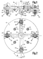
- the device referred to is basically constituted by a discoidal plate 10 on which some rotating units 20 equally spaced to each other are radially fixed in an adjustable manner at an adequate distance from its centre.
- the discoidal plate 10 is provided at its lower part with four radial guide grooves 11 having a "T" shaped cross-section, in which associated supports 21 are slidably engaged, on which respective rolls 22 of cylindric shape are applied and are arranged with their axis parallelly to said radial guide grooves 11, namely radially to the same plate.
- Said rolls 22 being also provided on their cylindric surface with a plurality of points constituted by respective sharpened elements 221 having high hardness and mechanical strength.
- said supports 21 are constituted by associated substantially parallelepiped blocks at whose upper part two flanges 211 are laterally projected therefrom, which are adapted to engage the longitudinal hollows 111 provided on the inner sides of said radial guide grooves 11 and inside which a cavity 212 is provided, which passes therethrough orthogonally to said radial Guide grooves and extends for the entire portion thereof being projected from said discoidal plate 10, thus providing two plates 213 for supporting said rolls 22.
- Respective holes are provided near the free ends of said plates 213 and centrally thereto, in which holes a cylindric shaft 214 is engaged, which is arranged with its axis parallel to the axis of the correspondent radial guide groove 11 on which said support 21 is fitted and an associated roll 22 is applied to said cylindric shaft 214, which therefore can freely rotate thereon.
- a stud bolt 23 extends orthogonally outwards on the upper part of each support 21 and enters respective radial cavities 112 provided on the upper part of said radial guide grooves 11 and extended for an adequate portion thereof, coaxially thereto, from the outer peripheral edge of the discoidal plate 10, and said stud bolt 23 is projected from said discoidal plate 10 with a suitable portion engaged by an associated nut 231.
- Said rotating units 20, described above in detail thus are radially slidable along the associated radial guide grooves 11 and can be fixed at the suitable desired position thereof by tightening the nuts 231 on the respective stud bolts 23.
- said discoidal plate 10 is removably fixed to an associated rotating support 30 by means of adequate fixing means provided on this support.
- said rotating support 30 is illustrated by a thin line and by way of example it is composed of a discoidal flange 31 extended from a shaft 32 and provided with stud bolts 33 entering correspondent holes provided on said discoidal plate 10 and engaged by associated nuts 34, adapted to permit the connection of said discoidal plate 10 to said discoidal flange 31.
- said rotating support 30 may have a different shape depending on the kind of machine which, as explained hereinafter, could be employed for performing the bushhammering operation.
- the unit constituting the device referred to is laid on the surface of the part to be worked, so that it presses on this part with an adequate pressure, then the rotating support 30 connected thereto is put in rotation while imparting at the same time a relative shifting between said device and the part to be worked.
- sharpened elements 221 which come into contact with the surface to be worked, due to their superficial hardness and the relevant limited resistance of penetration on the material being worked and to the pressure imparted thereto, penetrate fairly therein.
- the discoidal plate 10 is provided centrally with a through hole 4 which then is connected to the hole 35 which can be provided on the shaft 32 and an adequate fluid such i.e. water or also air may be directed through the so resulting conduit toward the surface being worked, thus such fluid being adapted to perform particular functions which are helpful for the same working operation.
- an adequate fluid such i.e. water or also air may be directed through the so resulting conduit toward the surface being worked, thus such fluid being adapted to perform particular functions which are helpful for the same working operation.
- the device referred to comprises four rotating units 20, but, obviously, it is well understood that such number may vary anyhow.
- a most reduced and for some aspects more rational arrangement thereof could be i.e. that composed solely of three rotating units 20, always disposed equally spaced to each other.
- said rotating units are illustrated all positioned at the same distance from the centre of the discoidal plate 10, but, clearly, they may also be disposed at different distances.
- the described device can be applied also to various kinds of machines which normally are employed for effecting other working operations.
- the working speed namely the surface treated in the time unit is quite greater than that which can be normally obtained with the known and normally utilized appliances.
- said sharpened elements 221 may have different shape and more precisely pyramidal or conic shape, and may be made integrally with the same roll 22 from which they are extended and in such case, clearly, they are made of the same material thereof or, more conveniently, may be achieved singly and separately by employing materials which are more suitable than those which form the roll 22, such as an appropriate hard material and, thereafter, they can be applied to and irremovably fixed with per se known means and systems on the same roll 22.
- sharpened elements 221 can be disposed on the cylindrical surface of said roll 22 along circumferential lines which are equally spaced and parallel to each other or, more advantageously, along helical lines.
- a remarkably effective particular arrangement thereof is that illustrated by way of example by the fig. 1 and 2, wherein said sharpened elements 221 are disposed along two groups of helicoidal lines equally spaced to each other, a first group of helicoids being spaced of an angle of 30° from the axis of the roll 20, and thus, the other group being spaced of an angle of 60° therefrom.
- the arrangement of the sharpened elements 221 may change anyhow as well as their shape, sizes and reciprocal distances and the sizes and shape of the rolls 22 may change too.
- the shape of the rolls 22 may be that cylindric as illustrated by way of example by the fig. 1 and 2 to which reference is made, or also a frusto-conical shape with the vertex thereof turned preferably inward, that is toward the rotation axis of the discoidal plate 10, or turned outward.
- said rolls may be connected also at determinate positions thereto.
Landscapes
- Engineering & Computer Science (AREA)
- Mining & Mineral Resources (AREA)
- Mechanical Engineering (AREA)
- Finish Polishing, Edge Sharpening, And Grinding By Specific Grinding Devices (AREA)
- Hinges (AREA)
- Closing And Opening Devices For Wings, And Checks For Wings (AREA)
- Superstructure Of Vehicle (AREA)
- Insulators (AREA)
- Prostheses (AREA)
- Shaping Metal By Deep-Drawing, Or The Like (AREA)
- Fish Paste Products (AREA)
- Crushing And Grinding (AREA)
Applications Claiming Priority (2)
| Application Number | Priority Date | Filing Date | Title |
|---|---|---|---|
| IT4579489 | 1989-11-17 | ||
| IT04579489A IT1236207B (it) | 1989-11-17 | 1989-11-17 | Sistema di bocciardatura e dispositivo per realizzare tale sistema |
Publications (2)
| Publication Number | Publication Date |
|---|---|
| EP0429893A1 EP0429893A1 (en) | 1991-06-05 |
| EP0429893B1 true EP0429893B1 (en) | 1996-01-31 |
Family
ID=11258174
Family Applications (1)
| Application Number | Title | Priority Date | Filing Date |
|---|---|---|---|
| EP90121172A Expired - Lifetime EP0429893B1 (en) | 1989-11-17 | 1990-11-06 | Bushhammering device |
Country Status (6)
| Country | Link |
|---|---|
| EP (1) | EP0429893B1 (it) |
| AT (1) | ATE133603T1 (it) |
| DE (1) | DE69025138T2 (it) |
| ES (1) | ES2027633T3 (it) |
| GR (1) | GR3019788T3 (it) |
| IT (1) | IT1236207B (it) |
Families Citing this family (5)
| Publication number | Priority date | Publication date | Assignee | Title |
|---|---|---|---|---|
| ES1020104Y (es) * | 1992-02-11 | 1993-07-16 | Moya Milian Concepcion | Aparato perfeccionado para desbastar superficies de piezas de piedra o de materiales similares. |
| ATE149909T1 (de) * | 1992-09-18 | 1997-03-15 | Lupato Antonio Er S R L | Handgeführte scharriervorrichtung mit rotierenden werkzeugen |
| ES2312269B1 (es) * | 2006-12-12 | 2009-12-18 | Digafer, S.A. | Cabezal de abujardar rotativo. |
| CN102729147A (zh) * | 2012-07-05 | 2012-10-17 | 厦门台颖金刚石制品有限公司 | 一种荔枝面辊轮组件及荔枝面磨头 |
| CN114434662B (zh) * | 2021-12-22 | 2025-03-04 | 中铁四局集团有限公司 | 离心摆臂式铁路箱梁锚穴凿毛器 |
Family Cites Families (6)
| Publication number | Priority date | Publication date | Assignee | Title |
|---|---|---|---|---|
| US1581699A (en) * | 1925-12-17 | 1926-04-20 | Ingersoll Rand Co | Surfacing machine |
| FR670862A (fr) * | 1929-03-06 | 1929-12-05 | Perfectionnements aux bouchardes pneumatiques ou électriques pour le travail de la pierre, du marbre, granit, grès | |
| US2244617A (en) * | 1939-01-14 | 1941-06-03 | Nat Tool Company | Roller bit |
| US3221619A (en) * | 1960-09-02 | 1965-12-07 | Arnel T Erickson | Rotating roller machine |
| US4405177A (en) * | 1981-04-17 | 1983-09-20 | Y K Trading Kabushiki Kaisha | Apparatus for finishing surfaces |
| DE8412179U1 (de) * | 1984-04-18 | 1984-09-20 | Dynapac Maskin AB, 17122 Solna | Rotationswerkzeug nach art eines schneidkopfes oder fraeskopfes |
-
1989
- 1989-11-17 IT IT04579489A patent/IT1236207B/it active IP Right Grant
-
1990
- 1990-11-06 EP EP90121172A patent/EP0429893B1/en not_active Expired - Lifetime
- 1990-11-06 ES ES90121172T patent/ES2027633T3/es not_active Expired - Lifetime
- 1990-11-06 DE DE69025138T patent/DE69025138T2/de not_active Expired - Fee Related
- 1990-11-06 AT AT90121172T patent/ATE133603T1/de not_active IP Right Cessation
-
1996
- 1996-04-29 GR GR960401168T patent/GR3019788T3/el unknown
Also Published As
| Publication number | Publication date |
|---|---|
| ES2027633T1 (es) | 1992-06-16 |
| EP0429893A1 (en) | 1991-06-05 |
| IT8945794A0 (it) | 1989-11-17 |
| DE69025138T2 (de) | 1996-12-12 |
| IT1236207B (it) | 1993-01-19 |
| IT8945794A1 (it) | 1991-05-17 |
| GR3019788T3 (en) | 1996-07-31 |
| ES2027633T3 (es) | 1996-04-16 |
| ATE133603T1 (de) | 1996-02-15 |
| DE69025138D1 (de) | 1996-03-14 |
Similar Documents
| Publication | Publication Date | Title |
|---|---|---|
| JP4806144B2 (ja) | 分割ブレードに隣接して突起部を有するメーソンリーブロック分割装置 | |
| US6561786B2 (en) | Apparatus for roughing surfaces of concrete casted blocks | |
| EP0429893B1 (en) | Bushhammering device | |
| IE43998B1 (en) | Rotary scraping or abrading tool | |
| US3678532A (en) | Rotating disc scraper | |
| US2085202A (en) | Brush | |
| US3695722A (en) | Apparatus for treating or digging into surfaces and cutting members for this apparatus | |
| US2242024A (en) | Machine for removing scale from rods | |
| WO2017013555A1 (en) | Adaptive plate for a polishing machine with improved distribution of the working pressure | |
| CN100339197C (zh) | 实木表层自然纹理生产工艺及装置 | |
| US2058731A (en) | Granite cutting machine | |
| AU734613B2 (en) | Apparatus for the production of stone spheres | |
| ES2248698T3 (es) | Herramienta para el corte y/o igualacion de superficies. | |
| DE500775C (de) | Anschleifen ebener oder auch konkaver Flaechen an Werkstuecken beliebiger Form der keramischen Industrie, der Natur- und Kunststein-Industrie, der Glas- und Metallindustrie u. dgl. | |
| US798587A (en) | Stone-rubbing machine. | |
| KR102759037B1 (ko) | 판석 가공방법 | |
| US3086509A (en) | Machine for cutting vitrified clay pipe | |
| RU2224650C1 (ru) | Способ утилизации изношенных автопокрышек и других резино-технических изделий и устройство для его реализации | |
| WO1998013173A1 (en) | Treating stones to simulate ageing | |
| US1878415A (en) | Tool for cutting stone | |
| US466161A (en) | Apparatus for tooling marble or other material | |
| US1298882A (en) | Imitation-graining tool. | |
| CN2736105Y (zh) | 手持凿毛机 | |
| EP1790433A1 (en) | Smoothing machine for wooden articles | |
| US97554A (en) | Improvement in machinery tor preparing wqoden blocks for pavement |
Legal Events
| Date | Code | Title | Description |
|---|---|---|---|
| PUAI | Public reference made under article 153(3) epc to a published international application that has entered the european phase |
Free format text: ORIGINAL CODE: 0009012 |
|
| AK | Designated contracting states |
Kind code of ref document: A1 Designated state(s): AT BE CH DE ES FR GB GR IT LI NL SE |
|
| 17P | Request for examination filed |
Effective date: 19910914 |
|
| 17Q | First examination report despatched |
Effective date: 19930408 |
|
| GRAA | (expected) grant |
Free format text: ORIGINAL CODE: 0009210 |
|
| AK | Designated contracting states |
Kind code of ref document: B1 Designated state(s): AT BE CH DE ES FR GB GR IT LI NL SE |
|
| REF | Corresponds to: |
Ref document number: 133603 Country of ref document: AT Date of ref document: 19960215 Kind code of ref document: T |
|
| REF | Corresponds to: |
Ref document number: 69025138 Country of ref document: DE Date of ref document: 19960314 |
|
| RAP2 | Party data changed (patent owner data changed or rights of a patent transferred) |
Owner name: LUPATO ANTONIO ER. S.R.L. |
|
| ITF | It: translation for a ep patent filed | ||
| REG | Reference to a national code |
Ref country code: CH Ref legal event code: NV Representative=s name: ISLER & PEDRAZZINI AG PATENTANWAELTE |
|
| REG | Reference to a national code |
Ref country code: ES Ref legal event code: FG2A Ref document number: 2027633 Country of ref document: ES Kind code of ref document: T3 |
|
| ET | Fr: translation filed | ||
| REG | Reference to a national code |
Ref country code: GR Ref legal event code: FG4A Free format text: 3019788 |
|
| PGFP | Annual fee paid to national office [announced via postgrant information from national office to epo] |
Ref country code: SE Payment date: 19961104 Year of fee payment: 7 |
|
| PGFP | Annual fee paid to national office [announced via postgrant information from national office to epo] |
Ref country code: NL Payment date: 19961130 Year of fee payment: 7 |
|
| PLBE | No opposition filed within time limit |
Free format text: ORIGINAL CODE: 0009261 |
|
| STAA | Information on the status of an ep patent application or granted ep patent |
Free format text: STATUS: NO OPPOSITION FILED WITHIN TIME LIMIT |
|
| 26N | No opposition filed | ||
| PGFP | Annual fee paid to national office [announced via postgrant information from national office to epo] |
Ref country code: CH Payment date: 19971103 Year of fee payment: 8 |
|
| PG25 | Lapsed in a contracting state [announced via postgrant information from national office to epo] |
Ref country code: SE Free format text: LAPSE BECAUSE OF NON-PAYMENT OF DUE FEES Effective date: 19971107 |
|
| PG25 | Lapsed in a contracting state [announced via postgrant information from national office to epo] |
Ref country code: NL Free format text: LAPSE BECAUSE OF NON-PAYMENT OF DUE FEES Effective date: 19980601 |
|
| EUG | Se: european patent has lapsed |
Ref document number: 90121172.2 |
|
| NLV4 | Nl: lapsed or anulled due to non-payment of the annual fee |
Effective date: 19980601 |
|
| PGFP | Annual fee paid to national office [announced via postgrant information from national office to epo] |
Ref country code: GB Payment date: 19981104 Year of fee payment: 9 |
|
| PGFP | Annual fee paid to national office [announced via postgrant information from national office to epo] |
Ref country code: FR Payment date: 19981105 Year of fee payment: 9 |
|
| PGFP | Annual fee paid to national office [announced via postgrant information from national office to epo] |
Ref country code: BE Payment date: 19981106 Year of fee payment: 9 |
|
| PGFP | Annual fee paid to national office [announced via postgrant information from national office to epo] |
Ref country code: GR Payment date: 19981111 Year of fee payment: 9 |
|
| PGFP | Annual fee paid to national office [announced via postgrant information from national office to epo] |
Ref country code: AT Payment date: 19981116 Year of fee payment: 9 |
|
| PG25 | Lapsed in a contracting state [announced via postgrant information from national office to epo] |
Ref country code: LI Free format text: LAPSE BECAUSE OF NON-PAYMENT OF DUE FEES Effective date: 19981130 Ref country code: CH Free format text: LAPSE BECAUSE OF NON-PAYMENT OF DUE FEES Effective date: 19981130 |
|
| REG | Reference to a national code |
Ref country code: CH Ref legal event code: PL |
|
| PG25 | Lapsed in a contracting state [announced via postgrant information from national office to epo] |
Ref country code: GB Free format text: LAPSE BECAUSE OF NON-PAYMENT OF DUE FEES Effective date: 19991106 Ref country code: AT Free format text: LAPSE BECAUSE OF NON-PAYMENT OF DUE FEES Effective date: 19991106 |
|
| PG25 | Lapsed in a contracting state [announced via postgrant information from national office to epo] |
Ref country code: GR Free format text: LAPSE BECAUSE OF NON-PAYMENT OF DUE FEES Effective date: 19991130 Ref country code: BE Free format text: LAPSE BECAUSE OF NON-PAYMENT OF DUE FEES Effective date: 19991130 |
|
| BERE | Be: lapsed |
Owner name: LUPATO ANTONIO ER. S.R.L. Effective date: 19991130 |
|
| GBPC | Gb: european patent ceased through non-payment of renewal fee |
Effective date: 19991106 |
|
| PG25 | Lapsed in a contracting state [announced via postgrant information from national office to epo] |
Ref country code: FR Free format text: LAPSE BECAUSE OF NON-PAYMENT OF DUE FEES Effective date: 20000731 |
|
| REG | Reference to a national code |
Ref country code: FR Ref legal event code: ST |
|
| PG25 | Lapsed in a contracting state [announced via postgrant information from national office to epo] |
Ref country code: IT Free format text: LAPSE BECAUSE OF NON-PAYMENT OF DUE FEES;WARNING: LAPSES OF ITALIAN PATENTS WITH EFFECTIVE DATE BEFORE 2007 MAY HAVE OCCURRED AT ANY TIME BEFORE 2007. THE CORRECT EFFECTIVE DATE MAY BE DIFFERENT FROM THE ONE RECORDED. Effective date: 20051106 |
|
| PGFP | Annual fee paid to national office [announced via postgrant information from national office to epo] |
Ref country code: ES Payment date: 20070531 Year of fee payment: 17 |
|
| PGFP | Annual fee paid to national office [announced via postgrant information from national office to epo] |
Ref country code: DE Payment date: 20070601 Year of fee payment: 17 |
|
| PG25 | Lapsed in a contracting state [announced via postgrant information from national office to epo] |
Ref country code: DE Free format text: LAPSE BECAUSE OF NON-PAYMENT OF DUE FEES Effective date: 20080603 |
|
| REG | Reference to a national code |
Ref country code: ES Ref legal event code: FD2A Effective date: 20071107 |
|
| PG25 | Lapsed in a contracting state [announced via postgrant information from national office to epo] |
Ref country code: ES Free format text: LAPSE BECAUSE OF NON-PAYMENT OF DUE FEES Effective date: 20071107 |