EP0429900A2 - Méthode de fabrication de soupapes creuses pour moteurs à pistons - Google Patents
Méthode de fabrication de soupapes creuses pour moteurs à pistons Download PDFInfo
- Publication number
- EP0429900A2 EP0429900A2 EP90121253A EP90121253A EP0429900A2 EP 0429900 A2 EP0429900 A2 EP 0429900A2 EP 90121253 A EP90121253 A EP 90121253A EP 90121253 A EP90121253 A EP 90121253A EP 0429900 A2 EP0429900 A2 EP 0429900A2
- Authority
- EP
- European Patent Office
- Prior art keywords
- welding
- bore
- filler
- build
- carried out
- Prior art date
- Legal status (The legal status is an assumption and is not a legal conclusion. Google has not performed a legal analysis and makes no representation as to the accuracy of the status listed.)
- Granted
Links
Images



Classifications
-
- B—PERFORMING OPERATIONS; TRANSPORTING
- B23—MACHINE TOOLS; METAL-WORKING NOT OTHERWISE PROVIDED FOR
- B23K—SOLDERING OR UNSOLDERING; WELDING; CLADDING OR PLATING BY SOLDERING OR WELDING; CUTTING BY APPLYING HEAT LOCALLY, e.g. FLAME CUTTING; WORKING BY LASER BEAM
- B23K26/00—Working by laser beam, e.g. welding, cutting or boring
- B23K26/20—Bonding
- B23K26/206—Laser sealing
-
- B—PERFORMING OPERATIONS; TRANSPORTING
- B23—MACHINE TOOLS; METAL-WORKING NOT OTHERWISE PROVIDED FOR
- B23K—SOLDERING OR UNSOLDERING; WELDING; CLADDING OR PLATING BY SOLDERING OR WELDING; CUTTING BY APPLYING HEAT LOCALLY, e.g. FLAME CUTTING; WORKING BY LASER BEAM
- B23K10/00—Welding or cutting by means of a plasma
- B23K10/02—Plasma welding
-
- B—PERFORMING OPERATIONS; TRANSPORTING
- B23—MACHINE TOOLS; METAL-WORKING NOT OTHERWISE PROVIDED FOR
- B23K—SOLDERING OR UNSOLDERING; WELDING; CLADDING OR PLATING BY SOLDERING OR WELDING; CUTTING BY APPLYING HEAT LOCALLY, e.g. FLAME CUTTING; WORKING BY LASER BEAM
- B23K15/00—Electron-beam welding or cutting
- B23K15/0006—Electron-beam welding or cutting specially adapted for particular articles or work
-
- B—PERFORMING OPERATIONS; TRANSPORTING
- B23—MACHINE TOOLS; METAL-WORKING NOT OTHERWISE PROVIDED FOR
- B23K—SOLDERING OR UNSOLDERING; WELDING; CLADDING OR PLATING BY SOLDERING OR WELDING; CUTTING BY APPLYING HEAT LOCALLY, e.g. FLAME CUTTING; WORKING BY LASER BEAM
- B23K15/00—Electron-beam welding or cutting
- B23K15/0046—Welding
- B23K15/0086—Welding welding for purposes other than joining, e.g. build-up welding
-
- B—PERFORMING OPERATIONS; TRANSPORTING
- B23—MACHINE TOOLS; METAL-WORKING NOT OTHERWISE PROVIDED FOR
- B23K—SOLDERING OR UNSOLDERING; WELDING; CLADDING OR PLATING BY SOLDERING OR WELDING; CUTTING BY APPLYING HEAT LOCALLY, e.g. FLAME CUTTING; WORKING BY LASER BEAM
- B23K26/00—Working by laser beam, e.g. welding, cutting or boring
- B23K26/20—Bonding
- B23K26/32—Bonding taking account of the properties of the material involved
-
- B—PERFORMING OPERATIONS; TRANSPORTING
- B23—MACHINE TOOLS; METAL-WORKING NOT OTHERWISE PROVIDED FOR
- B23K—SOLDERING OR UNSOLDERING; WELDING; CLADDING OR PLATING BY SOLDERING OR WELDING; CUTTING BY APPLYING HEAT LOCALLY, e.g. FLAME CUTTING; WORKING BY LASER BEAM
- B23K26/00—Working by laser beam, e.g. welding, cutting or boring
- B23K26/34—Laser welding for purposes other than joining
-
- B—PERFORMING OPERATIONS; TRANSPORTING
- B23—MACHINE TOOLS; METAL-WORKING NOT OTHERWISE PROVIDED FOR
- B23K—SOLDERING OR UNSOLDERING; WELDING; CLADDING OR PLATING BY SOLDERING OR WELDING; CUTTING BY APPLYING HEAT LOCALLY, e.g. FLAME CUTTING; WORKING BY LASER BEAM
- B23K26/00—Working by laser beam, e.g. welding, cutting or boring
- B23K26/34—Laser welding for purposes other than joining
- B23K26/342—Build-up welding
-
- B—PERFORMING OPERATIONS; TRANSPORTING
- B23—MACHINE TOOLS; METAL-WORKING NOT OTHERWISE PROVIDED FOR
- B23K—SOLDERING OR UNSOLDERING; WELDING; CLADDING OR PLATING BY SOLDERING OR WELDING; CUTTING BY APPLYING HEAT LOCALLY, e.g. FLAME CUTTING; WORKING BY LASER BEAM
- B23K35/00—Rods, electrodes, materials, or media, for use in soldering, welding, or cutting
- B23K35/02—Rods, electrodes, materials, or media, for use in soldering, welding, or cutting characterised by mechanical features, e.g. shape
- B23K35/0222—Rods, electrodes, materials, or media, for use in soldering, welding, or cutting characterised by mechanical features, e.g. shape for use in soldering or brazing
- B23K35/0244—Powders, particles or spheres; Preforms made therefrom
-
- B—PERFORMING OPERATIONS; TRANSPORTING
- B23—MACHINE TOOLS; METAL-WORKING NOT OTHERWISE PROVIDED FOR
- B23K—SOLDERING OR UNSOLDERING; WELDING; CLADDING OR PLATING BY SOLDERING OR WELDING; CUTTING BY APPLYING HEAT LOCALLY, e.g. FLAME CUTTING; WORKING BY LASER BEAM
- B23K35/00—Rods, electrodes, materials, or media, for use in soldering, welding, or cutting
- B23K35/02—Rods, electrodes, materials, or media, for use in soldering, welding, or cutting characterised by mechanical features, e.g. shape
- B23K35/0255—Rods, electrodes, materials, or media, for use in soldering, welding, or cutting characterised by mechanical features, e.g. shape for use in welding
-
- B—PERFORMING OPERATIONS; TRANSPORTING
- B23—MACHINE TOOLS; METAL-WORKING NOT OTHERWISE PROVIDED FOR
- B23K—SOLDERING OR UNSOLDERING; WELDING; CLADDING OR PLATING BY SOLDERING OR WELDING; CUTTING BY APPLYING HEAT LOCALLY, e.g. FLAME CUTTING; WORKING BY LASER BEAM
- B23K35/00—Rods, electrodes, materials, or media, for use in soldering, welding, or cutting
- B23K35/02—Rods, electrodes, materials, or media, for use in soldering, welding, or cutting characterised by mechanical features, e.g. shape
- B23K35/0255—Rods, electrodes, materials, or media, for use in soldering, welding, or cutting characterised by mechanical features, e.g. shape for use in welding
- B23K35/0261—Rods, electrodes or wires
-
- B—PERFORMING OPERATIONS; TRANSPORTING
- B23—MACHINE TOOLS; METAL-WORKING NOT OTHERWISE PROVIDED FOR
- B23K—SOLDERING OR UNSOLDERING; WELDING; CLADDING OR PLATING BY SOLDERING OR WELDING; CUTTING BY APPLYING HEAT LOCALLY, e.g. FLAME CUTTING; WORKING BY LASER BEAM
- B23K35/00—Rods, electrodes, materials, or media, for use in soldering, welding, or cutting
- B23K35/22—Rods, electrodes, materials, or media, for use in soldering, welding, or cutting characterised by the composition or nature of the material
- B23K35/24—Selection of soldering or welding materials proper
- B23K35/30—Selection of soldering or welding materials proper with the principal constituent melting at less than 1550°C
- B23K35/3053—Fe as the principal constituent
-
- B—PERFORMING OPERATIONS; TRANSPORTING
- B23—MACHINE TOOLS; METAL-WORKING NOT OTHERWISE PROVIDED FOR
- B23K—SOLDERING OR UNSOLDERING; WELDING; CLADDING OR PLATING BY SOLDERING OR WELDING; CUTTING BY APPLYING HEAT LOCALLY, e.g. FLAME CUTTING; WORKING BY LASER BEAM
- B23K35/00—Rods, electrodes, materials, or media, for use in soldering, welding, or cutting
- B23K35/22—Rods, electrodes, materials, or media, for use in soldering, welding, or cutting characterised by the composition or nature of the material
- B23K35/24—Selection of soldering or welding materials proper
- B23K35/32—Selection of soldering or welding materials proper with the principal constituent melting at more than 1550°C
- B23K35/322—Selection of soldering or welding materials proper with the principal constituent melting at more than 1550°C a Pt-group metal as principal constituent
-
- B—PERFORMING OPERATIONS; TRANSPORTING
- B23—MACHINE TOOLS; METAL-WORKING NOT OTHERWISE PROVIDED FOR
- B23K—SOLDERING OR UNSOLDERING; WELDING; CLADDING OR PLATING BY SOLDERING OR WELDING; CUTTING BY APPLYING HEAT LOCALLY, e.g. FLAME CUTTING; WORKING BY LASER BEAM
- B23K5/00—Gas flame welding
- B23K5/18—Gas flame welding for purposes other than joining parts, e.g. built-up welding
-
- B—PERFORMING OPERATIONS; TRANSPORTING
- B23—MACHINE TOOLS; METAL-WORKING NOT OTHERWISE PROVIDED FOR
- B23K—SOLDERING OR UNSOLDERING; WELDING; CLADDING OR PLATING BY SOLDERING OR WELDING; CUTTING BY APPLYING HEAT LOCALLY, e.g. FLAME CUTTING; WORKING BY LASER BEAM
- B23K9/00—Arc welding or cutting
- B23K9/0026—Arc welding or cutting specially adapted for particular articles or work
-
- B—PERFORMING OPERATIONS; TRANSPORTING
- B23—MACHINE TOOLS; METAL-WORKING NOT OTHERWISE PROVIDED FOR
- B23K—SOLDERING OR UNSOLDERING; WELDING; CLADDING OR PLATING BY SOLDERING OR WELDING; CUTTING BY APPLYING HEAT LOCALLY, e.g. FLAME CUTTING; WORKING BY LASER BEAM
- B23K9/00—Arc welding or cutting
- B23K9/04—Welding for other purposes than joining, e.g. built-up welding
-
- B—PERFORMING OPERATIONS; TRANSPORTING
- B23—MACHINE TOOLS; METAL-WORKING NOT OTHERWISE PROVIDED FOR
- B23P—METAL-WORKING NOT OTHERWISE PROVIDED FOR; COMBINED OPERATIONS; UNIVERSAL MACHINE TOOLS
- B23P15/00—Making specific metal objects by operations not covered by a single other subclass or a group in this subclass
- B23P15/001—Making specific metal objects by operations not covered by a single other subclass or a group in this subclass valves or valve housings
- B23P15/002—Making specific metal objects by operations not covered by a single other subclass or a group in this subclass valves or valve housings poppet valves
-
- F—MECHANICAL ENGINEERING; LIGHTING; HEATING; WEAPONS; BLASTING
- F01—MACHINES OR ENGINES IN GENERAL; ENGINE PLANTS IN GENERAL; STEAM ENGINES
- F01L—CYCLICALLY OPERATING VALVES FOR MACHINES OR ENGINES
- F01L3/00—Lift-valve, i.e. cut-off apparatus with closure members having at least a component of their opening and closing motion perpendicular to the closing faces; Parts or accessories thereof
- F01L3/12—Cooling of valves
- F01L3/14—Cooling of valves by means of a liquid or solid coolant, e.g. sodium, in a closed chamber in a valve
-
- B—PERFORMING OPERATIONS; TRANSPORTING
- B23—MACHINE TOOLS; METAL-WORKING NOT OTHERWISE PROVIDED FOR
- B23K—SOLDERING OR UNSOLDERING; WELDING; CLADDING OR PLATING BY SOLDERING OR WELDING; CUTTING BY APPLYING HEAT LOCALLY, e.g. FLAME CUTTING; WORKING BY LASER BEAM
- B23K2101/00—Articles made by soldering, welding or cutting
- B23K2101/003—Pistons
-
- B—PERFORMING OPERATIONS; TRANSPORTING
- B23—MACHINE TOOLS; METAL-WORKING NOT OTHERWISE PROVIDED FOR
- B23K—SOLDERING OR UNSOLDERING; WELDING; CLADDING OR PLATING BY SOLDERING OR WELDING; CUTTING BY APPLYING HEAT LOCALLY, e.g. FLAME CUTTING; WORKING BY LASER BEAM
- B23K2101/00—Articles made by soldering, welding or cutting
- B23K2101/006—Vehicles
-
- B—PERFORMING OPERATIONS; TRANSPORTING
- B23—MACHINE TOOLS; METAL-WORKING NOT OTHERWISE PROVIDED FOR
- B23K—SOLDERING OR UNSOLDERING; WELDING; CLADDING OR PLATING BY SOLDERING OR WELDING; CUTTING BY APPLYING HEAT LOCALLY, e.g. FLAME CUTTING; WORKING BY LASER BEAM
- B23K2103/00—Materials to be soldered, welded or cut
- B23K2103/50—Inorganic materials other than metals or composite materials
Definitions
- the invention relates to a method for producing hollow gas exchange valves for reciprocating piston machines according to the preamble of claim 1, as is known for example from DE-OS 23 61 712.
- sealing plugs themselves are also not very cheap, in particular because the high-quality and tough material for machining causes high tool costs.
- a precisely localizable weld for Sealed welding of the sealing plug also requires a very precise positioning device, so that only a very expensive welding device can be used for this, which also costs the method.
- the preferred welding methods in this context such as laser or electron beam welding, require a relatively complex and expensive testing technique for process and quality assurance. This elaborate test also costs the known method.
- the thin-walled circular blank for holding the welding melt which can also be produced only with material losses, can be produced from an inexpensive and easily machinable material in which the material waste is not significant in terms of cost. Due to the thin wall thickness and the low strength of this material, the tools used can be expected to have a long service life, so that hardly any costs are incurred in this regard.
- the coolable gas exchange valve for reciprocating piston machines shown in FIG. 1 has a valve plate 2 and a valve stem 3, the latter of which has a cavity 6 which is partially filled with a cooling medium 4, preferably sodium.
- a cooling medium 4 preferably sodium.
- the cavity formed as a bore 6 is closed on the plate side by a plug 8, the attachment of which is explained in more detail below.
- FIGS. 2 to 5 shows various essential phases in the manufacture of the gas exchange valve according to FIG. 1.
- the cavity within the valve stem is cleared by axial drilling from the plate side (FIG. 2).
- a quantity is defined in the finished and cleaned bore 6 dimensioned coolant compact 18 made of sodium, for example, care should be taken that the sodium comes into contact with air or the oxygen contained therein as little and / or only briefly.
- a further process step (FIG. 4), with the aid of a centering device 20, which is only indicated as an example, and a press ram 21, a small filler piece 7 is pressed into the bore opening to a defined depth, the press-in depth approximately corresponding to the thickness B of the subsequent sealing plug.
- This sealing plug 8 is attached in a further process step indicated in FIG. 5 by a build-up welding, the alloy material making up the sealing plug being added in a thermally highly resilient quality during welding by a consumable electrode or in the form of a blown-in powder.
- the sealing plug 8, which can thus be produced quickly, easily and in a material-saving manner, is shown in greatly enlarged form in FIG. 6. It can be seen there that the filler piece 7 which is initially pressed into the bore 6 to a defined depth has a very small wall thickness (dimension a). This filler made of an inexpensive sheet steel merely has the function of holding the weld melt of the build-up weld in the bore 6 at the end during the welding.
- the filler 7 is also melted to a very great extent, as is the intended edge zone of the bore 6.
- the welding torch 11 for example, so much material is supplied via the electrode 12 until the upper edge of the weld pool is approximately flush with the free plate side 9.
- TIG, MIG or plasma powder welding processes which are assumed to be known here are suitable as welding processes for carrying out such a build-up welding.
- the filler pieces 7 can be punched out of sheet metal, preferably of a low-alloy steel, which can be carried out in a rational manner with long tool lives due to the low material strength of this material.
- the filler 7 is preferably designed as a flat board, as most of the illustrated embodiments show.
- steel other materials, in particular copper, are also conceivable, which favors the heat transfer from the cooling medium in the alloyed sealing plugs, which are attached by means of the build-up welding process.
- the copper which dissipates the welding heat better into the valve disk, is more resistant to burning or melting through than a steel plate.
- other materials such as brass or aluminum are also conceivable, even the use of plastic may be suitable additives should not be completely disregarded.
- the filler piece 7 is held non-positively in the region of the bore opening by a press fit.
- a more or less large oversize of the diameter of the filler 7 compared to the diameter of the bore 6 is less catastrophic, so that rough tolerances can be easily accepted.
- the pressing force and the stability of the valve plate 2 will in any case be sufficient to allow the filler 7 to be inserted in a defined position even in the case of a large oversize, without the valve plate underneath being visibly deformed.
- the press-in depth can be exactly predetermined.
- a cylindrical countersink 22 is attached to the bore 6 on the plate side , through which a shoulder 13 is created, on which the filler 7 'can lie in a position-defined and form-fitting manner. It can be both a press fit and a play fit of the filler 7 'within the countersink 22. Otherwise, the exemplary embodiment according to FIG. 7 largely corresponds to that according to FIG. 6.
- the plate-side end of the bore 6 is drilled out to a larger diameter (bore 23) and thereby a conical transition (bore shoulder 14) to the valve stem bore 6 is created.
- the filler piece 7 "is loosely inserted or pressed in. In any case, it lies in a form-fitting manner on the edge of the bore shoulder 14 which is adjacent to the free plate side 9
- a reduction in weight can be achieved by boring.
- this bored-out version also requires a larger filler piece 7 "and a larger diameter plug 8 '. Because of the greater heat input during build-up welding, the filler 7 ' would have to be dimensioned sufficiently thick in terms of wall so that it does not melt under the effect of this heat input.
- the filling piece is designed in the form of a truncated cone-shaped cap 15.
- a bore 23 ' is also provided, through which a conical bore shoulder 14' is also formed in the transition region to the bore 6.
- the cap 15 is inserted with its closed side 15 facing outward into the bore 23 ', so that the hollow conical open side 17 of the cap faces the inside of the valve stem bore.
- the filler formed as a cap 15 is not as easy to manufacture as a flat circuit board; moreover, when inserting the cap into the bore 23 ', care must be taken that it is inserted in the correct direction.
- the design according to FIG. 9 has the advantage that less material is required for the sealing plug 8 ", which results in a cost reduction in terms of the amount of material.
- the reduced use of materials also has weight advantages which have a favorable effect in engine operation Cooling area in the area towards the free side of the plate larger than with one flat filler design; finally, the wall thicknesses that are decisive for heat conduction are permissibly lower than in the other exemplary embodiments, at least in the area of the center of the bore, which also favors the heat transfer.
- the inventive closing of the cavity 5 'in the stem 3' of the gas exchange valve 1 ' is also possible at the free end of the valve stem, as shown in FIG. 10.
- the open end of the bore is also closed by a filler 7 holding the weld pool end and by a sealing plug 8 attached by means of a weld overlay.
- a machining finish must follow on the circumference and on the front.
- edge effect can be observed in the previously mentioned welding processes, in particular when smaller bores are to be welded closed.
- This edge effect manifests itself in the fact that the current wants to flow on the path of the least electrical resistance and is therefore concentrated in the edge region.
- the filler material is preferably built up on the protruding workpiece edge located in the current flow.
- Such an edge effect makes it difficult to weld overlay from the bottom of the opening covered with the sealing plug.
- Such processes are recommended for the build-up welding in which the workpiece is arranged outside of and electrically passive in relation to the welding energy flow melting the addition material and the valve material.
- the generalized selection criterion for suitable welding processes that is provided in this way allows targeted selection of suitable welding processes, for example laser welding or electron beam welding or even oxy-fuel welding. In the present case, these welding processes avoid disadvantageous edge effects.
- the welding is carried out by means of a laser beam 25 emerging from the laser head 24, the powdered filler material being metered into the welding point through a feed pipe 26 in accordance with the progress of the build-up welding.
- the valve 1 is slowly rotated and / or radially displaced with respect to the valve position shown as the welding progresses. In this way, from below, i. H. from the pressed-in filler 7 the plug is gradually built up or applied. Disturbing edge effects do not impair the orderly introduction of the welding melt from below.
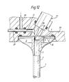
- Figure 12 shows a conceivable embodiment of a very similar arrangement, but here a beam gun 27 is provided as an energy source for the build-up welding to generate an electron beam 28, which is also focused in the area of the subsequent sealing plug.
- the gas exchange valve with the free plate side 9 is sealingly inserted into a housing 33, so that a vacuum chamber 32 is thus formed on the end face of the beam gun 27.
- This vacuum chamber is evacuated after inserting the gas exchange valve, whereupon the build-up welding can begin.
- the feed of the filler material is also provided in powder form. However, care must be taken that the vacuum is not impaired when the powder is supplied.
- the one shown in FIG Example is for this purpose by means of a metering piston 29 the metal powder kept ready in a horizontal cylindrical metering chamber slowly pushed out towards the vacuum chamber, where it trickles into the spot of the beam focus by gravity and is melted there.
- the valve must be displaced in the circumferential direction and / or radially in order to be able to reach all areas of the sealing plug through the focus, which is not indicated in the drawing, however.
- Certain beam displacements can also be carried out on the part of the beam gun 27 by means of corresponding beam deflections.
- the metering chamber 31 can be filled again from the inlet pipe 30 by pulling back the metering piston 29.
- An orderly filling of the stopper volume with high quality material is also possible by means of electron beam welding without annoying edge effects.
- a precisely coordinated quantity of powder 34 is previously filled into the opening which forms the subsequent sealing plug and is closed at the bottom by the filler 7; After the amount of powder 34 takes up more space than the melted sealing plug due to the lower bulk density compared to the density of the full cross section, the excess of the powder is secured by a ceramic ring 35 placed in a defined position on the free plate side 9.
- the powder is melted from above by the electron beam 28 oscillating and / or rotating over the amount of powder over a longer period of time, the melting front gradually passing through the entire powder bed and reaching the filler 7 and the side wall of the bore 6 and also melting it . As the melting increases, the powder slumps and the surface of the molten pool sinks with it so that the electron beam may have to be refocused accordingly.
- the build-up welding is carried out with an oxy-fuel welding torch 36 which generates a small welding flame 37, the application material being supplied in the form of a welding wire 38 via a guide tube 39.
- the welding wire of thermally highly resilient material quality can be stored on a large coil.
Landscapes
- Engineering & Computer Science (AREA)
- Mechanical Engineering (AREA)
- Physics & Mathematics (AREA)
- Optics & Photonics (AREA)
- Plasma & Fusion (AREA)
- General Engineering & Computer Science (AREA)
- Laser Beam Processing (AREA)
- Welding Or Cutting Using Electron Beams (AREA)
- Butt Welding And Welding Of Specific Article (AREA)
- Cylinder Crankcases Of Internal Combustion Engines (AREA)
- Valve Housings (AREA)
- Fluid-Driven Valves (AREA)
Applications Claiming Priority (4)
| Application Number | Priority Date | Filing Date | Title |
|---|---|---|---|
| DE3939348 | 1989-11-29 | ||
| DE3939348 | 1989-11-29 | ||
| DE4024084A DE4024084A1 (de) | 1989-11-29 | 1990-07-28 | Verfahren zum herstellen von hohlen gaswechselventilen fuer hubkolbenmaschinen |
| DE4024084 | 1990-07-28 |
Publications (3)
| Publication Number | Publication Date |
|---|---|
| EP0429900A2 true EP0429900A2 (fr) | 1991-06-05 |
| EP0429900A3 EP0429900A3 (en) | 1991-10-16 |
| EP0429900B1 EP0429900B1 (fr) | 1993-08-11 |
Family
ID=25887463
Family Applications (1)
| Application Number | Title | Priority Date | Filing Date |
|---|---|---|---|
| EP90121253A Expired - Lifetime EP0429900B1 (fr) | 1989-11-29 | 1990-11-07 | Méthode de fabrication de soupapes creuses pour moteurs à pistons |
Country Status (5)
| Country | Link |
|---|---|
| US (1) | US5126530A (fr) |
| EP (1) | EP0429900B1 (fr) |
| JP (1) | JPH0686009B2 (fr) |
| DE (2) | DE4024084A1 (fr) |
| ES (1) | ES2045718T3 (fr) |
Cited By (4)
| Publication number | Priority date | Publication date | Assignee | Title |
|---|---|---|---|---|
| CN102601507A (zh) * | 2012-03-22 | 2012-07-25 | 镇江维纳特气门有限公司 | 一种气门等离子堆焊焊接方法 |
| EP2541001A4 (fr) * | 2010-02-26 | 2013-10-16 | Mitsubishi Heavy Ind Ltd | Procédé de production de soupape de moteur remplie de sodium métallique |
| WO2015036257A1 (fr) * | 2013-09-16 | 2015-03-19 | Mahle International Gmbh | Soupape creuse, notamment pour moteur à combustion interne |
| CN105215570A (zh) * | 2014-06-24 | 2016-01-06 | 盐城环宇汽车零部件制造有限公司 | 一种平面密封新方法 |
Families Citing this family (19)
| Publication number | Priority date | Publication date | Assignee | Title |
|---|---|---|---|---|
| US5245155A (en) * | 1992-03-06 | 1993-09-14 | General Electric Company | Single point powder feed nozzle for use in laser welding |
| DE19803294A1 (de) * | 1998-01-29 | 1999-08-05 | Mwp Mahle J Wizemann Pleuco Gm | Einen Hohlraum aufweisendes Gaswechselventil |
| DE10296191D2 (de) * | 2001-12-27 | 2003-12-18 | Mahle Ventiltrieb Gmbh | Gaswechselventil eines Verbrennungsmotors mit einem hohlen Ventilteller |
| WO2003100223A1 (fr) * | 2002-05-28 | 2003-12-04 | Daimlerchrysler Ag | Procede de realisation d'une soupape integree a tige creuse pour moteur a piston alternatif |
| JP3925491B2 (ja) * | 2003-11-20 | 2007-06-06 | 株式会社デンソー | レーザ溶着方法、構造およびスロットルバルブ装置 |
| GB2418166A (en) * | 2004-09-15 | 2006-03-22 | Rolls Royce Plc | Component fabrication using electron beam deposition welding |
| BR102013021206A2 (pt) | 2012-12-11 | 2014-09-09 | Wärtsilä Schweiz AG | Válvula de troca de gás bem como método para fabricação de válvula de troca de gás |
| DE102013210897A1 (de) * | 2013-06-11 | 2014-12-11 | Mahle International Gmbh | Verfahren zur Herstellung eines gebauten Hohlventils einer Brennkraftmaschine |
| DE102013210899A1 (de) * | 2013-06-11 | 2014-12-11 | Mahle International Gmbh | Verfahren zur Herstellung eines gebauten Hohlventils |
| PL3073067T3 (pl) * | 2013-11-21 | 2019-09-30 | Nittan Valve Co., Ltd. | Sposób wytwarzania wydrążonego zaworu grzybkowego |
| KR101458189B1 (ko) * | 2014-01-02 | 2014-11-05 | 문명성 | 중공밸브 제조방법 |
| DE102014225618A1 (de) * | 2014-12-11 | 2016-06-16 | Mahle International Gmbh | Verfahren zur Herstellung eines Hohlventils |
| CN106077914B (zh) * | 2016-07-15 | 2019-07-09 | 南京国际船舶设备配件有限公司 | 一种船用低速机气阀盘底及其焊接工艺 |
| CN106563863A (zh) * | 2016-10-20 | 2017-04-19 | 重庆跃进机械厂有限公司 | 中速机气阀阀面mig堆焊方法 |
| CN108817716B (zh) * | 2018-09-18 | 2020-12-11 | 上海交通大学 | 一种适用于小规格孔内激光堆焊的送粉装置 |
| CN109202365B (zh) * | 2018-11-12 | 2020-08-18 | 湖北秦鸿新材料股份有限公司 | 一种磨煤机辊套的在线堆焊修复方法 |
| CN109434288A (zh) * | 2018-12-04 | 2019-03-08 | 上海交通大学 | 超快激光锥孔打孔装置及打孔工艺 |
| JP7325194B2 (ja) * | 2019-02-19 | 2023-08-14 | 三菱重工業株式会社 | 溶接物製造方法、溶接物製造システム及び溶接物 |
| CN110449737A (zh) * | 2019-08-19 | 2019-11-15 | 芜湖天弋能源科技有限公司 | 一种修复动力电池壳体和顶盖激光焊炸点的方法 |
Family Cites Families (31)
| Publication number | Priority date | Publication date | Assignee | Title |
|---|---|---|---|---|
| US1628911A (en) * | 1926-11-05 | 1927-05-17 | George R Rich | Electrically-welded valve tappet |
| GB471605A (en) * | 1935-08-17 | 1937-09-08 | Teves Kg Alfred | Improvements in or relating to hollow poppet valves |
| GB489384A (en) * | 1937-02-03 | 1938-07-26 | Harold Ernest Gresham | Improvements in mushroom valves for internal combustion engines |
| GB532184A (en) * | 1939-08-19 | 1941-01-20 | British Aero Components Ltd | Improvements in poppet valves and their manufacture |
| US2440461A (en) * | 1944-04-22 | 1948-04-27 | Eaton Mfg Co | Method of sealing the stem of hollow valves |
| FR917196A (fr) * | 1944-06-26 | 1946-12-27 | Thompson Prod Inc | Procédé de fabrication de soupapes creuses à soulèvement renfermant un agent de refroidissement tel que le sodium |
| DE903017C (de) * | 1951-01-31 | 1954-02-01 | Sueddeutsche Lab G M B H | Herstellung kleiner Kugeln aus hochschmelzbaren Materialien |
| US4831230B1 (en) * | 1957-06-27 | 1996-10-29 | Bankers Trust Company | Surface shaping and finishing apparatus and method |
| CA610681A (en) * | 1957-11-20 | 1960-12-13 | Carl Zeiss | Programmed particle irradiation accelerator |
| NL255532A (fr) * | 1959-09-04 | |||
| US3233599A (en) * | 1964-10-12 | 1966-02-08 | Bayerisches Leichtmetallwerk K | Valve, valve-manufacturing process and articles used in said process |
| FR1533755A (fr) * | 1966-08-16 | 1968-07-19 | Jeol Ltd | Dispositif pour le réglage du point de traitement dans un appareil à faisceau électrique ou analogue |
| DE1927613A1 (de) * | 1969-05-30 | 1970-12-03 | Essener Schweisselektroden Wer | Elektrisches Lichtbogenschweissverfahren |
| US3699334A (en) * | 1969-06-16 | 1972-10-17 | Kollsman Instr Corp | Apparatus using a beam of positive ions for controlled erosion of surfaces |
| DE1960331A1 (de) * | 1969-12-02 | 1971-06-03 | Porsche Kg | Kegelventil,insbesondere fuer Brennkraftmaschinen |
| US3644700A (en) * | 1969-12-15 | 1972-02-22 | Ibm | Method and apparatus for controlling an electron beam |
| US3699304A (en) * | 1969-12-15 | 1972-10-17 | Ibm | Electron beam deflection control method and apparatus |
| IT1046261B (it) * | 1973-07-11 | 1980-06-30 | Eaton Spa | Procedimento per la fabbricazione di valvole cave e valvole cosi ottenute per motori a combustione interna ed altre macchine in genere |
| US3894271A (en) * | 1973-08-31 | 1975-07-08 | Ibm | Method and apparatus for aligning electron beams |
| US3900736A (en) * | 1974-01-28 | 1975-08-19 | Ibm | Method and apparatus for positioning a beam of charged particles |
| US3956052A (en) * | 1974-02-11 | 1976-05-11 | International Business Machines Corporation | Recessed metallurgy for dielectric substrates |
| US4199689A (en) * | 1977-12-21 | 1980-04-22 | Tokyo Shibaura Denki Kabushiki Kaisha | Electron beam exposing method and electron beam apparatus |
| US4406046A (en) * | 1979-09-08 | 1983-09-27 | Mtu Motoren- Und Turbinen-Union Munchen, Gmbh | Process for the production of a sodium-filled valve |
| US4544442A (en) * | 1981-04-14 | 1985-10-01 | Kollmorgen Technologies Corporation | Process for the manufacture of substrates to interconnect electronic components |
| JPS57209786A (en) * | 1981-06-17 | 1982-12-23 | Hitachi Ltd | Electron beam machining device |
| US4425829A (en) * | 1981-09-17 | 1984-01-17 | International Business Machines Corporation | Punch apparatus |
| DE3243033A1 (de) * | 1982-11-22 | 1984-05-24 | Institut für Kerntechnik und Energiewandlung e.V., 7000 Stuttgart | Verfahren und anordnung zum bearbeiten eines werkstuecks mittels eines fokussierten elektronenstrahls |
| GB2144060B (en) * | 1983-07-28 | 1986-04-09 | Lucas Ind Plc | Electromagnetic valve assembly |
| US4555610A (en) * | 1983-09-13 | 1985-11-26 | Data Card Corporation | Laser machining system |
| US4821614A (en) * | 1986-03-10 | 1989-04-18 | International Business Machines Corporation | Programmable magnetic repulsion punching apparatus |
| US4789770A (en) * | 1987-07-15 | 1988-12-06 | Westinghouse Electric Corp. | Controlled depth laser drilling system |
-
1990
- 1990-07-28 DE DE4024084A patent/DE4024084A1/de active Granted
- 1990-11-07 EP EP90121253A patent/EP0429900B1/fr not_active Expired - Lifetime
- 1990-11-07 ES ES90121253T patent/ES2045718T3/es not_active Expired - Lifetime
- 1990-11-07 DE DE9090121253T patent/DE59002302D1/de not_active Expired - Fee Related
- 1990-11-22 JP JP2315710A patent/JPH0686009B2/ja not_active Expired - Fee Related
- 1990-11-29 US US07/619,517 patent/US5126530A/en not_active Expired - Fee Related
Cited By (4)
| Publication number | Priority date | Publication date | Assignee | Title |
|---|---|---|---|---|
| EP2541001A4 (fr) * | 2010-02-26 | 2013-10-16 | Mitsubishi Heavy Ind Ltd | Procédé de production de soupape de moteur remplie de sodium métallique |
| CN102601507A (zh) * | 2012-03-22 | 2012-07-25 | 镇江维纳特气门有限公司 | 一种气门等离子堆焊焊接方法 |
| WO2015036257A1 (fr) * | 2013-09-16 | 2015-03-19 | Mahle International Gmbh | Soupape creuse, notamment pour moteur à combustion interne |
| CN105215570A (zh) * | 2014-06-24 | 2016-01-06 | 盐城环宇汽车零部件制造有限公司 | 一种平面密封新方法 |
Also Published As
| Publication number | Publication date |
|---|---|
| JPH0686009B2 (ja) | 1994-11-02 |
| EP0429900A3 (en) | 1991-10-16 |
| DE4024084C2 (fr) | 1992-02-27 |
| US5126530A (en) | 1992-06-30 |
| JPH03180272A (ja) | 1991-08-06 |
| ES2045718T3 (es) | 1994-01-16 |
| DE59002302D1 (de) | 1993-09-16 |
| EP0429900B1 (fr) | 1993-08-11 |
| DE4024084A1 (de) | 1991-06-06 |
Similar Documents
| Publication | Publication Date | Title |
|---|---|---|
| EP0429900B1 (fr) | Méthode de fabrication de soupapes creuses pour moteurs à pistons | |
| DE60018098T2 (de) | HERSTELLUNGSVERFAHREN EINES BOHRMEIßELS ZUM SCHLAGBOHREN UND BOHRMEIßEL UND HARTMETALLEINSÄTZE DAFÜR | |
| DE19915874B4 (de) | Kraftstoffeinspritzdüse | |
| DE69902161T2 (de) | Korrosionsbeständiges Gehäuse und Herstellungsverfahren | |
| DE69911832T2 (de) | Verfahren zur Verbindung eines ersten Teils mit einem zweiten Teil durch Pressen und Heizen | |
| WO2005030423A1 (fr) | Procede de soudage au plasma, au laser ou par bombardement electronique de materiaux identiques ou differents ayant une tendance au durcissement trop grande a l'aide de cuivre ou d'un alliage de cuivre en tant que materiau auxiliaire | |
| DE3934587A1 (de) | Verfahren zum herstellen von mittels laserstrahlung erzeugter, hochpraeziser durchgangsbohrungen in werkstuecken | |
| WO1999058287A1 (fr) | Procede de liaison d'une piece moulee en fonte et d'une piece en acier durci par cementation et element de construction produit selon ce procede | |
| DE102013104222A1 (de) | Hybrides Schneidwerkzeug, Spantransportabschnitt sowie Verfahren zur Herstellung eines Schneidwerkzeugs | |
| EP2226146A1 (fr) | Procédé d'assemblage de deux pièces métalliques, notamment symétriques de révolution, par soudage TIG et appareil pour la mise en oeuvre d'un tel procédé | |
| DE102008049055B4 (de) | Verfahren zur Reparatur eines Gehäuseflanschs eines Flugzeugtriebwerks | |
| DE102010040363A1 (de) | Lanze mit Strahldüse zum Entgraten von Werkstücken | |
| DE2713904B2 (de) | Vorrichtung zum Bearbeiten von Werkstacken mittels eines Laserstrahles | |
| DE69607273T2 (de) | Verfahren und Vorrichtung zum Schweissen in einer Fuge mit verbesserten Lichtbogenspannungsdetektierung und Steuerung | |
| DE112006001316B4 (de) | Schweissen von pressgepassten kraftstoffeinspritzventilkomponenten | |
| DE102004051389B4 (de) | Verfahren und System zum Verschweißen eines eine kegelartige Stirnfläche aufweisenden Bolzens mit einem Träger | |
| DE102019210430A1 (de) | Elektronenstrahlschweißen von Nickelbasis-Superlegierungen und Vorrichtung | |
| DE19630703C2 (de) | Verfahren und Vorrichtung zum Reparaturschweissen von Teilen aus Ni-Basis-Legierungen sowie Anwendung des Verfahrens und Vorrichtung | |
| DE2129401A1 (de) | Schweissverfahren und zu seiner Durchfuehrung geeignetes Schweissgeraet | |
| DE102015121064B3 (de) | Fügen durch Schmelzbadverdrängung | |
| DE8426999U1 (de) | Nockenwelle | |
| EP0066004B1 (fr) | Poussoir de soupape | |
| DE10143220C1 (de) | Bolzenschweißen mit magnetischer Lichtbogenrotation | |
| EP3705203A1 (fr) | Procédé de fabrication d'une armature en métal coulé et armature correspondante | |
| DE102005044424A1 (de) | Verfahren zum Herstellen einer Schweißnaht |
Legal Events
| Date | Code | Title | Description |
|---|---|---|---|
| PUAI | Public reference made under article 153(3) epc to a published international application that has entered the european phase |
Free format text: ORIGINAL CODE: 0009012 |
|
| AK | Designated contracting states |
Kind code of ref document: A2 Designated state(s): DE ES FR GB IT |
|
| PUAL | Search report despatched |
Free format text: ORIGINAL CODE: 0009013 |
|
| AK | Designated contracting states |
Kind code of ref document: A3 Designated state(s): DE ES FR GB IT |
|
| 17P | Request for examination filed |
Effective date: 19910906 |
|
| 17Q | First examination report despatched |
Effective date: 19920714 |
|
| ITF | It: translation for a ep patent filed | ||
| GRAA | (expected) grant |
Free format text: ORIGINAL CODE: 0009210 |
|
| AK | Designated contracting states |
Kind code of ref document: B1 Designated state(s): DE ES FR GB IT |
|
| REF | Corresponds to: |
Ref document number: 59002302 Country of ref document: DE Date of ref document: 19930916 |
|
| ET | Fr: translation filed | ||
| GBT | Gb: translation of ep patent filed (gb section 77(6)(a)/1977) |
Effective date: 19930929 |
|
| ITTA | It: last paid annual fee | ||
| REG | Reference to a national code |
Ref country code: ES Ref legal event code: FG2A Ref document number: 2045718 Country of ref document: ES Kind code of ref document: T3 |
|
| PLBE | No opposition filed within time limit |
Free format text: ORIGINAL CODE: 0009261 |
|
| STAA | Information on the status of an ep patent application or granted ep patent |
Free format text: STATUS: NO OPPOSITION FILED WITHIN TIME LIMIT |
|
| 26N | No opposition filed | ||
| REG | Reference to a national code |
Ref country code: GB Ref legal event code: 732E |
|
| REG | Reference to a national code |
Ref country code: FR Ref legal event code: TP |
|
| REG | Reference to a national code |
Ref country code: GB Ref legal event code: 732E |
|
| REG | Reference to a national code |
Ref country code: GB Ref legal event code: IF02 |
|
| PGFP | Annual fee paid to national office [announced via postgrant information from national office to epo] |
Ref country code: GB Payment date: 20021030 Year of fee payment: 13 |
|
| PGFP | Annual fee paid to national office [announced via postgrant information from national office to epo] |
Ref country code: FR Payment date: 20021104 Year of fee payment: 13 |
|
| PGFP | Annual fee paid to national office [announced via postgrant information from national office to epo] |
Ref country code: DE Payment date: 20031103 Year of fee payment: 14 |
|
| PG25 | Lapsed in a contracting state [announced via postgrant information from national office to epo] |
Ref country code: GB Free format text: LAPSE BECAUSE OF NON-PAYMENT OF DUE FEES Effective date: 20031107 |
|
| GBPC | Gb: european patent ceased through non-payment of renewal fee |
Effective date: 20031107 |
|
| PG25 | Lapsed in a contracting state [announced via postgrant information from national office to epo] |
Ref country code: FR Free format text: LAPSE BECAUSE OF NON-PAYMENT OF DUE FEES Effective date: 20040730 |
|
| REG | Reference to a national code |
Ref country code: FR Ref legal event code: ST |
|
| PG25 | Lapsed in a contracting state [announced via postgrant information from national office to epo] |
Ref country code: DE Free format text: LAPSE BECAUSE OF NON-PAYMENT OF DUE FEES Effective date: 20050601 |
|
| PG25 | Lapsed in a contracting state [announced via postgrant information from national office to epo] |
Ref country code: IT Free format text: LAPSE BECAUSE OF NON-PAYMENT OF DUE FEES;WARNING: LAPSES OF ITALIAN PATENTS WITH EFFECTIVE DATE BEFORE 2007 MAY HAVE OCCURRED AT ANY TIME BEFORE 2007. THE CORRECT EFFECTIVE DATE MAY BE DIFFERENT FROM THE ONE RECORDED. Effective date: 20051107 |
|
| PGFP | Annual fee paid to national office [announced via postgrant information from national office to epo] |
Ref country code: ES Payment date: 20091123 Year of fee payment: 20 |
|
| REG | Reference to a national code |
Ref country code: ES Ref legal event code: FD2A Effective date: 20130719 |
|
| PG25 | Lapsed in a contracting state [announced via postgrant information from national office to epo] |
Ref country code: ES Free format text: LAPSE BECAUSE OF EXPIRATION OF PROTECTION Effective date: 20101108 |