EP0429972A2 - Appareil et méthode de surveillance d'une installation de navigation - Google Patents
Appareil et méthode de surveillance d'une installation de navigation Download PDFInfo
- Publication number
- EP0429972A2 EP0429972A2 EP19900121871 EP90121871A EP0429972A2 EP 0429972 A2 EP0429972 A2 EP 0429972A2 EP 19900121871 EP19900121871 EP 19900121871 EP 90121871 A EP90121871 A EP 90121871A EP 0429972 A2 EP0429972 A2 EP 0429972A2
- Authority
- EP
- European Patent Office
- Prior art keywords
- monitor
- monitors
- monitoring device
- navigation system
- alarm threshold
- Prior art date
- Legal status (The legal status is an assumption and is not a legal conclusion. Google has not performed a legal analysis and makes no representation as to the accuracy of the status listed.)
- Granted
Links
- 238000000034 method Methods 0.000 title claims abstract description 19
- 238000012544 monitoring process Methods 0.000 title description 4
- 238000012806 monitoring device Methods 0.000 claims description 12
- 238000013459 approach Methods 0.000 abstract description 3
- 238000012360 testing method Methods 0.000 description 7
- 230000002950 deficient Effects 0.000 description 3
- 230000009471 action Effects 0.000 description 2
- 238000011161 development Methods 0.000 description 2
- 230000018109 developmental process Effects 0.000 description 2
- 230000008569 process Effects 0.000 description 2
- 238000012795 verification Methods 0.000 description 2
- 230000008901 benefit Effects 0.000 description 1
- 238000011156 evaluation Methods 0.000 description 1
- 230000007257 malfunction Effects 0.000 description 1
- 238000005259 measurement Methods 0.000 description 1
- 230000009467 reduction Effects 0.000 description 1
- 230000001960 triggered effect Effects 0.000 description 1
Images

Classifications
-
- G—PHYSICS
- G01—MEASURING; TESTING
- G01S—RADIO DIRECTION-FINDING; RADIO NAVIGATION; DETERMINING DISTANCE OR VELOCITY BY USE OF RADIO WAVES; LOCATING OR PRESENCE-DETECTING BY USE OF THE REFLECTION OR RERADIATION OF RADIO WAVES; ANALOGOUS ARRANGEMENTS USING OTHER WAVES
- G01S1/00—Beacons or beacon systems transmitting signals having a characteristic or characteristics capable of being detected by non-directional receivers and defining directions, positions, or position lines fixed relatively to the beacon transmitters; Receivers co-operating therewith
- G01S1/02—Beacons or beacon systems transmitting signals having a characteristic or characteristics capable of being detected by non-directional receivers and defining directions, positions, or position lines fixed relatively to the beacon transmitters; Receivers co-operating therewith using radio waves
- G01S1/022—Means for monitoring or calibrating
Definitions
- the invention relates to a device and a method for monitoring navigation systems, in particular for monitoring microwave landing systems.
- Navigation systems such as microwave landing systems, are used to enable aircraft to land even in poor visibility.
- approach and landing maneuvers There are roughly three categories of approach and landing maneuvers. These categories are described in Peter J. Wroblewski's article "Development of Continuity of Service Requirements for the Microwave Landing System", MITER company publication, MTR-86W243 from September 1987, on pages 2-1 and 2-2.
- approach and category III landings which are those in which the pilot has to rely entirely on the navigation system because he cannot see the runway.
- Be a category III landing it must be ensured that the navigation system during the entire landing process does not fail and furthermore that the information contained in the signals emitted by the navigation system is reliable.
- the first requirement is called “Continuity of Service”
- monitors are executive monitors, i.e. such monitors that initiate switching or switch-off processes when an error occurs in the emitted signals.
- monitors with the same sequences are used, and it is checked whether both monitors deliver the same result.
- Such a device has the disadvantage that a fault in one of the monitors leads to the two monitors displaying unequal results and, as a result, switches off the navigation system.
- the COS is affected by the use of two monitors with the same sequences.
- Another disadvantage of the monitoring device arises when one considers the following: it can happen that the same error occurs in both monitors at the same time. The same signals are then at the output of both monitors. An error in the signals emitted by the navigation system can no longer be recognized. This affects the system's integrity.
- the object of the invention is a monitoring device and a method for Monitor a navigation system to indicate that integrity and continuity of service are increased at the same time.
- the device according to the invention and the method according to the invention have the advantage that by using disimilar redundant monitors, i.e. not be affected by the use of monitors with different sequences, integrity and continuity of service for defective monitors.
- 101 denotes an antenna system which can be supplied by two transmitters, designated 103 and 104. Between the antenna system 101 and the two transmitters, there is an antenna switch 102, which either transmits the transmitter 103 or the transmitter 104 with the antenna system 101 connects.
- the antenna system 101 is an antenna consisting of many individual elements, the lobe of which can be pivoted electronically. The control of the antenna is not the subject of the invention and is not explained in detail here.
- 105 denotes a first monitor, 106 a second. Both monitors receive signals from sensors 108 via a line 109. The sensors 108 monitor the signals emitted by the antenna system 101.
- the two monitors 105 and 106 are connected to the antenna switch 102 via a line 110.
- the monitors are so-called executive monitors, which are monitors that can be used to switch from a defective to an intact transmitter and that can even switch off the entire system.
- 107 denotes an interface which, in addition to other functions, establishes a connection between the air traffic controller and the monitors 105 and 106.
- the one of the two monitors 105 or 106 that first detects an error in the signals emitted by the antenna system 101 receives the function of a master monitor. Via a status exchange, he notifies the error he has identified to the co-monitor, which then becomes the slave monitor. The slave monitor in turn now checks whether an error can be detected in the signals emitted by the antenna system. No switchover or switch-off actions are initiated or undertaken by the master monitor during this time. If the slave monitor also detects the error, it switches from one transmitter to the other. If the error is not from the slave monitor detected, the master monitor switches off the system after a complete evaluation cycle and thus leads the navigation system into a safe state.
- Monitors 105 and 106 compare the signals and signal parameters emitted by the antenna system with fixed alarm limits. For the operation of the entire system, it is extremely important that the monitors themselves work correctly. For this purpose, the monitors are monitored with the help of a test signal generator at certain time intervals.
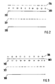
- 200 denotes a lower alarm limit, 201 a nominal value, 202 an upper alarm limit, 203 a test signal generator signal value and 204 a verification limit.
- the signal of the test generator it can now be checked whether the monitor detects a faulty signal, i.e. a signal that is above the upper alarm limit, and triggers an alarm.
- the verification limit 204 the measuring accuracy of the monitor is included in the signal test.
- a monitor fault flag is set. The intact monitor then independently takes over the monitoring function. If a monitor error is also recognized for this monitor in the further course, the navigation system is switched off by devices that are monitor-independent.
- 300 denotes a lower alarm limit, 301 a nominal value, 302 a value measured by monitor 2, 303 an upper alarm limit and 304 a value measured by monitor 1.
- Monitor 1 has thus recognized that the alarm limit has been exceeded, in other words that the signal emitted by the antenna system is faulty.
- a reduced alarm limit is introduced.
- the reduced alarm limit is the upper alarm limit reduced by a certain factor, for example 90% of the upper alarm limit. If the first monitor now detects an alarm situation and the second monitor detects a signal that is above the reduced alarm limit, the second monitor, the slave monitor, switches over from one transmitter to the other. This ensures that tolerance-related different statements made by the two monitors do not always result in the entire navigation system being switched off.
- the alarm limits used in the monitors are programmable. To increase the integrity of the system, the programmed alarm limits are automatically checked at regular intervals. It goes without saying that the alarm limits in the monitors can only be changed in the so-called bypass mode, that is to say when the navigation system is not being used to guide aircraft. In addition, precautions must be taken to ensure that no alarm limits are programmed which lead to malfunctions in the operation of the navigation system and thus to possible major accidents.
Landscapes
- Engineering & Computer Science (AREA)
- Computer Networks & Wireless Communication (AREA)
- Physics & Mathematics (AREA)
- General Physics & Mathematics (AREA)
- Radar, Positioning & Navigation (AREA)
- Remote Sensing (AREA)
- Radar Systems Or Details Thereof (AREA)
- Traffic Control Systems (AREA)
- Position Fixing By Use Of Radio Waves (AREA)
- Analysing Materials By The Use Of Radiation (AREA)
- Apparatus For Radiation Diagnosis (AREA)
Applications Claiming Priority (2)
| Application Number | Priority Date | Filing Date | Title |
|---|---|---|---|
| DE3938735 | 1989-11-23 | ||
| DE3938735A DE3938735A1 (de) | 1989-11-23 | 1989-11-23 | Einrichtung und verfahren zur ueberwachung einer navigationsanlage |
Publications (3)
| Publication Number | Publication Date |
|---|---|
| EP0429972A2 true EP0429972A2 (fr) | 1991-06-05 |
| EP0429972A3 EP0429972A3 (en) | 1992-05-06 |
| EP0429972B1 EP0429972B1 (fr) | 1995-04-26 |
Family
ID=6394000
Family Applications (1)
| Application Number | Title | Priority Date | Filing Date |
|---|---|---|---|
| EP90121871A Expired - Lifetime EP0429972B1 (fr) | 1989-11-23 | 1990-11-15 | Appareil et méthode de surveillance d'une installation de navigation |
Country Status (7)
| Country | Link |
|---|---|
| US (1) | US5130716A (fr) |
| EP (1) | EP0429972B1 (fr) |
| JP (1) | JP3043396B2 (fr) |
| AU (1) | AU637648B2 (fr) |
| CA (1) | CA2029247C (fr) |
| DE (2) | DE3938735A1 (fr) |
| NO (1) | NO177164C (fr) |
Cited By (1)
| Publication number | Priority date | Publication date | Assignee | Title |
|---|---|---|---|---|
| EP1953562A1 (fr) * | 2007-01-26 | 2008-08-06 | Kabushiki Kaisha Toshiba | Appareil de réception de contrôle VOR et procédé de réception de contrôle VOR |
Families Citing this family (11)
| Publication number | Priority date | Publication date | Assignee | Title |
|---|---|---|---|---|
| US5229776A (en) * | 1991-12-05 | 1993-07-20 | Allied-Signal Inc. | Method for field monitoring of a phased array microwave landing system far field antenna pattern employing a near field correction technique |
| US5254998A (en) * | 1992-11-02 | 1993-10-19 | Allied-Signal Inc. | Executive monitor for microwave landing system |
| DE19722913A1 (de) * | 1997-05-31 | 1998-12-03 | Alsthom Cge Alcatel | Gleitweg-Sendeeinrichtung für das Instrumentenlandesystem ILS |
| US5969664A (en) * | 1997-09-25 | 1999-10-19 | The United States Of America As Represented By The Secretary Of Commerce | Method for characterizing air traffic control radar beacon system antenna patterns |
| DE19756364A1 (de) | 1997-12-18 | 1999-06-24 | Cit Alcatel | Überwachung der Phasenlage von Course- und Clearance-Signalen bei einem Instrumentenlandesystem |
| DE19904842A1 (de) | 1999-02-08 | 2000-08-10 | Airsys Navigation Systems Gmbh | Überwachungssystem für terristrische Navigations- und Flughafenlandesysteme |
| JP3997988B2 (ja) * | 2001-05-31 | 2007-10-24 | オムロン株式会社 | 安全ユニット及びコントローラシステム並びにコントローラの連結方法及びコントローラシステムの制御方法 |
| WO2002097542A1 (fr) * | 2001-05-31 | 2002-12-05 | Omron Corporation | Esclave, systeme reseau, procede de traitement esclave, procede de collecte d'informations sur un appareil |
| EP1404061B1 (fr) * | 2001-06-22 | 2011-08-10 | Omron Corporation | Systeme de reseau securise et esclave securise |
| US7724259B2 (en) * | 2005-08-24 | 2010-05-25 | Innovative Solutions And Support, Inc. | Aircraft flat panel display system with improved information availability |
| DE102009032989A1 (de) * | 2009-07-14 | 2011-01-27 | Siemens Aktiengesellschaft | Hochverfügbares Bediengerät |
Family Cites Families (8)
| Publication number | Priority date | Publication date | Assignee | Title |
|---|---|---|---|---|
| US3085245A (en) * | 1956-12-10 | 1963-04-09 | Seismograph Service Corp | Automatic switchover system for radio transmitters |
| DE2505723C3 (de) * | 1975-02-12 | 1979-07-19 | Standard Elektrik Lorenz Ag, 7000 Stuttgart | Einrichtung zur Überwachung der von einer DVOR-Bodenstation abgestrahlten Trägerfrequenz- und Seitenbandsignale |
| DE3131494C2 (de) * | 1981-08-08 | 1983-05-11 | Standard Elektrik Lorenz Ag, 7000 Stuttgart | Überwachungseinrichtung für den Landekurssender eines Instrumentenlandesystems |
| FR2537806B1 (fr) * | 1982-12-10 | 1985-06-14 | Thomson Csf | Dispositif de commutation pour choisir un modulateur, parmi deux, et le brancher dans un emetteur, et emetteur de television comportant un tel dispositif |
| FR2582127B1 (fr) * | 1985-03-29 | 1994-05-20 | Thomson Csf | Procede et dispositif de surveillance d'une station d'un systeme d'aide a l'atterissage du type mls |
| GB2181317A (en) * | 1985-10-04 | 1987-04-15 | Philips Electronic Associated | Providing positional information |
| US4739351A (en) * | 1986-11-18 | 1988-04-19 | Hazeltine Corporation | Verification of on-line fault monitor performance |
| DE3810628C1 (fr) * | 1988-03-29 | 1989-04-06 | Standard Elektrik Lorenz Ag, 7000 Stuttgart, De |
-
1989
- 1989-11-23 DE DE3938735A patent/DE3938735A1/de not_active Withdrawn
-
1990
- 1990-11-02 CA CA002029247A patent/CA2029247C/fr not_active Expired - Lifetime
- 1990-11-12 NO NO904893A patent/NO177164C/no not_active IP Right Cessation
- 1990-11-13 AU AU66514/90A patent/AU637648B2/en not_active Expired
- 1990-11-15 DE DE59008966T patent/DE59008966D1/de not_active Expired - Lifetime
- 1990-11-15 EP EP90121871A patent/EP0429972B1/fr not_active Expired - Lifetime
- 1990-11-21 US US07/616,891 patent/US5130716A/en not_active Expired - Lifetime
- 1990-11-26 JP JP2318152A patent/JP3043396B2/ja not_active Expired - Lifetime
Non-Patent Citations (1)
| Title |
|---|
| PETER J. WROBLEWSKI: "DeveLopment of Continuity of Service Requirements for the Microwave Landing System", MITRE FIRMENVERÖFFENTLICHUNG, MTR-86W243, September 1987 (1987-09-01), pages 2 - 1 |
Cited By (2)
| Publication number | Priority date | Publication date | Assignee | Title |
|---|---|---|---|---|
| EP1953562A1 (fr) * | 2007-01-26 | 2008-08-06 | Kabushiki Kaisha Toshiba | Appareil de réception de contrôle VOR et procédé de réception de contrôle VOR |
| US7791531B2 (en) | 2007-01-26 | 2010-09-07 | Kabushiki Kaisha Toshiba | VOR monitoring receiving apparatus and VOR monitor receiving method |
Also Published As
| Publication number | Publication date |
|---|---|
| NO904893L (no) | 1991-05-24 |
| JP3043396B2 (ja) | 2000-05-22 |
| AU6651490A (en) | 1991-05-30 |
| NO177164B (no) | 1995-04-18 |
| CA2029247A1 (fr) | 1991-05-24 |
| NO177164C (no) | 1995-07-26 |
| NO904893D0 (no) | 1990-11-12 |
| JPH03188600A (ja) | 1991-08-16 |
| DE59008966D1 (de) | 1995-06-01 |
| DE3938735A1 (de) | 1991-05-29 |
| EP0429972A3 (en) | 1992-05-06 |
| CA2029247C (fr) | 1996-02-06 |
| US5130716A (en) | 1992-07-14 |
| EP0429972B1 (fr) | 1995-04-26 |
| AU637648B2 (en) | 1993-06-03 |
Similar Documents
| Publication | Publication Date | Title |
|---|---|---|
| DE3003291C2 (de) | Zweikanalige Datenverarbeitungsanordnung für Eisenbahnsicherungszwecke | |
| DE2701924C3 (de) | Steuereinrichtung für spurgebundene Fahrzeuge | |
| DE3222692A1 (de) | Elektrisches stromversorgungssystem | |
| DE102019112839B3 (de) | Schutz- und Überwachungseinrichtung in einer Ladeinfrastruktur zum Laden von elektrisch angetriebenen Fahrzeugen und Verfahren zur Überwachung einer Ladeinfrastruktur | |
| EP0429972B1 (fr) | Appareil et méthode de surveillance d'une installation de navigation | |
| DE4441070C2 (de) | Sicherheitsschalteranordnung | |
| DE3600092C2 (fr) | ||
| DE2833761B2 (de) | Schaltungsanordnung zur Überwachung des Zustande von Signalanlagen, insbesondere von StraBenverkehrs-Lichtsignalanlagen | |
| DE3419273C2 (fr) | ||
| EP0205014A2 (fr) | Dispositif de surveillance | |
| DE3627960C1 (en) | Monitoring device for loudspeaker installations | |
| DE3325362A1 (de) | Selbsttestende anordnung zum erzeugen von zeitverzoegerungen | |
| EP0059789B1 (fr) | Dispositif pour le test de fonctionnement d'un système à plusieurs calculateurs | |
| EP0270871B1 (fr) | Système pour l'entrée/sortie de signaux dans un système de commande digitale | |
| DE2400604B2 (de) | Elektronisches Fehleranzeigesystem | |
| DE69118099T2 (de) | Verfahren und Vorrichtung zum Testen eines Datenverarbeitungsmoduls und ihre Anwendung in der Fahrzeugelektronik | |
| DE3515962A1 (de) | Anordnung zur signaltechnisch sicheren steuerung und ausfallueberwachung wechselstromgespeister doppelfadenlampen eines lichtsignals, insbesondere vorsignals in eisenbahnsignalanlagen | |
| WO2021074373A1 (fr) | Agencement d'essai sûr | |
| DE4143097C3 (de) | Anordnung und Anzeige zur Ortsbestimmung defekter Lampen in Flugplatzbefeuerungsanlagen mit digitalem Lampen-"Intakt"-Signal | |
| DE3737445A1 (de) | Schaltungsanordnung zum ueberwachen eines niederohmigen elektrischen bauelementes auf unterbrechung | |
| DE4319750C2 (de) | Verfahren und Vorrichtung zur Funktionsüberwachung von Schalteinrichtungen einer Brückenschaltung sowie deren Verwendung | |
| DE69223454T2 (de) | Verfahren und Vorrichtung zum Verhindern des unautorisierten Betriebes von Hochspannungsgeräten | |
| DE2903383B1 (de) | Testgeraet fuer addressierbare digitale Schaltungen | |
| DE2948384C2 (de) | Sicherheitseinrichtung zur Geschwindigkeitsregelung für schienengebundene Fahrzeuge | |
| EP0281890B1 (fr) | Circuit logique séquentiel de sécurité à plusieurs microprocesseurs travaillant sur des données identiques |
Legal Events
| Date | Code | Title | Description |
|---|---|---|---|
| PUAI | Public reference made under article 153(3) epc to a published international application that has entered the european phase |
Free format text: ORIGINAL CODE: 0009012 |
|
| AK | Designated contracting states |
Kind code of ref document: A2 Designated state(s): DE FR GB IT |
|
| PUAL | Search report despatched |
Free format text: ORIGINAL CODE: 0009013 |
|
| AK | Designated contracting states |
Kind code of ref document: A3 Designated state(s): DE FR GB IT |
|
| 17P | Request for examination filed |
Effective date: 19920819 |
|
| RAP3 | Party data changed (applicant data changed or rights of an application transferred) |
Owner name: ALCATEL SEL AKTIENGESELLSCHAFT |
|
| 17Q | First examination report despatched |
Effective date: 19940627 |
|
| GRAA | (expected) grant |
Free format text: ORIGINAL CODE: 0009210 |
|
| AK | Designated contracting states |
Kind code of ref document: B1 Designated state(s): DE FR GB IT |
|
| REF | Corresponds to: |
Ref document number: 59008966 Country of ref document: DE Date of ref document: 19950601 |
|
| GBT | Gb: translation of ep patent filed (gb section 77(6)(a)/1977) |
Effective date: 19950515 |
|
| ITF | It: translation for a ep patent filed | ||
| ET | Fr: translation filed | ||
| PLBE | No opposition filed within time limit |
Free format text: ORIGINAL CODE: 0009261 |
|
| STAA | Information on the status of an ep patent application or granted ep patent |
Free format text: STATUS: NO OPPOSITION FILED WITHIN TIME LIMIT |
|
| 26N | No opposition filed | ||
| REG | Reference to a national code |
Ref country code: GB Ref legal event code: IF02 |
|
| PGFP | Annual fee paid to national office [announced via postgrant information from national office to epo] |
Ref country code: DE Payment date: 20091112 Year of fee payment: 20 |
|
| PGFP | Annual fee paid to national office [announced via postgrant information from national office to epo] |
Ref country code: FR Payment date: 20091123 Year of fee payment: 20 Ref country code: IT Payment date: 20091116 Year of fee payment: 20 Ref country code: GB Payment date: 20091111 Year of fee payment: 20 |
|
| REG | Reference to a national code |
Ref country code: GB Ref legal event code: PE20 Expiry date: 20101114 |
|
| PG25 | Lapsed in a contracting state [announced via postgrant information from national office to epo] |
Ref country code: GB Free format text: LAPSE BECAUSE OF EXPIRATION OF PROTECTION Effective date: 20101114 |
|
| PG25 | Lapsed in a contracting state [announced via postgrant information from national office to epo] |
Ref country code: DE Free format text: LAPSE BECAUSE OF EXPIRATION OF PROTECTION Effective date: 20101115 |