EP0430008B1 - Filtereinheit - Google Patents
Filtereinheit Download PDFInfo
- Publication number
- EP0430008B1 EP0430008B1 EP90122059A EP90122059A EP0430008B1 EP 0430008 B1 EP0430008 B1 EP 0430008B1 EP 90122059 A EP90122059 A EP 90122059A EP 90122059 A EP90122059 A EP 90122059A EP 0430008 B1 EP0430008 B1 EP 0430008B1
- Authority
- EP
- European Patent Office
- Prior art keywords
- casing
- pipe
- filter
- filter unit
- chamber
- Prior art date
- Legal status (The legal status is an assumption and is not a legal conclusion. Google has not performed a legal analysis and makes no representation as to the accuracy of the status listed.)
- Expired - Lifetime
Links
- 238000007789 sealing Methods 0.000 claims description 4
- 238000011144 upstream manufacturing Methods 0.000 claims description 4
- 238000001914 filtration Methods 0.000 description 7
- 238000004140 cleaning Methods 0.000 description 3
- 239000000428 dust Substances 0.000 description 3
- 230000007717 exclusion Effects 0.000 description 1
- 239000000945 filler Substances 0.000 description 1
- 238000009434 installation Methods 0.000 description 1
- 239000000463 material Substances 0.000 description 1
- 238000010422 painting Methods 0.000 description 1
- 238000005192 partition Methods 0.000 description 1
Images
Classifications
-
- B—PERFORMING OPERATIONS; TRANSPORTING
- B01—PHYSICAL OR CHEMICAL PROCESSES OR APPARATUS IN GENERAL
- B01D—SEPARATION
- B01D46/00—Filters or filtering processes specially modified for separating dispersed particles from gases or vapours
- B01D46/02—Particle separators, e.g. dust precipitators, having hollow filters made of flexible material
- B01D46/04—Cleaning filters
-
- B—PERFORMING OPERATIONS; TRANSPORTING
- B01—PHYSICAL OR CHEMICAL PROCESSES OR APPARATUS IN GENERAL
- B01D—SEPARATION
- B01D46/00—Filters or filtering processes specially modified for separating dispersed particles from gases or vapours
- B01D46/56—Filters or filtering processes specially modified for separating dispersed particles from gases or vapours with multiple filtering elements, characterised by their mutual disposition
- B01D46/58—Filters or filtering processes specially modified for separating dispersed particles from gases or vapours with multiple filtering elements, characterised by their mutual disposition connected in parallel
-
- B—PERFORMING OPERATIONS; TRANSPORTING
- B01—PHYSICAL OR CHEMICAL PROCESSES OR APPARATUS IN GENERAL
- B01D—SEPARATION
- B01D46/00—Filters or filtering processes specially modified for separating dispersed particles from gases or vapours
- B01D46/66—Regeneration of the filtering material or filter elements inside the filter
- B01D46/74—Regeneration of the filtering material or filter elements inside the filter by forces created by movement of the filter element
- B01D46/76—Regeneration of the filtering material or filter elements inside the filter by forces created by movement of the filter element involving vibrations
-
- B—PERFORMING OPERATIONS; TRANSPORTING
- B01—PHYSICAL OR CHEMICAL PROCESSES OR APPARATUS IN GENERAL
- B01D—SEPARATION
- B01D46/00—Filters or filtering processes specially modified for separating dispersed particles from gases or vapours
- B01D46/90—Devices for taking out of action one or more units of multi-unit filters, e.g. for regeneration or maintenance
Definitions
- This invention relates to a filter unit, the component parts of which are combined and formed in such a manner as to provide it with particularly useful characteristics.
- the invention finds particular application in working environments using dust-generating machines, such as orbital tools used for sanding filler material in vehicle body shops before painting.
- EP-A-0087191 and DE-A-2815960 disclose filter units having at least two compartments each provided with filtering hoses extending from a horizontal partition dividing the filter shell into a lowermost portion communicating with an inlet pipe for air with dust to be filtered off, and into an uppermost portion forming separate chambers communicating with a suction pipe through respective valves.
- a source of compressed air communicating with the above mentioned chambers through pipes having shutoff valves which are opened one at a time to feed compressed air into one of the chambers when and while the valve through which said chamber communicates with the suction pipe is closed. In this way the direction of the flow of air passing through the filtering hoses of the involved compartment is reversed and the dust layer deposited on the filter hoses is detached therefrom.
- An object of the present invention is to provide a filter unit of the aforesaid type which totally overcomes the stated drawbacks of conventional filter units.
- Such filter unit comprises a casing (2) containing filter tubes (5) suspended from a filter-support surface (6), an inlet pipe (10) associated with said casing (2) at the upstream side of said surface (6) where said tubes (5) extend, an outlet suction pipe (11) associated with said casing (2) at the other side of said surface (6), at least two chambers (13, 13') separated by sealing diaphragms (14) downstream of said surface (6) and each independently connected to said suction pipe (11), and shutoff valves (18, 18') provided between said outlet suction pipe (11) and each respective chamber (13, 13') to control the air flow through said filter tubes (5), characterized in that for each part of the surface (6) associated with each chamber (13, 13') shaker means (7) are provided comprising a pipe segment suspended from said surface (6), an inlet pipe (9) at the upstream side of said support surface (6) being connected with the bottom end of said pipe segment to feed compressed air therein and to cause a ball (8) contained within the pipe segment to move energetically therein,
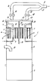
- the filter unit is of the type comprising a casing 2 of circular cross-section associated with a dust container 3, said casing housing a filter unit indicated overall by 4 and conventionally consisting of a plurality of vertically arranged filter tubes 5 suspended from a surface 6 carrying shaker means 7 of ball type.
- the shaker means 7 each comprise a ball 8 caused to move energetically by compressed air fed through the pipe 9.
- a suction pipe 10 is provided in the lateral surface of the lower part of the casing 2. Draw-off from the casing 2 is provided by a conventional turbine (not shown) associated with a pipe 11.
- the interior of the casing 2 between the filtering surface 6 and the upper cover 12 is in the form of two separate compartments 13, 13' separated by a sealing diaphragm 14, each chamber comprising an outlet aperture 15, 15' to which there is connected a tube branch 16, 16 which at 17 meets the turbine suction pipe 11, the cross-sections of the branches 16 and 16' being equal to the cross-sections of the pipes 11 and 10.
- the branches 16 and 16' are each provided with their own valve 18, 18' and the casing 2 comprises a vertical dividing wall 19 interposed between the filters 5 in a position corresponding to the diaphragm 14.
- the shaker means 7 conventionally comprise discharge pipes 20 to the outside.
- the use of the described structure means that the passage cross-section of that surface 6 relative to the chamber 13 can be kept equal to the cross-section of the remaining pipes as the filtering surface relative to said chamber 13 is kept permanently clean because of the facility for alternating draw-off via the chamber 13 or via the chamber 13' as required, by simply closing one or other of the branches 16, 16'.
- the cleaning of the one or the other chamber is effected by operating the shaker means 7 during the exclusion of the one or the other chamber.
Landscapes
- Chemical & Material Sciences (AREA)
- Chemical Kinetics & Catalysis (AREA)
- Filtering Of Dispersed Particles In Gases (AREA)
- Electrical Discharge Machining, Electrochemical Machining, And Combined Machining (AREA)
Claims (3)
- Filtereinheit, umfassend ein Gehäuse (2), das Filterrohre bzw. -schläuche (5) enthält, die von einer Filterhaltefiäche (6) her aufgehängt sind, ein Einlaßrohr (10), das mit dem Gehäuse (2) an der stromaufwärtigen Seite der Fläche (6), wo sich die Rohre bzw. Schläuche (5) erstrecken, verbunden ist, ein Auslaßsaugrohr (11), das mit dem Gehäuse (2) an der anderen Seite der Fläche (6) verbunden ist, wenigstens zwei durch Abdichtungsscheidewände (14) getrennte Kammern (13, 13') stromabwärts von der Fläche (6) und jede unabhängig mit dem Saugrohr (11) verbunden, und Absperrventile (18, 18'), die zwischen dem Auslaßsaugrohr (11) und jeder jeweiligen Kammer (13, 13') zum Steuern der Luftströmung durch die Filterrohre bzw. -schläuche (5) vorgesehen sind, dadurch gekennzeichnet, daß für jeden Teil der Fläche (6), der mit einer jeweiligen Kammer (13, 13') verbunden ist, Rüttlermittel (7) vorgesehen sind, umfassend einen Rohrabschnitt, der von der Fläche (6) her aufgehängt ist, ein Einlaßrohr (9) an der stromaufwärtigen Seite der Haltefläche (6), das mit dem unteren Ende des Rohrabschnitts verbunden ist, um Druckiuft darein zuzuführen und zu bewirken, daß sich eine Kugel (8), die innerhalb des Rohrabschnitts enthalten ist, energetisch darin bewegt, und ein Entladungsrohr (20), das sich durch die jeweilige Kammer (13, 13') erstreckt und das obere Ende des Rohrabschnitts mit dem Äußeren des Gehäuses (2) verbindet, auch vorgesehen ist, wobei die Rüttlermittel (7) nur betreibbar sind, wenn das entsprechende Ventil (18, 18') geschlossen ist.
- Filtereinheit gemäß Anspruch 1, dadurch gekennzeichnet, daß jede Kammer (13, 13') mit dem Saugrohr (11) mittels einer Abzweigung (16, 16') verbunden ist, wobei jede Abzweigung ihr eigenes Absperrventil (18, 18') enthält.
- Filtereinheit gemäß den Ansprüchen 1 und 2, dadurch gekennzeichnet, daß das Gehäuse (2) vertikal angeordnet und von der Fläche (6) her aufgehängt eine Anzahl von Unterteilungswänden (19) gleich der Anzahl von Abdichtungsscheidewänden (14), welche die Kammern (13, 13') begrenzen, umfaßt.
Applications Claiming Priority (2)
| Application Number | Priority Date | Filing Date | Title |
|---|---|---|---|
| IT2216989 | 1989-11-29 | ||
| IT22169U IT219038Z2 (it) | 1989-11-29 | 1989-11-29 | Gruppo filtrante ad elevato rendimento volumetrico e ridotta superficie filtrante |
Publications (2)
| Publication Number | Publication Date |
|---|---|
| EP0430008A1 EP0430008A1 (de) | 1991-06-05 |
| EP0430008B1 true EP0430008B1 (de) | 1994-09-07 |
Family
ID=11192530
Family Applications (1)
| Application Number | Title | Priority Date | Filing Date |
|---|---|---|---|
| EP90122059A Expired - Lifetime EP0430008B1 (de) | 1989-11-29 | 1990-11-19 | Filtereinheit |
Country Status (4)
| Country | Link |
|---|---|
| US (1) | US5114583A (de) |
| EP (1) | EP0430008B1 (de) |
| DE (1) | DE69012283T2 (de) |
| IT (1) | IT219038Z2 (de) |
Families Citing this family (5)
| Publication number | Priority date | Publication date | Assignee | Title |
|---|---|---|---|---|
| US5251384A (en) * | 1991-06-28 | 1993-10-12 | Glatt Air Techniques, Inc. | Fluidized bed apparatus including double chamber cartridge filter system |
| US5577837A (en) * | 1995-05-19 | 1996-11-26 | Forma Scientific, Inc. | Temperature controlled HEPA-filtered console shaker |
| US6217781B1 (en) | 1998-05-05 | 2001-04-17 | Russell B. Hobson, Jr. | Applications for slack filter tube with tensioning means |
| US6309552B1 (en) | 1998-05-05 | 2001-10-30 | Russell B. Hobson, Jr. | Slack filter tube having an internal resilient support extending there through |
| EP1029576A1 (de) * | 1999-02-18 | 2000-08-23 | Jetclean GmbH | Vorrichtung zur Reinigung eines Filters |
Family Cites Families (8)
| Publication number | Priority date | Publication date | Assignee | Title |
|---|---|---|---|---|
| US2014298A (en) * | 1932-09-01 | 1935-09-10 | Claude B Schneible | Dust arrester |
| JPS4993966A (de) * | 1973-01-13 | 1974-09-06 | ||
| DE2815960A1 (de) * | 1978-04-13 | 1979-10-31 | Procedyne Corp | Wirbelbett und ein verfahren zu seiner ausnutzung |
| SE426915B (sv) * | 1981-02-10 | 1983-02-21 | Patronax Ab | Filteranordnng med slagmekanism vilken medger rensning av ett i anordningeningaende filters filtermedium fran ur luft avskilt stoft |
| NL8200551A (nl) * | 1982-02-12 | 1983-09-01 | Brabant D Van Opstal B V Masch | Stoffilter. |
| US4502874A (en) * | 1982-10-08 | 1985-03-05 | Pneumafil Corporation | Continuous filtration |
| CS242625B1 (en) * | 1983-08-04 | 1986-05-15 | Jiri Albrecht | Industry filter |
| US4919801A (en) * | 1988-01-07 | 1990-04-24 | Hobson Jr Russell | Control system for pump cycling |
-
1989
- 1989-11-29 IT IT22169U patent/IT219038Z2/it active IP Right Grant
-
1990
- 1990-11-19 DE DE69012283T patent/DE69012283T2/de not_active Expired - Fee Related
- 1990-11-19 EP EP90122059A patent/EP0430008B1/de not_active Expired - Lifetime
- 1990-11-20 US US07/616,203 patent/US5114583A/en not_active Expired - Fee Related
Also Published As
| Publication number | Publication date |
|---|---|
| DE69012283D1 (de) | 1994-10-13 |
| EP0430008A1 (de) | 1991-06-05 |
| IT8922169V0 (it) | 1989-11-29 |
| IT8922169U1 (it) | 1991-05-29 |
| US5114583A (en) | 1992-05-19 |
| IT219038Z2 (it) | 1992-11-27 |
| DE69012283T2 (de) | 1995-01-19 |
Similar Documents
| Publication | Publication Date | Title |
|---|---|---|
| CN1061566C (zh) | 旋流粉尘收集器 | |
| US4511471A (en) | Filter apparatus for continuously thickening suspensions | |
| EP0274783B1 (de) | Schleuderstrahlvorrichtung | |
| US4395269B1 (en) | Compact dust filter assembly | |
| US4759781A (en) | Filtering and dust collecting apparatus | |
| US3784016A (en) | Automatic continuously backflow washing-type filter | |
| US4388087A (en) | Cyclonic separator-filter | |
| EP0172538B1 (de) | Flächenfilter mit Staubsammler für abwärts gerichtete Strömung | |
| CN113082891B (zh) | 一种节能型空分设备压缩系统自洁式过滤器 | |
| EP0430008B1 (de) | Filtereinheit | |
| GB1445810A (en) | Apparatus for separating dust from a dust-containing gas | |
| US2616517A (en) | Tank type cleaner | |
| US3097938A (en) | Gas-material separator | |
| CN109603337A (zh) | 一种提升门板式气流清灰袋式除尘器 | |
| US5571299A (en) | Dust collector | |
| US6290737B1 (en) | Dust filter | |
| US4637825A (en) | Filter system for power sweeper | |
| AU622913B2 (en) | Filter element | |
| US540720A (en) | Dust-collector | |
| US2674342A (en) | Apparatus for reverse flow cleaning of filters | |
| KR200487433Y1 (ko) | 산업용 청소기 | |
| CN1009334B (zh) | 空气净化器 | |
| US5676281A (en) | Fluid flow airlock valve | |
| EP0947232B1 (de) | Filter mit Druckventil zum Abscheiden von Öl aus Luft für Druckluftbeschaffungsanlagen | |
| WO1997040916A1 (en) | Device for bag house filter |
Legal Events
| Date | Code | Title | Description |
|---|---|---|---|
| PUAI | Public reference made under article 153(3) epc to a published international application that has entered the european phase |
Free format text: ORIGINAL CODE: 0009012 |
|
| AK | Designated contracting states |
Kind code of ref document: A1 Designated state(s): BE CH DE ES FR GB LI NL |
|
| 17P | Request for examination filed |
Effective date: 19911129 |
|
| 17Q | First examination report despatched |
Effective date: 19930607 |
|
| GRAA | (expected) grant |
Free format text: ORIGINAL CODE: 0009210 |
|
| AK | Designated contracting states |
Kind code of ref document: B1 Designated state(s): BE CH DE ES FR GB LI NL |
|
| PG25 | Lapsed in a contracting state [announced via postgrant information from national office to epo] |
Ref country code: NL Effective date: 19940907 Ref country code: LI Effective date: 19940907 Ref country code: ES Free format text: THE PATENT HAS BEEN ANNULLED BY A DECISION OF A NATIONAL AUTHORITY Effective date: 19940907 Ref country code: CH Effective date: 19940907 Ref country code: BE Effective date: 19940907 |
|
| REF | Corresponds to: |
Ref document number: 69012283 Country of ref document: DE Date of ref document: 19941013 |
|
| RAP2 | Party data changed (patent owner data changed or rights of a patent transferred) |
Owner name: BLACKHAWK ITALIA S.R.L. |
|
| ET | Fr: translation filed | ||
| REG | Reference to a national code |
Ref country code: CH Ref legal event code: PL |
|
| NLV1 | Nl: lapsed or annulled due to failure to fulfill the requirements of art. 29p and 29m of the patents act | ||
| PLBE | No opposition filed within time limit |
Free format text: ORIGINAL CODE: 0009261 |
|
| STAA | Information on the status of an ep patent application or granted ep patent |
Free format text: STATUS: NO OPPOSITION FILED WITHIN TIME LIMIT |
|
| 26N | No opposition filed | ||
| PGFP | Annual fee paid to national office [announced via postgrant information from national office to epo] |
Ref country code: FR Payment date: 19960215 Year of fee payment: 6 |
|
| PGFP | Annual fee paid to national office [announced via postgrant information from national office to epo] |
Ref country code: GB Payment date: 19960219 Year of fee payment: 6 |
|
| PGFP | Annual fee paid to national office [announced via postgrant information from national office to epo] |
Ref country code: DE Payment date: 19960223 Year of fee payment: 6 |
|
| PG25 | Lapsed in a contracting state [announced via postgrant information from national office to epo] |
Ref country code: GB Effective date: 19961119 |
|
| REG | Reference to a national code |
Ref country code: GB Ref legal event code: 732E |
|
| GBPC | Gb: european patent ceased through non-payment of renewal fee |
Effective date: 19961119 |
|
| PG25 | Lapsed in a contracting state [announced via postgrant information from national office to epo] |
Ref country code: FR Effective date: 19970731 |
|
| PG25 | Lapsed in a contracting state [announced via postgrant information from national office to epo] |
Ref country code: DE Effective date: 19970801 |
|
| REG | Reference to a national code |
Ref country code: FR Ref legal event code: ST |