EP0430123A1 - Hochspannungsschalter mit Varistoren - Google Patents
Hochspannungsschalter mit Varistoren Download PDFInfo
- Publication number
- EP0430123A1 EP0430123A1 EP90122515A EP90122515A EP0430123A1 EP 0430123 A1 EP0430123 A1 EP 0430123A1 EP 90122515 A EP90122515 A EP 90122515A EP 90122515 A EP90122515 A EP 90122515A EP 0430123 A1 EP0430123 A1 EP 0430123A1
- Authority
- EP
- European Patent Office
- Prior art keywords
- varistor
- circuit breaker
- resistor
- column
- breaker according
- Prior art date
- Legal status (The legal status is an assumption and is not a legal conclusion. Google has not performed a legal analysis and makes no representation as to the accuracy of the status listed.)
- Granted
Links
- 239000003990 capacitor Substances 0.000 claims abstract description 4
- HBMJWWWQQXIZIP-UHFFFAOYSA-N silicon carbide Chemical compound [Si+]#[C-] HBMJWWWQQXIZIP-UHFFFAOYSA-N 0.000 claims description 4
- 229910010271 silicon carbide Inorganic materials 0.000 claims description 3
- 235000014692 zinc oxide Nutrition 0.000 claims description 3
- RNWHGQJWIACOKP-UHFFFAOYSA-N zinc;oxygen(2-) Chemical class [O-2].[Zn+2] RNWHGQJWIACOKP-UHFFFAOYSA-N 0.000 claims description 3
- 150000001875 compounds Chemical class 0.000 claims description 2
- 239000000463 material Substances 0.000 claims description 2
- 239000002184 metal Substances 0.000 description 16
- 229910052751 metal Inorganic materials 0.000 description 16
- 239000000919 ceramic Substances 0.000 description 3
- OKTJSMMVPCPJKN-UHFFFAOYSA-N Carbon Chemical compound [C] OKTJSMMVPCPJKN-UHFFFAOYSA-N 0.000 description 2
- 229910018503 SF6 Inorganic materials 0.000 description 2
- 229910052799 carbon Inorganic materials 0.000 description 2
- SFZCNBIFKDRMGX-UHFFFAOYSA-N sulfur hexafluoride Chemical compound FS(F)(F)(F)(F)F SFZCNBIFKDRMGX-UHFFFAOYSA-N 0.000 description 2
- 229960000909 sulfur hexafluoride Drugs 0.000 description 2
- 239000004593 Epoxy Substances 0.000 description 1
- 230000000712 assembly Effects 0.000 description 1
- 238000000429 assembly Methods 0.000 description 1
- 238000003776 cleavage reaction Methods 0.000 description 1
- 239000012530 fluid Substances 0.000 description 1
- 239000011521 glass Substances 0.000 description 1
- 239000011810 insulating material Substances 0.000 description 1
- 238000009413 insulation Methods 0.000 description 1
- 239000007788 liquid Substances 0.000 description 1
- 230000007246 mechanism Effects 0.000 description 1
- 238000000465 moulding Methods 0.000 description 1
- 230000021715 photosynthesis, light harvesting Effects 0.000 description 1
- 229920001296 polysiloxane Polymers 0.000 description 1
- 229910052573 porcelain Inorganic materials 0.000 description 1
- 230000001737 promoting effect Effects 0.000 description 1
- 230000007017 scission Effects 0.000 description 1
- 229920002994 synthetic fiber Polymers 0.000 description 1
- 230000007704 transition Effects 0.000 description 1
Images



Classifications
-
- H—ELECTRICITY
- H01—ELECTRIC ELEMENTS
- H01H—ELECTRIC SWITCHES; RELAYS; SELECTORS; EMERGENCY PROTECTIVE DEVICES
- H01H33/00—High-tension or heavy-current switches with arc-extinguishing or arc-preventing means
- H01H33/02—Details
- H01H33/04—Means for extinguishing or preventing arc between current-carrying parts
- H01H33/16—Impedances connected with contacts
- H01H33/161—Variable impedances
-
- H—ELECTRICITY
- H01—ELECTRIC ELEMENTS
- H01H—ELECTRIC SWITCHES; RELAYS; SELECTORS; EMERGENCY PROTECTIVE DEVICES
- H01H33/00—High-tension or heavy-current switches with arc-extinguishing or arc-preventing means
- H01H33/02—Details
- H01H33/04—Means for extinguishing or preventing arc between current-carrying parts
- H01H33/14—Multiple main contacts for the purpose of dividing the current through, or potential drop along, the arc
- H01H2033/146—Multiple main contacts for the purpose of dividing the current through, or potential drop along, the arc using capacitors, e.g. for the voltage division over the different switches
Definitions
- the present invention relates to a high voltage circuit breaker with varistors.
- High voltage circuit breakers which are equipped with varistors, in particular for operating the shunt reactors of the electrical networks; the purpose of the presence of varistors, also called non-linear or variable resistors or resistors depending on the voltage, is to reduce overvoltages.
- the desired overvoltage limit is often in the range of 1.5 to 1.6 p.u.
- the current can be 5 / IO OOO ampere
- the current can exceed 2,000 amps.
- the energy dissipated in the varistors reaches several thousand kilojoules.
- An object of the present invention is to provide a high voltage circuit breaker with varistors allowing the solution of this problem.
- the subject of the invention is a high voltage circuit breaker comprising at least one breaking chamber and, in parallel on this breaking chamber, on the one hand a varistor in series with a switch and, on the other hand, a distribution capacitor, characterized in that a purely ohmic resistance, of value between 30 and 300 ohms, is inserted in series with said varistor.
- the resistor is formed by a first stack of discs disposed in an insulating tube in which the varistor is placed in the form of a second stack of discs, said tube being placed inside an insulating column filled with a gas having good dielectric properties.
- said resistor is formed by a stack of discs placed in an insulating tube, said tube being arranged horizontally and being connected mechanically and electrically, on one side to a column containing the main breaking chamber and, on the other side, to a column containing the varistor.
- the resistance formed by rods and the varistor are housed side by side in the insulating envelope which overcomes the main breaking chamber.
- the varistor is arranged in a column provided with a cover having a horizontal extension containing the associated resistance, the extension being closed by a bottom provided with current outlet.
- the cover having an extension containing the resistance overcomes the main chamber.
- the varistor material is chosen from compounds based on zinc oxides and silicon carbide.
- the reference L designates a phase of a high-voltage line into which a circuit breaker is inserted comprising, for each phase, two interrupting chambers in series 1 and 2.
- the breaking chambers are, as is well known, made up of a insulating column filled with a gas with high dielectric strength such as sulfur hexafluoride, under a pressure of a few bars.
- each of the switching chambers In parallel on each of the switching chambers are arranged insulating columns C1 and C2 respectively; these columns contain a gas or a dielectric liquid and house a capacitor and intended for the distribution of the voltage between the two breaking chambers.
- Each chamber comprises in parallel another column, respectively K1 and K2, inside which there are, connected in series, a varistor (V1, V2) and a switch (I1, I2).
- a Is corresponds a threshold voltage Us of the varistor.
- the internal resistance of the varistor to this threshold is:
- Ra 80 ohms, or 40 ohms for each of the resistors R1 and R2.
- the total duration of transition to 700 A peak in phase opposition can be estimated at 6 milliseconds.
- resistors R1 and R2 which, in general, will be between 30 and 300 ohms
- the thermal energy dissipated by the resistor during operation in phase opposition will be approximately: about 60,000 joules
- additional resistors are not valid for the protection of phase-to-earth faults. Indeed, during a lightning strike on the line, the presence of additional resistors prevents the rapid flow of charges. A high overvoltage then occurs on the resistor, given the large intensity of the discharge current which can reach ten kiloamperes, and the high speed of current increase.
- connection between the resistor and the varistor must be as short as possible.
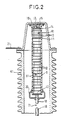
- Figure 2 is a partial view in axial section of the column K1 containing in particular the varistor V1 and the resistor R1.
- the varistor V1 consists of a stack of discs 10 based on zinc oxides or on silicon carbide (CSi); the top and the base of the stack are closed by metal disks, 11 and 12 respectively.
- the resistor R1 consists of a stack of discs 13, for example made of conductive ceramic based on carbon.
- the stack is placed directly above the metal disc 11, and is in contact at its upper part with a metal disc 14.
- a spring 15 presses the disc 14 against the stack R1 by pressing on the inside of a cover metal 16 closing the column K1.
- a metal braid 17 ensures the passage of current between the cover 16 and the disc 14.
- the reference 18 designates the fixed contact of the switch II and the reference 19 the end of the movable contact; as the embodiment of the switch is well known and goes beyond the scope of the present invention, the switch has not been shown in detail.
- the cover 16 is electrically connected by a link 21 to the top of the main breaking chamber 1, not shown in FIG. 2, but shown diagrammatically in FIG. 1.
- column K1 The interior of column K1 is filled with a gas with good dielectric properties promoting cleavage, such as pure or mixed sulfur hexafluoride, under a pressure of a few bars.
- a gas with good dielectric properties promoting cleavage such as pure or mixed sulfur hexafluoride
- FIG. 3 partially represents columns 1 and K1, the resistor R1 being arranged this time outside these columns.
- the varistor V1 always consists of a stack of discs 10, surmounted by a metal disc 25 pressed by a spring 28 bearing on a metal cover 27 closing the column K1.
- a metal braid 28 between the disc 25 and the cover 27 ensures the passage of current.
- Resistor R1 is formed by a stack of discs 13 placed in an insulating tube 30, for example made of epoxy glass, which can be provided with fins 31, for example made of silicone.
- the tube 30 is hermetically closed at its ends by metal plates 32 and 33; the discs 13 are pressed by a spring 34 bearing between the plate 32 and a metal disc 35 at the end of the stack; a metal braid 36, between the plate 32 and the disc 35, ensures the passage of current.
- the tube 30 is arranged horizontally, between the columns 1 and K1, to which it is mechanically and electrically connected.
- connections 37 and 38 respectively connect on the one hand the plate 32 and the metal top 39 of the column 1, and on the other hand the plate 33 and the cover 27.
- Resistor R1 only sees current flow for a very short time. In the "open" or “closed” position of the circuit breaker, the connections 37 and 38 are at the same potential; there is therefore no permanent voltage on the resistor R1.
- the discs 13 can be formed in a single block and closed by molding in a synthetic envelope.
- FIG. 4 illustrates an alternative embodiment, in which the varistor V1 and the resistor R1 are housed in the casing 1 containing the main breaking chamber.
- the varistor V1 is formed by a stack of discs 10 placed in a tube 40 fixed to the cover 41 of the column 1. This cover is placed at the top of a cylindrical insulating envelope 42 provided with fins 43; this envelope, which surmounts column 1, can be made of porcelain or of insulating synthetic material.
- the stacking of the discs 10 is surmounted by a metal disc 44 serving to support a spring 45 which also bears against the cover 41.
- the lower part of the tube 40 serves as a support for the semi-fixed contact for inserting the varistor, as has been described for example in French patent 81 16 291.
- the resistor R1 is formed by one or more rods 70 of small diameter based on carbon (ceramic resistor), housed in insulating tubes 71 and fixed between the cover 41 and the socket 51 of the chamber 1. The number of sticks depends on the energy to be absorbed.
- Reference 52 designates the fixed contact tube for the passage of permanent current.
- FIG. 5 illustrates another embodiment of the invention, for a circuit breaker with two interrupting chambers per phase.
- the elements common to FIG. 5 and to FIG. 1 have been given the same reference numbers or signs.
- Varistors V1 and V2 are arranged in columns K1 and K2 respectively; they are maintained by insulating supports, 81 and 82, fixed to the metal covers 91 and 92 surmounting the columns K1 and K2.
- the metal covers 91 and 92 have horizontal cylindrical extensions 91A and 92A in which the resistors R1 and R2 are housed respectively.
- the resistors R1 and R2 are fixed, on the one hand to the supports 81 and 82, on the other hand to metallic bottoms 91B, 92B closing the cylinders 91A, 92A.
- the bottoms 91B, 92B have current sockets 91C, 92C, connected by a connection tube 94 for placing the two interrupting chambers 1 and 2 in series.
- the columns K1 and K2 and the cylindrical extensions of the covers form sealed assemblies filled with dielectric gas.
- the varistor-resistance pairs, V1, R1 and V2, R2, are found in the same dielectric fluid.
- cover 91 with its horizontal cylindrical extension 91A can very well also be mounted on the insulating casing 1 of the main chamber.
- the invention applies to high voltage circuit breakers and in particular to reactance circuit breakers.
Landscapes
- Arc-Extinguishing Devices That Are Switches (AREA)
- Thermistors And Varistors (AREA)
- Driving Mechanisms And Operating Circuits Of Arc-Extinguishing High-Tension Switches (AREA)
- Emergency Protection Circuit Devices (AREA)
- Electrophonic Musical Instruments (AREA)
- Circuit Arrangements For Discharge Lamps (AREA)
- Discharge Lamp (AREA)
- Organic Insulating Materials (AREA)
- Circuit Breakers (AREA)
- Bipolar Transistors (AREA)
Applications Claiming Priority (2)
| Application Number | Priority Date | Filing Date | Title |
|---|---|---|---|
| FR8915713 | 1989-11-29 | ||
| FR8915713A FR2655188B1 (fr) | 1989-11-29 | 1989-11-29 | Disjoncteur a haute tension a varistances. |
Publications (2)
| Publication Number | Publication Date |
|---|---|
| EP0430123A1 true EP0430123A1 (de) | 1991-06-05 |
| EP0430123B1 EP0430123B1 (de) | 1994-10-12 |
Family
ID=9387918
Family Applications (1)
| Application Number | Title | Priority Date | Filing Date |
|---|---|---|---|
| EP90122515A Expired - Lifetime EP0430123B1 (de) | 1989-11-29 | 1990-11-26 | Hochspannungsschalter mit Varistoren |
Country Status (10)
| Country | Link |
|---|---|
| US (1) | US5124872A (de) |
| EP (1) | EP0430123B1 (de) |
| JP (1) | JPH06101277B2 (de) |
| CN (1) | CN1024969C (de) |
| AT (1) | ATE112887T1 (de) |
| BR (1) | BR9006024A (de) |
| CA (1) | CA2030980C (de) |
| DE (1) | DE69013295T2 (de) |
| ES (1) | ES2064589T3 (de) |
| FR (1) | FR2655188B1 (de) |
Cited By (3)
| Publication number | Priority date | Publication date | Assignee | Title |
|---|---|---|---|---|
| FR2680043A1 (fr) * | 1991-08-02 | 1993-02-05 | Alsthom Gec | Disjoncteur a coupure multiple equipe de varistances. |
| EP0536039A1 (de) * | 1991-10-02 | 1993-04-07 | Gec Alsthom Sa | Ultra-Hochspannungsschalter |
| FR2688623A1 (fr) * | 1992-03-13 | 1993-09-17 | Asea Brown Boveri | Interrupteur de reacteur. |
Families Citing this family (19)
| Publication number | Priority date | Publication date | Assignee | Title |
|---|---|---|---|---|
| FR2668648B1 (fr) * | 1990-10-24 | 1992-12-24 | Alsthom Gec | Disjoncteur a sf6 a condensateur incorpore. |
| FR2674984B1 (fr) * | 1991-04-05 | 1993-06-11 | Alsthom Gec | Disjoncteur a sf6 a varistance et a condensateur incorpores. |
| JPH0576136A (ja) * | 1991-09-13 | 1993-03-26 | Hitachi Ltd | 電力供給系統 |
| SE510178C2 (sv) * | 1991-09-16 | 1999-04-26 | Asea Brown Boveri | Ventilavledaranordning |
| EP0555144A1 (de) * | 1992-02-07 | 1993-08-11 | Gec Alsthom Sa | Pumpstation |
| US6236010B1 (en) | 1999-07-14 | 2001-05-22 | Southern States, Inc. | Circuit interrupter including a penetrating electrical contact with grip and release structure |
| US6316742B1 (en) | 1999-07-14 | 2001-11-13 | Southern States, Inc. | Limited restrike circuit interrupter used as a line capacitor and load switch |
| CN101217078B (zh) * | 2008-01-04 | 2011-06-01 | 西安交通大学 | 一种带串联电阻的永磁机构真空断路器组合装置 |
| US8426736B2 (en) * | 2009-07-17 | 2013-04-23 | The Invention Science Fund I Llc | Maintaining insulators in power transmission systems |
| US8692537B2 (en) * | 2009-07-17 | 2014-04-08 | The Invention Science Fund I, Llc | Use pairs of transformers to increase transmission line voltage |
| US20110011621A1 (en) * | 2009-07-17 | 2011-01-20 | Searete Llc, A Limited Liability Corporation Of The State Of Delaware | Smart link coupled to power line |
| JP2013197010A (ja) * | 2012-03-22 | 2013-09-30 | Toshiba Corp | ガス遮断器 |
| CN103578843A (zh) * | 2013-11-08 | 2014-02-12 | 西安盟创电器有限公司 | 不重燃断路器 |
| DE102019212106A1 (de) | 2019-08-13 | 2021-02-18 | Siemens Energy Global GmbH & Co. KG | Schaltgeräte mit zwei in Reihe geschalteten Unterbrechereinheiten |
| GB201913695D0 (en) * | 2019-09-23 | 2019-11-06 | Oxford Instruments Nanotechnology Tools Ltd | Quench protection arrangement |
| CN111696817A (zh) * | 2020-03-25 | 2020-09-22 | 天津平高智能电气有限公司 | 一种高压开关及其壳体 |
| CN112382527B (zh) * | 2020-12-01 | 2023-12-19 | 郑州大学 | 一种多断口真空断路器动态电荷补偿的自均压控制方法 |
| EP4468584A1 (de) * | 2023-05-25 | 2024-11-27 | Siemens Energy Global GmbH & Co. KG | Zellbasierter modularer bremsteller für mittel- und hochspannungsanwendungen |
| DE102023207755A1 (de) * | 2023-08-11 | 2025-02-13 | Siemens Energy Global GmbH & Co. KG | Dead-Tank-Hochspannungs-Leistungsschalter |
Citations (5)
| Publication number | Priority date | Publication date | Assignee | Title |
|---|---|---|---|---|
| GB565410A (en) * | 1943-05-01 | 1944-11-09 | William Alexander Mcneill | Improvements in and relating to air or gas blast electric circuit breakers |
| FR1424922A (fr) * | 1964-02-18 | 1966-01-14 | English Electric Co Ltd | Appareillage de commutation électrique |
| GB1112745A (en) * | 1965-12-03 | 1968-05-08 | Ass Elect Ind | Improvements in and relating to circuit breakers |
| FR2512267A1 (fr) * | 1981-08-26 | 1983-03-04 | Alsthom Atlantique | Disjoncteur a gaz comprime muni de resistances d'ouverture et de fermeture |
| EP0117914A2 (de) * | 1982-12-09 | 1984-09-12 | Hitachi, Ltd. | Leistungsschalter mit paralleler Widerstandsanordnung |
Family Cites Families (3)
| Publication number | Priority date | Publication date | Assignee | Title |
|---|---|---|---|---|
| JPS553136A (en) * | 1978-06-23 | 1980-01-10 | Hitachi Ltd | Breaker |
| JPS5557219A (en) * | 1978-10-25 | 1980-04-26 | Hitachi Ltd | Power breaker |
| JPS58186118A (ja) * | 1982-04-23 | 1983-10-31 | 株式会社日立製作所 | 直流しや断器の分圧装置 |
-
1989
- 1989-11-29 FR FR8915713A patent/FR2655188B1/fr not_active Expired - Lifetime
-
1990
- 1990-11-21 US US07/618,206 patent/US5124872A/en not_active Expired - Fee Related
- 1990-11-26 EP EP90122515A patent/EP0430123B1/de not_active Expired - Lifetime
- 1990-11-26 DE DE69013295T patent/DE69013295T2/de not_active Expired - Fee Related
- 1990-11-26 AT AT90122515T patent/ATE112887T1/de not_active IP Right Cessation
- 1990-11-26 ES ES90122515T patent/ES2064589T3/es not_active Expired - Lifetime
- 1990-11-28 CA CA002030980A patent/CA2030980C/fr not_active Expired - Fee Related
- 1990-11-28 BR BR909006024A patent/BR9006024A/pt not_active Application Discontinuation
- 1990-11-29 JP JP2333507A patent/JPH06101277B2/ja not_active Expired - Lifetime
- 1990-11-29 CN CN90109553.2A patent/CN1024969C/zh not_active Expired - Fee Related
Patent Citations (5)
| Publication number | Priority date | Publication date | Assignee | Title |
|---|---|---|---|---|
| GB565410A (en) * | 1943-05-01 | 1944-11-09 | William Alexander Mcneill | Improvements in and relating to air or gas blast electric circuit breakers |
| FR1424922A (fr) * | 1964-02-18 | 1966-01-14 | English Electric Co Ltd | Appareillage de commutation électrique |
| GB1112745A (en) * | 1965-12-03 | 1968-05-08 | Ass Elect Ind | Improvements in and relating to circuit breakers |
| FR2512267A1 (fr) * | 1981-08-26 | 1983-03-04 | Alsthom Atlantique | Disjoncteur a gaz comprime muni de resistances d'ouverture et de fermeture |
| EP0117914A2 (de) * | 1982-12-09 | 1984-09-12 | Hitachi, Ltd. | Leistungsschalter mit paralleler Widerstandsanordnung |
Cited By (5)
| Publication number | Priority date | Publication date | Assignee | Title |
|---|---|---|---|---|
| FR2680043A1 (fr) * | 1991-08-02 | 1993-02-05 | Alsthom Gec | Disjoncteur a coupure multiple equipe de varistances. |
| EP0536039A1 (de) * | 1991-10-02 | 1993-04-07 | Gec Alsthom Sa | Ultra-Hochspannungsschalter |
| FR2682219A1 (fr) * | 1991-10-02 | 1993-04-09 | Alsthom Gec | Disjoncteur ultra haute tension. |
| US5304760A (en) * | 1991-10-02 | 1994-04-19 | Gec Alsthom Sa | Ultra-high-tension circuit-breaker |
| FR2688623A1 (fr) * | 1992-03-13 | 1993-09-17 | Asea Brown Boveri | Interrupteur de reacteur. |
Also Published As
| Publication number | Publication date |
|---|---|
| DE69013295T2 (de) | 1995-02-16 |
| ATE112887T1 (de) | 1994-10-15 |
| CN1063965A (zh) | 1992-08-26 |
| CN1024969C (zh) | 1994-06-08 |
| FR2655188A1 (fr) | 1991-05-31 |
| CA2030980C (fr) | 1994-07-05 |
| JPH03182023A (ja) | 1991-08-08 |
| EP0430123B1 (de) | 1994-10-12 |
| CA2030980A1 (fr) | 1991-05-30 |
| ES2064589T3 (es) | 1995-02-01 |
| US5124872A (en) | 1992-06-23 |
| BR9006024A (pt) | 1991-09-24 |
| FR2655188B1 (fr) | 1992-02-07 |
| DE69013295D1 (de) | 1994-11-17 |
| JPH06101277B2 (ja) | 1994-12-12 |
Similar Documents
| Publication | Publication Date | Title |
|---|---|---|
| EP0430123B1 (de) | Hochspannungsschalter mit Varistoren | |
| CA2037119C (fr) | Disjoncteur a coupure assistee par varistance | |
| CA2028592C (fr) | Disjoncteur limiteur de surtensions | |
| EP0482555B1 (de) | SF6-Lastschalter mit eingebautem Kondensator | |
| CH636473A5 (fr) | Microparafoudre a fort pouvoir d'ecoulement. | |
| CA2044517C (fr) | Disjoncteur a varistance incorporee | |
| CA2068857C (fr) | Disjoncteur a grand pouvoir de coupure | |
| FR2476381A1 (fr) | Sectionneur isole par gaz | |
| EP1953788B1 (de) | Vorrichtung zum Schutz gegen Überspannungen mit beweglicher Elektrode und Entriegelungssystem der Verbindungsunterbrechungsvorrichtung | |
| EP0536039B1 (de) | Ultra-Hochspannungsschalter | |
| EP0415098B1 (de) | Selbstblasschalter für Mittelspannung | |
| EP0782753B1 (de) | Überspannungsableiter | |
| EP0027061A1 (de) | Blitzableitervorrichtung, welche ein äusserliches Kurzschliessen erlaubt, und entsprechende Schutzeinheit | |
| WO2006072737A2 (fr) | Appareil de protection d'une installation electrique a capacite de coupure amelioree | |
| EP1829176B1 (de) | Überspannungs-schutzeinrichtung mit verbesserter trennung und entsprechendes verfahren | |
| FR2678770A1 (fr) | Disjoncteur hybride haute tension a grande tension d'arc. | |
| FR2658949A1 (fr) | Disjoncteur a coupure assistee par varistance. | |
| FR2733353A1 (fr) | Limiteur de courant de court-circuit pour reseau a haute tension | |
| FR2484695A1 (fr) | Parafoudre permettant une mise en court-circuit exterieure | |
| FR2481011A1 (fr) | Dispositif parafoudre ayant un element tubulaire elastiquement deplacable permettant une mise en court-circuit exterieure et ensemble de protection correspondant | |
| FR2709019A1 (fr) | Disjoncteur à insertion de résistance d'ouverture par arcs multiples. | |
| FR2658660A1 (fr) | Disjoncteur a faible surtension a varistance. | |
| FR2706073A1 (fr) | Disjoncteur à double allongement d'arc pour la coupure des courants à grande composante continue. |
Legal Events
| Date | Code | Title | Description |
|---|---|---|---|
| PUAI | Public reference made under article 153(3) epc to a published international application that has entered the european phase |
Free format text: ORIGINAL CODE: 0009012 |
|
| AK | Designated contracting states |
Kind code of ref document: A1 Designated state(s): AT BE CH DE DK ES FR GB GR IT LI LU NL SE |
|
| 17P | Request for examination filed |
Effective date: 19911202 |
|
| 17Q | First examination report despatched |
Effective date: 19931221 |
|
| GRAA | (expected) grant |
Free format text: ORIGINAL CODE: 0009210 |
|
| AK | Designated contracting states |
Kind code of ref document: B1 Designated state(s): AT BE CH DE DK ES FR GB GR IT LI LU NL SE |
|
| PG25 | Lapsed in a contracting state [announced via postgrant information from national office to epo] |
Ref country code: NL Effective date: 19941012 Ref country code: GR Free format text: LAPSE BECAUSE OF FAILURE TO SUBMIT A TRANSLATION OF THE DESCRIPTION OR TO PAY THE FEE WITHIN THE PRESCRIBED TIME-LIMIT Effective date: 19941012 Ref country code: DK Effective date: 19941012 |
|
| REF | Corresponds to: |
Ref document number: 112887 Country of ref document: AT Date of ref document: 19941015 Kind code of ref document: T |
|
| REF | Corresponds to: |
Ref document number: 69013295 Country of ref document: DE Date of ref document: 19941117 |
|
| PG25 | Lapsed in a contracting state [announced via postgrant information from national office to epo] |
Ref country code: LU Free format text: LAPSE BECAUSE OF NON-PAYMENT OF DUE FEES Effective date: 19941130 Ref country code: BE Effective date: 19941130 |
|
| GBT | Gb: translation of ep patent filed (gb section 77(6)(a)/1977) |
Effective date: 19941103 |
|
| ITF | It: translation for a ep patent filed | ||
| EAL | Se: european patent in force in sweden |
Ref document number: 90122515.1 |
|
| REG | Reference to a national code |
Ref country code: ES Ref legal event code: FG2A Ref document number: 2064589 Country of ref document: ES Kind code of ref document: T3 |
|
| NLV1 | Nl: lapsed or annulled due to failure to fulfill the requirements of art. 29p and 29m of the patents act | ||
| BERE | Be: lapsed |
Owner name: S.A. GEC ALSTHOM Effective date: 19941130 |
|
| PLBE | No opposition filed within time limit |
Free format text: ORIGINAL CODE: 0009261 |
|
| STAA | Information on the status of an ep patent application or granted ep patent |
Free format text: STATUS: NO OPPOSITION FILED WITHIN TIME LIMIT |
|
| 26N | No opposition filed | ||
| PGFP | Annual fee paid to national office [announced via postgrant information from national office to epo] |
Ref country code: AT Payment date: 19951130 Year of fee payment: 6 |
|
| PGFP | Annual fee paid to national office [announced via postgrant information from national office to epo] |
Ref country code: SE Payment date: 19960812 Year of fee payment: 7 |
|
| PGFP | Annual fee paid to national office [announced via postgrant information from national office to epo] |
Ref country code: DE Payment date: 19960814 Year of fee payment: 7 |
|
| PGFP | Annual fee paid to national office [announced via postgrant information from national office to epo] |
Ref country code: FR Payment date: 19960912 Year of fee payment: 7 |
|
| PGFP | Annual fee paid to national office [announced via postgrant information from national office to epo] |
Ref country code: GB Payment date: 19961011 Year of fee payment: 7 |
|
| PGFP | Annual fee paid to national office [announced via postgrant information from national office to epo] |
Ref country code: CH Payment date: 19961029 Year of fee payment: 7 |
|
| PGFP | Annual fee paid to national office [announced via postgrant information from national office to epo] |
Ref country code: ES Payment date: 19961112 Year of fee payment: 7 |
|
| PG25 | Lapsed in a contracting state [announced via postgrant information from national office to epo] |
Ref country code: AT Effective date: 19961126 |
|
| PG25 | Lapsed in a contracting state [announced via postgrant information from national office to epo] |
Ref country code: GB Free format text: LAPSE BECAUSE OF NON-PAYMENT OF DUE FEES Effective date: 19971126 |
|
| PG25 | Lapsed in a contracting state [announced via postgrant information from national office to epo] |
Ref country code: SE Free format text: LAPSE BECAUSE OF NON-PAYMENT OF DUE FEES Effective date: 19971127 Ref country code: ES Free format text: LAPSE BECAUSE OF THE APPLICANT RENOUNCES Effective date: 19971127 |
|
| PG25 | Lapsed in a contracting state [announced via postgrant information from national office to epo] |
Ref country code: LI Free format text: LAPSE BECAUSE OF NON-PAYMENT OF DUE FEES Effective date: 19971130 Ref country code: FR Free format text: THE PATENT HAS BEEN ANNULLED BY A DECISION OF A NATIONAL AUTHORITY Effective date: 19971130 Ref country code: CH Free format text: LAPSE BECAUSE OF NON-PAYMENT OF DUE FEES Effective date: 19971130 |
|
| GBPC | Gb: european patent ceased through non-payment of renewal fee |
Effective date: 19971126 |
|
| REG | Reference to a national code |
Ref country code: CH Ref legal event code: PL |
|
| PG25 | Lapsed in a contracting state [announced via postgrant information from national office to epo] |
Ref country code: DE Free format text: LAPSE BECAUSE OF NON-PAYMENT OF DUE FEES Effective date: 19980801 |
|
| EUG | Se: european patent has lapsed |
Ref document number: 90122515.1 |
|
| REG | Reference to a national code |
Ref country code: FR Ref legal event code: ST |
|
| REG | Reference to a national code |
Ref country code: ES Ref legal event code: FD2A Effective date: 20010402 |
|
| PG25 | Lapsed in a contracting state [announced via postgrant information from national office to epo] |
Ref country code: IT Free format text: LAPSE BECAUSE OF NON-PAYMENT OF DUE FEES;WARNING: LAPSES OF ITALIAN PATENTS WITH EFFECTIVE DATE BEFORE 2007 MAY HAVE OCCURRED AT ANY TIME BEFORE 2007. THE CORRECT EFFECTIVE DATE MAY BE DIFFERENT FROM THE ONE RECORDED. Effective date: 20051126 |