EP0430153B1 - Hubkolbenbrennkraftmaschine - Google Patents
Hubkolbenbrennkraftmaschine Download PDFInfo
- Publication number
- EP0430153B1 EP0430153B1 EP90122612A EP90122612A EP0430153B1 EP 0430153 B1 EP0430153 B1 EP 0430153B1 EP 90122612 A EP90122612 A EP 90122612A EP 90122612 A EP90122612 A EP 90122612A EP 0430153 B1 EP0430153 B1 EP 0430153B1
- Authority
- EP
- European Patent Office
- Prior art keywords
- exhaust gas
- gas turbine
- catalytic converter
- internal combustion
- combustion engine
- Prior art date
- Legal status (The legal status is an assumption and is not a legal conclusion. Google has not performed a legal analysis and makes no representation as to the accuracy of the status listed.)
- Expired - Lifetime
Links
Images
Classifications
-
- F—MECHANICAL ENGINEERING; LIGHTING; HEATING; WEAPONS; BLASTING
- F01—MACHINES OR ENGINES IN GENERAL; ENGINE PLANTS IN GENERAL; STEAM ENGINES
- F01N—GAS-FLOW SILENCERS OR EXHAUST APPARATUS FOR MACHINES OR ENGINES IN GENERAL; GAS-FLOW SILENCERS OR EXHAUST APPARATUS FOR INTERNAL-COMBUSTION ENGINES
- F01N3/00—Exhaust or silencing apparatus having means for purifying, rendering innocuous, or otherwise treating exhaust
- F01N3/08—Exhaust or silencing apparatus having means for purifying, rendering innocuous, or otherwise treating exhaust for rendering innocuous
- F01N3/10—Exhaust or silencing apparatus having means for purifying, rendering innocuous, or otherwise treating exhaust for rendering innocuous by thermal or catalytic conversion of noxious components of exhaust
- F01N3/18—Exhaust or silencing apparatus having means for purifying, rendering innocuous, or otherwise treating exhaust for rendering innocuous by thermal or catalytic conversion of noxious components of exhaust characterised by methods of operation; Control
- F01N3/22—Control of additional air supply only, e.g. using by-passes or variable air pump drives
- F01N3/222—Control of additional air supply only, e.g. using by-passes or variable air pump drives using electric valves only
-
- F—MECHANICAL ENGINEERING; LIGHTING; HEATING; WEAPONS; BLASTING
- F01—MACHINES OR ENGINES IN GENERAL; ENGINE PLANTS IN GENERAL; STEAM ENGINES
- F01N—GAS-FLOW SILENCERS OR EXHAUST APPARATUS FOR MACHINES OR ENGINES IN GENERAL; GAS-FLOW SILENCERS OR EXHAUST APPARATUS FOR INTERNAL-COMBUSTION ENGINES
- F01N3/00—Exhaust or silencing apparatus having means for purifying, rendering innocuous, or otherwise treating exhaust
- F01N3/08—Exhaust or silencing apparatus having means for purifying, rendering innocuous, or otherwise treating exhaust for rendering innocuous
- F01N3/10—Exhaust or silencing apparatus having means for purifying, rendering innocuous, or otherwise treating exhaust for rendering innocuous by thermal or catalytic conversion of noxious components of exhaust
- F01N3/18—Exhaust or silencing apparatus having means for purifying, rendering innocuous, or otherwise treating exhaust for rendering innocuous by thermal or catalytic conversion of noxious components of exhaust characterised by methods of operation; Control
- F01N3/22—Control of additional air supply only, e.g. using by-passes or variable air pump drives
-
- F—MECHANICAL ENGINEERING; LIGHTING; HEATING; WEAPONS; BLASTING
- F02—COMBUSTION ENGINES; HOT-GAS OR COMBUSTION-PRODUCT ENGINE PLANTS
- F02B—INTERNAL-COMBUSTION PISTON ENGINES; COMBUSTION ENGINES IN GENERAL
- F02B37/00—Engines characterised by provision of pumps driven at least for part of the time by exhaust
- F02B37/12—Control of the pumps
- F02B37/16—Control of the pumps by bypassing charging air
- F02B37/168—Control of the pumps by bypassing charging air into the exhaust conduit
-
- F—MECHANICAL ENGINEERING; LIGHTING; HEATING; WEAPONS; BLASTING
- F02—COMBUSTION ENGINES; HOT-GAS OR COMBUSTION-PRODUCT ENGINE PLANTS
- F02D—CONTROLLING COMBUSTION ENGINES
- F02D19/00—Controlling engines characterised by their use of non-liquid fuels, pluralities of fuels, or non-fuel substances added to the combustible mixtures
- F02D19/06—Controlling engines characterised by their use of non-liquid fuels, pluralities of fuels, or non-fuel substances added to the combustible mixtures peculiar to engines working with pluralities of fuels, e.g. alternatively with light and heavy fuel oil, other than engines indifferent to the fuel consumed
- F02D19/0639—Controlling engines characterised by their use of non-liquid fuels, pluralities of fuels, or non-fuel substances added to the combustible mixtures peculiar to engines working with pluralities of fuels, e.g. alternatively with light and heavy fuel oil, other than engines indifferent to the fuel consumed characterised by the type of fuels
- F02D19/0642—Controlling engines characterised by their use of non-liquid fuels, pluralities of fuels, or non-fuel substances added to the combustible mixtures peculiar to engines working with pluralities of fuels, e.g. alternatively with light and heavy fuel oil, other than engines indifferent to the fuel consumed characterised by the type of fuels at least one fuel being gaseous, the other fuels being gaseous or liquid at standard conditions
-
- F—MECHANICAL ENGINEERING; LIGHTING; HEATING; WEAPONS; BLASTING
- F02—COMBUSTION ENGINES; HOT-GAS OR COMBUSTION-PRODUCT ENGINE PLANTS
- F02D—CONTROLLING COMBUSTION ENGINES
- F02D23/00—Controlling engines characterised by their being supercharged
- F02D23/02—Controlling engines characterised by their being supercharged the engines being of fuel-injection type
-
- F—MECHANICAL ENGINEERING; LIGHTING; HEATING; WEAPONS; BLASTING
- F02—COMBUSTION ENGINES; HOT-GAS OR COMBUSTION-PRODUCT ENGINE PLANTS
- F02B—INTERNAL-COMBUSTION PISTON ENGINES; COMBUSTION ENGINES IN GENERAL
- F02B3/00—Engines characterised by air compression and subsequent fuel addition
- F02B3/06—Engines characterised by air compression and subsequent fuel addition with compression ignition
-
- Y—GENERAL TAGGING OF NEW TECHNOLOGICAL DEVELOPMENTS; GENERAL TAGGING OF CROSS-SECTIONAL TECHNOLOGIES SPANNING OVER SEVERAL SECTIONS OF THE IPC; TECHNICAL SUBJECTS COVERED BY FORMER USPC CROSS-REFERENCE ART COLLECTIONS [XRACs] AND DIGESTS
- Y02—TECHNOLOGIES OR APPLICATIONS FOR MITIGATION OR ADAPTATION AGAINST CLIMATE CHANGE
- Y02T—CLIMATE CHANGE MITIGATION TECHNOLOGIES RELATED TO TRANSPORTATION
- Y02T10/00—Road transport of goods or passengers
- Y02T10/10—Internal combustion engine [ICE] based vehicles
- Y02T10/12—Improving ICE efficiencies
-
- Y—GENERAL TAGGING OF NEW TECHNOLOGICAL DEVELOPMENTS; GENERAL TAGGING OF CROSS-SECTIONAL TECHNOLOGIES SPANNING OVER SEVERAL SECTIONS OF THE IPC; TECHNICAL SUBJECTS COVERED BY FORMER USPC CROSS-REFERENCE ART COLLECTIONS [XRACs] AND DIGESTS
- Y02—TECHNOLOGIES OR APPLICATIONS FOR MITIGATION OR ADAPTATION AGAINST CLIMATE CHANGE
- Y02T—CLIMATE CHANGE MITIGATION TECHNOLOGIES RELATED TO TRANSPORTATION
- Y02T10/00—Road transport of goods or passengers
- Y02T10/10—Internal combustion engine [ICE] based vehicles
- Y02T10/30—Use of alternative fuels, e.g. biofuels
Definitions
- the invention relates to a multi-cylinder, in particular stationary reciprocating internal combustion engine according to the preamble of the claim.
- the object of the invention is therefore to provide a reciprocating piston internal combustion engine according to the preamble of the claim, in which an exceeding of the pollutant limit values of the exhaust gases emitted is avoided in a simple manner.
- the selective-catalytic-reducing [SCR] catalytic converters required for compliance with the TA-Luft in such engines have a permissible inlet temperature range, which can range, for example, from 380 to 500 ° C. Since the exhaust gas temperature after the exhaust gas turbine in gas operation at full load is in the range of the upper limit of the temperature range permissible for the catalytic converter, in which pollutant limit values are guaranteed in the exhaust gases emitted, it is not necessarily possible to work within the permissible inlet temperature range of the catalytic converter.
- the exhaust gas temperature can be controlled by an intercooler between the engine and catalytic converter reduce, However, the associated construction and control effort is relatively large.
- the exhaust gas temperature is reduced behind the turbine.
- the amount of air normally blown off during gas operation is about 4.5% of the total amount of air (at full load), the temperature of the air being around 40 ° C.
- the temperature of the exhaust gas is reduced by approx. 20 ° C, so that compliance with the pollutant limit values at the catalyst outlet can be guaranteed.
- the necessary installation costs are minimal, especially since there is no silencer for the air previously blown into the room and the installation effort is extremely low.
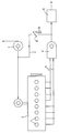
- Intake air drawn in via an air filter is fed to a compressor 1, from which the charge air is fed to the engine 2.
- the exhaust gases from the individual cylinders 3 of the engine 2 are fed via exhaust gas lines 4 to an exhaust gas turbine 5, which drives the compressor 1.
- the exhaust gas turbine 5 is connected on the outlet side to a catalytic converter 6, from which the exhaust gases are released.
- a discharge line 7 branches off, which contains a butterfly valve 8 and is connected to the outlet side of the exhaust gas turbine 5.
- the butterfly valve 8 is adjustable via a pneumatic switch cylinder 9 between an open (gas operation) and a closed (diesel operation) position.
Landscapes
- Engineering & Computer Science (AREA)
- Chemical & Material Sciences (AREA)
- Combustion & Propulsion (AREA)
- Mechanical Engineering (AREA)
- General Engineering & Computer Science (AREA)
- Chemical Kinetics & Catalysis (AREA)
- Health & Medical Sciences (AREA)
- Toxicology (AREA)
- Oil, Petroleum & Natural Gas (AREA)
- Supercharger (AREA)
- Exhaust Gas After Treatment (AREA)
- Valve Device For Special Equipments (AREA)
- Cylinder Crankcases Of Internal Combustion Engines (AREA)
Description
- Die Erfindung betrifft eine mehrzylindrige, insbesondere stationäre Hubkolbenbrennkraftmaschine nach dem Oberbegriff des Patentanspruchs.
- In der gattungsbildenden FR-A- 1330 022 ist eine Hubkolbenbrennkraftmaschine beschrieben, die in erster Linie als Stationärmotor eingesetzt wird. Derartige Motoren unterliegen im stationären Einsatz der Technischen Anleitung Luft mit ihren strengen Emissionsauflagen.
- Aufgabe der Erfindung ist es daher, eine Hubkolbenbrennkraftmaschine nach dem Oberbegriff des Patentanspruchs zu schaffen, bei der in einfacher Weise eine Überschreitung der Schadstoffgrenzwerte der abgegebenen Abgase vermieden wird.
- Die bei derartigen Motoren zur Einhaltung der TA-Luft notwendigen selektiv-katalytisch-reduzierenden [SCR]-Katalysatoren besitzen einen zulässigen Eingangstemperaturbereich, der beispielsweise von 380 bis 500°C reichen kann. Da die Abgastemperatur nach der Abgasturbine im Gasbetrieb bei Vollast im Bereich der oberen Grenze des für den Katalysator zulässigen Temperaturbereichs, in dem Schadstoffgrenzwerte in den abgegebenen Abgasen garantiert werden, liegt, kann nicht unbedingt das Arbeiten im zulässigen Eingangstemperaturbereich des Katalysators gewährleistet werden. Zwar läßt sich die Abgastemperatur durch einen Zwischenkühler zwischen Motor und Katalysator senken, Jedoch ist der damit verbundene Bau- und Regelaufwand relativ groß.
- Im Dieselbetrieb wird keine Luft abgeblasen, da man hierbei ein höheres Verbrennungsluftverhältnis bzw. höheren Ladedruck benötigt, wobei die Grenze nach unten in erster Linie durch die Abgastrübung gegeben ist. Da im Dieselbetrieb im Vergleich zum Gasbetrieb die Abgastemperatur geringer ist, wird hierbei ein Arbeiten im zulässigen Eingangstemperaturbereich des Katalysators von vornherein sichergestellt.
- Im Gegensatz zum Dieselbetrieb erzielt man im Gasbetrieb mit einem kleinen Verbrennungsluftverhältnis eine günstige Verbrennung des Gas-Luftgemisches, weshalb der Ladedruck im Gasbetrieb wegen des geringeren Luftbedarfs vermindert werden muß. Dies geschieht durch Abblasen der zuviel geförderten Luft über eine einstellbare Abblaseklappe, die im Dieselbetrieb geschlossen und im Gasbetrieb durch ein entsprechendes Stellglied, beispielsweise einen Pneumatikzylinder, geöffnet wird.
- Dadurch, daß die beim Gasbetrieb abgeblasene Luft dem Abgasstrom hinter der Abgasturbine zugeleitet wird, statt sie in den Maschinenraum abzublasen, erfolgt eine Absenkung der Abgastemperatur hinter der Turbine. Die noramlerweise beim Gasbetrieb abgeblasene Luftmenge beträgt etwa 4,5 % der Gesamtluftmenge (bei Vollast), wobei die Temperatur der Luft bei etwa 40°C liegt. Bei einer Abgastemperatur von ca. 490° bis 500°C ergibt sich damit eine Temperaturabsenkung des Abgases um ca. 20°C, so daß die Einhaltung der Schadstoffgrenzwerte am Katalysatoraustritt garantiert werden kann. Die notwendigen Installationskosten sind minimal, zumal Schalldämpfer für die bisher in den Raum abgeblasene Luft entfallen und der Installationsaufwand äußerst gering ist.
- Selbst bei 25% Last wird die für den Katalysator minimal zulässige Abgastemperatur von ca. 380°C durch diese Maßnahme nicht unterschritten. Die Erfindung wird nachstehend im Zusammenhang mit einem in der beigefügten Abbildung schematisch dargestellten Ausführungsbeispiel näher erläutert.
- Über ein Luftfilter angesaugte Ansaugluft wird einem Verdichter 1 zugeführt, von dem die Ladeluft dem Motor 2 zugeführt wird. Die Abgase von den einzelnen Zylindern 3 des Motors 2 werden über Abgasleitungen 4 einer Abgasturbine 5 zugeführt, die den Verdichter 1 antreibt. Die Abgasturbine 5 ist austrittsseitig mit einem Katalysator 6 verbunden, von dem die Abgase abgegeben werden.
- Austrittsseitig bezüglich des Verdichters 1 zweigt eine Abführleitung 7 ab, die eine Absperrklappe 8 enthält und mit der Austrittsseite der Abgasturbine 5 verbunden ist. Die Absperrklappe 8 ist über einen pneumatischen Umschaltzylinder 9 zwischen einer geöffneten (Gasbetrieb) und einer geschlossenen (Dieselbetrieb) Stellung verstellbar. Hierdurch wird die beim Gasbetrieb überschüssige Ladeluft durch die beim Gasbetrieb geöffnete Absperrklappe 8 dem die Abgasturbine 5 verlassenden Abgas zugemischt, wodurch dessen Temperatur entsprechend gesenkt wird, so daß ein Arbeiten im zulässigen Eingangstemperaturbereich des Katalysators 6 sichergestellt wird.
Claims (1)
- Im Diesel- und Gasbetrieb betreibbare, mehrzylindrige, vorzugsweise stationäre Hubkolbenbrennkraftmaschine mit einem von einer Abgasturbine (5) betriebenen Verdichter (1) für Ladeluft, und mit einer von der Austrittsseite des Verdichters (1) ausgehenden Abführleitung (7) die eine Absperrklappe (8) aufweist, dadurch gekennzeichnet, daß die Hubkolbenbrennkraftmaschine einen der Abgasturbine (5) nachgeschalteten Katalysator (6) aufweist, der als selektiv-katalytisch-reduzierender (SCR) Katalysator ausgebildet ist, daß die Abführleitung (7) für die Ladeluft dient und hinter der Abgasturbine (5) und vor dem Katalysator (6) in eine Verbindungsleitung zwischen der Abgasturbine (5) und dem Katalysator (6) mündet und daß die Absperrklappe (8) im Dieselbetrieb geschlossen und im Gasbetrieb geöffnet ist.
Priority Applications (1)
| Application Number | Priority Date | Filing Date | Title |
|---|---|---|---|
| AT90122612T ATE98744T1 (de) | 1989-12-01 | 1990-11-27 | Hubkolbenbrennkraftmaschine. |
Applications Claiming Priority (2)
| Application Number | Priority Date | Filing Date | Title |
|---|---|---|---|
| DE3939729A DE3939729A1 (de) | 1989-12-01 | 1989-12-01 | Hubkolbenbrennkraftmaschine |
| DE3939729 | 1989-12-01 |
Publications (2)
| Publication Number | Publication Date |
|---|---|
| EP0430153A1 EP0430153A1 (de) | 1991-06-05 |
| EP0430153B1 true EP0430153B1 (de) | 1993-12-15 |
Family
ID=6394573
Family Applications (1)
| Application Number | Title | Priority Date | Filing Date |
|---|---|---|---|
| EP90122612A Expired - Lifetime EP0430153B1 (de) | 1989-12-01 | 1990-11-27 | Hubkolbenbrennkraftmaschine |
Country Status (3)
| Country | Link |
|---|---|
| EP (1) | EP0430153B1 (de) |
| AT (1) | ATE98744T1 (de) |
| DE (2) | DE3939729A1 (de) |
Families Citing this family (2)
| Publication number | Priority date | Publication date | Assignee | Title |
|---|---|---|---|---|
| DE10062391A1 (de) * | 2000-12-14 | 2002-06-20 | Opel Adam Ag | Mit verschiedenen Kraftstoffen wahlweise betreibbare Brennkraftmaschine, insbesondere für einen Kraftfahrzeugantrieb |
| DE102005005958A1 (de) * | 2005-02-10 | 2006-08-17 | Volkswagen Ag | Brennkraftmaschine mit Gasbetrieb |
Citations (1)
| Publication number | Priority date | Publication date | Assignee | Title |
|---|---|---|---|---|
| US4702219A (en) * | 1984-08-29 | 1987-10-27 | Mazda Motor Corporation | Supercharged engine |
Family Cites Families (6)
| Publication number | Priority date | Publication date | Assignee | Title |
|---|---|---|---|---|
| FR1330022A (fr) * | 1962-07-30 | 1963-06-14 | Motoren Werke Mannheim Ag | Procédé et dispositif pour le réglage d'un moteur à gaz chargé |
| US4122673A (en) * | 1973-09-28 | 1978-10-31 | J. Eberspacher | Internal combustion engine with afterburning and catalytic reaction in a supercharger turbine casing |
| DE2348866A1 (de) * | 1973-09-28 | 1975-04-10 | Eberspaecher J | Verfahren zur reinigung der abgase von mit fluessigem brennstoff betriebenen motoren und einrichtung zur durchfuehrung des verfahrens |
| DE2401204A1 (de) * | 1974-01-11 | 1975-07-17 | Marquardt Peter | Katalytischer abgasreaktor fuer verbrennungsmotoren |
| HU175035B (hu) * | 1977-02-14 | 1980-05-28 | Autoipari Kutato Intezet | Sposob turbokompressornogo zapolnenija dvigatelja vnutrennego sgoranija, rabotajuhhego pri vysokogornykh uslovijakh, a tak zhe takoj dvigatel' dlja osuhhestvlenija sposoba |
| FR2483515A1 (fr) * | 1980-05-27 | 1981-12-04 | Renault | Dispositif antipollution pour moteur a combustion interne a turbocompresseur |
-
1989
- 1989-12-01 DE DE3939729A patent/DE3939729A1/de not_active Withdrawn
-
1990
- 1990-11-27 AT AT90122612T patent/ATE98744T1/de not_active IP Right Cessation
- 1990-11-27 DE DE90122612T patent/DE59003883D1/de not_active Expired - Fee Related
- 1990-11-27 EP EP90122612A patent/EP0430153B1/de not_active Expired - Lifetime
Patent Citations (1)
| Publication number | Priority date | Publication date | Assignee | Title |
|---|---|---|---|---|
| US4702219A (en) * | 1984-08-29 | 1987-10-27 | Mazda Motor Corporation | Supercharged engine |
Also Published As
| Publication number | Publication date |
|---|---|
| ATE98744T1 (de) | 1994-01-15 |
| EP0430153A1 (de) | 1991-06-05 |
| DE59003883D1 (de) | 1994-01-27 |
| DE3939729A1 (de) | 1991-06-06 |
Similar Documents
| Publication | Publication Date | Title |
|---|---|---|
| DE602005000777T2 (de) | Brennkraftmaschine | |
| DE10112521B4 (de) | Dieselmotor | |
| DE4240239C2 (de) | Verbrennungskraftmaschine | |
| EP0885352B1 (de) | Otto-motor mit druckwellenlader | |
| EP0620365B1 (de) | Brennkraftmaschine mit Abgasrückführung | |
| EP2183471B1 (de) | Abgasnachbehandlung vor einem turbolader | |
| DE10035375A1 (de) | Abgasrückzirkulationssystem | |
| DE102004027593A1 (de) | Motorenanlage mit Abgasturboaufladung und Betrieb eines SCR-Katalysators | |
| EP1138927A2 (de) | Turboaufgeladene Brennkraftmaschine mit Abgasrückführung | |
| DE10204482A1 (de) | Brennkraftmaschine | |
| DE112009000423T5 (de) | Verbesserungen bei der Emissionskontrolle | |
| DE10151196A1 (de) | Abgasrückzirkulationssystem in einem Verbrennungsmotor | |
| EP1639245A1 (de) | Brennkraftmaschine mit einem verdichter im ansaugtrakt und verfahren hierzu | |
| DE19833619A1 (de) | Abgasanlage für aufgeladene Brennkraftmaschinen | |
| EP1866535B1 (de) | Verfahren zum betrieb einer brennkraftmaschine und brennkraftmaschine hierzu | |
| DE4443133A1 (de) | Abgasnachbehandlungssystem eines ladedruckbetriebenen Verbrennungsmotors mit Partikelfilter und Brenner | |
| EP1836381A1 (de) | Brennkraftmaschine mit einem den zylindern zugeordneten gasdruckbehälter und verfahren zum betrieb der brennkraftmaschine | |
| EP0430153B1 (de) | Hubkolbenbrennkraftmaschine | |
| DE102007028493A1 (de) | Brennkraftmaschine mit zweistufiger Turboaufladung und Oxidationskatalysator | |
| DE102021205170A1 (de) | Brennkraftmaschine mit einer stromab eines Frischgasverdichters abzweigenden Sekundärluftleitung | |
| DE102015200045A1 (de) | Verfahren zum optimierten Betreiben einer Brennkraftmaschine und Brennkraftmaschine zur Durchführung eines derartigen Verfahrens | |
| DE102018005457A1 (de) | Verfahren zum Betrieb einer Brennkraftmaschine, insbesondere eines Kraftfahrzeugs, in einem Motorbremsbetrieb | |
| DE102009051028A1 (de) | Antriebsaggregat sowie Verfahren zum Betreiben eines Antriebsaggregats | |
| DE102019113736A1 (de) | Brennkraftmaschine mit variabler Auslassventilbetätigung und mit elektrischer Heizvorrichtung im Abgasstrang | |
| DE102019113741A1 (de) | Brennkraftmaschine mit variabler Auslassventilbetätigung und mit elektromotorischer oder mechanischer Aufladung |
Legal Events
| Date | Code | Title | Description |
|---|---|---|---|
| PUAI | Public reference made under article 153(3) epc to a published international application that has entered the european phase |
Free format text: ORIGINAL CODE: 0009012 |
|
| AK | Designated contracting states |
Kind code of ref document: A1 Designated state(s): AT BE DE FR GB LU NL |
|
| 17P | Request for examination filed |
Effective date: 19901127 |
|
| R17P | Request for examination filed (corrected) |
Effective date: 19910521 |
|
| 17Q | First examination report despatched |
Effective date: 19920708 |
|
| GRAA | (expected) grant |
Free format text: ORIGINAL CODE: 0009210 |
|
| AK | Designated contracting states |
Kind code of ref document: B1 Designated state(s): AT BE DE FR GB LU NL |
|
| PG25 | Lapsed in a contracting state [announced via postgrant information from national office to epo] |
Ref country code: NL Effective date: 19931215 Ref country code: BE Effective date: 19931215 |
|
| REF | Corresponds to: |
Ref document number: 98744 Country of ref document: AT Date of ref document: 19940115 Kind code of ref document: T |
|
| GBT | Gb: translation of ep patent filed (gb section 77(6)(a)/1977) |
Effective date: 19931220 |
|
| REF | Corresponds to: |
Ref document number: 59003883 Country of ref document: DE Date of ref document: 19940127 |
|
| ET | Fr: translation filed | ||
| NLV1 | Nl: lapsed or annulled due to failure to fulfill the requirements of art. 29p and 29m of the patents act | ||
| PLBE | No opposition filed within time limit |
Free format text: ORIGINAL CODE: 0009261 |
|
| STAA | Information on the status of an ep patent application or granted ep patent |
Free format text: STATUS: NO OPPOSITION FILED WITHIN TIME LIMIT |
|
| PG25 | Lapsed in a contracting state [announced via postgrant information from national office to epo] |
Ref country code: LU Free format text: LAPSE BECAUSE OF NON-PAYMENT OF DUE FEES Effective date: 19941130 |
|
| 26N | No opposition filed | ||
| PGFP | Annual fee paid to national office [announced via postgrant information from national office to epo] |
Ref country code: FR Payment date: 19951009 Year of fee payment: 6 |
|
| PGFP | Annual fee paid to national office [announced via postgrant information from national office to epo] |
Ref country code: AT Payment date: 19951012 Year of fee payment: 6 |
|
| PGFP | Annual fee paid to national office [announced via postgrant information from national office to epo] |
Ref country code: GB Payment date: 19951017 Year of fee payment: 6 |
|
| PGFP | Annual fee paid to national office [announced via postgrant information from national office to epo] |
Ref country code: DE Payment date: 19951209 Year of fee payment: 6 |
|
| PG25 | Lapsed in a contracting state [announced via postgrant information from national office to epo] |
Ref country code: GB Effective date: 19961127 Ref country code: AT Effective date: 19961127 |
|
| GBPC | Gb: european patent ceased through non-payment of renewal fee |
Effective date: 19961127 |
|
| PG25 | Lapsed in a contracting state [announced via postgrant information from national office to epo] |
Ref country code: FR Effective date: 19970731 |
|
| PG25 | Lapsed in a contracting state [announced via postgrant information from national office to epo] |
Ref country code: DE Effective date: 19970801 |
|
| REG | Reference to a national code |
Ref country code: FR Ref legal event code: ST |