EP0430159A1 - Seringue d'injection de securité à usage unique - Google Patents
Seringue d'injection de securité à usage unique Download PDFInfo
- Publication number
- EP0430159A1 EP0430159A1 EP90122638A EP90122638A EP0430159A1 EP 0430159 A1 EP0430159 A1 EP 0430159A1 EP 90122638 A EP90122638 A EP 90122638A EP 90122638 A EP90122638 A EP 90122638A EP 0430159 A1 EP0430159 A1 EP 0430159A1
- Authority
- EP
- European Patent Office
- Prior art keywords
- cannula
- syringe
- disposable safety
- plunger
- safety syringe
- Prior art date
- Legal status (The legal status is an assumption and is not a legal conclusion. Google has not performed a legal analysis and makes no representation as to the accuracy of the status listed.)
- Granted
Links
- 238000002347 injection Methods 0.000 title description 10
- 239000007924 injection Substances 0.000 title description 10
- 238000004519 manufacturing process Methods 0.000 abstract description 2
- 230000001681 protective effect Effects 0.000 description 5
- 241001631457 Cannula Species 0.000 description 3
- 238000003780 insertion Methods 0.000 description 3
- 230000037431 insertion Effects 0.000 description 3
- 208000027418 Wounds and injury Diseases 0.000 description 2
- 230000006378 damage Effects 0.000 description 2
- 238000011161 development Methods 0.000 description 2
- 230000018109 developmental process Effects 0.000 description 2
- 208000014674 injury Diseases 0.000 description 2
- 238000013459 approach Methods 0.000 description 1
- 238000010276 construction Methods 0.000 description 1
- 230000001419 dependent effect Effects 0.000 description 1
- 238000013461 design Methods 0.000 description 1
- 238000000034 method Methods 0.000 description 1
- 244000052769 pathogen Species 0.000 description 1
- 239000000243 solution Substances 0.000 description 1
- 238000005507 spraying Methods 0.000 description 1
- 238000012549 training Methods 0.000 description 1
- 239000002699 waste material Substances 0.000 description 1
Images


Classifications
-
- A—HUMAN NECESSITIES
- A61—MEDICAL OR VETERINARY SCIENCE; HYGIENE
- A61M—DEVICES FOR INTRODUCING MEDIA INTO, OR ONTO, THE BODY; DEVICES FOR TRANSDUCING BODY MEDIA OR FOR TAKING MEDIA FROM THE BODY; DEVICES FOR PRODUCING OR ENDING SLEEP OR STUPOR
- A61M5/00—Devices for bringing media into the body in a subcutaneous, intra-vascular or intramuscular way; Accessories therefor, e.g. filling or cleaning devices, arm-rests
- A61M5/178—Syringes
- A61M5/31—Details
- A61M5/32—Needles; Details of needles pertaining to their connection with syringe or hub; Accessories for bringing the needle into, or holding the needle on, the body; Devices for protection of needles
- A61M5/3205—Apparatus for removing or disposing of used needles or syringes, e.g. containers; Means for protection against accidental injuries from used needles
- A61M5/321—Means for protection against accidental injuries by used needles
- A61M5/322—Retractable needles, i.e. disconnected from and withdrawn into the syringe barrel by the piston
- A61M5/3221—Constructional features thereof, e.g. to improve manipulation or functioning
- A61M2005/3231—Proximal end of needle captured or embedded inside piston head, e.g. by friction or hooks
-
- A—HUMAN NECESSITIES
- A61—MEDICAL OR VETERINARY SCIENCE; HYGIENE
- A61M—DEVICES FOR INTRODUCING MEDIA INTO, OR ONTO, THE BODY; DEVICES FOR TRANSDUCING BODY MEDIA OR FOR TAKING MEDIA FROM THE BODY; DEVICES FOR PRODUCING OR ENDING SLEEP OR STUPOR
- A61M5/00—Devices for bringing media into the body in a subcutaneous, intra-vascular or intramuscular way; Accessories therefor, e.g. filling or cleaning devices, arm-rests
- A61M5/178—Syringes
- A61M5/31—Details
- A61M5/32—Needles; Details of needles pertaining to their connection with syringe or hub; Accessories for bringing the needle into, or holding the needle on, the body; Devices for protection of needles
- A61M5/34—Constructions for connecting the needle, e.g. to syringe nozzle or needle hub
- A61M2005/342—Off-center needles, i.e. needle connections not being coaxial with the longitudinal symmetry axis of syringe barrel
Definitions
- the invention relates to a safety disposable injection syringe according to the preamble of claim 1.
- cannulas for medical syringes and puncture devices are provided with a cone that allows them to be attached to the syringe.
- a medical syringe In order to guarantee that a medical syringe is largely sterile, non-reusable, so-called disposable syringes are increasingly being used.
- the parts are delivered separately packed.
- the cannula is arranged in a sleeve-shaped protective quiver which is adapted to its shape.
- the cannula is pulled out and its cone is placed on a plug-in attachment of the cylindrical syringe body. After use, the cannula is either pushed back into the protective sleeve or thrown away without a protective sleeve.
- Threading into the protective sleeve requires a moment of attention, a steady hand, a good eye and correct lighting. If this is insufficient, the insertion opening is often missed. This can easily lead to a stab injury with the risk of transmitting pathogens.
- many cannulas are therefore also used without a protective sleeve Thrown waste.
- the syringe as well as the cannula could still be used by people who were not suitable for it, even with the most careful disposal.
- the object of the present invention is to improve a disposable safety injection syringe of the type mentioned at the outset in such a way that manufacture and handling become easier and handling and disposal are safer without having to change the usual dimensions.
- the safety disposable injection syringe according to the invention has a relatively simple construction and is therefore easy to produce at low cost.
- the design according to the invention enables a completely uncomplicated and completely safe retraction of the cannula and thus safe disposal after use of the injection syringe.
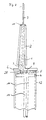
- the drawing shows a safety disposable injection syringe with a cannula 3 having a conical cannula holder 2, a syringe barrel 12, in which a syringe plunger 4 is displaceably arranged.
- the syringe barrel 12 has a conical plug-in attachment 1 for the cannula holder 2 of the cannula 3.
- the cannula 3 projects into the interior of the syringe barrel 12 through the plug-in attachment 1.
- the cannula 3 has a driver 7, for example in the form of a Ring flange or in the form of two diametrically opposite approaches.
- the syringe plunger is provided with a plunger rod 13 which is equipped with a predetermined breaking point 10.
- the syringe plunger 4 has a disk-shaped attachment 5, which can have a smaller diameter than the plunger 4 and in which a receiving device 6, 9 is formed for receiving the driver 7 of the cannula 3 in the foremost inserted position of the syringe plunger 4, as shown in FIG 2 is shown.
- the driver can be chamfered for easier insertion, cf. 1-4.
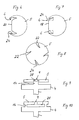
- the receiving device is designed in the form of an undercut slot 6, so that when the syringe plunger 4 rotates, the driver 7 engages behind the undercut 28 of the slot, such that when the syringe plunger 4 is subsequently withdrawn, the cannula 3 is drawn into the syringe barrel 12, as is the case with this is shown in Fig. 3.
- the disk-shaped attachment 5 is arranged at a distance from the syringe plunger 4 by means of a central web 14 or more annular webs 16, cf. 9 and 10.
- the drawing shows a cannula 3 arranged eccentrically to the axis of the syringe barrel 12.
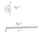
- the slots 6 are located in an edge recess of the disk-shaped attachment 5, as shown in FIGS. 6 to 8.
- the edge recess can be a circular section 18 or a rectangular recess 20, cf. 7 and FIG. 8.
- Several wedge-shaped edge recesses 22 can also be provided, as shown in FIG. 8.
- the slots 6 are preferably located in the lateral region of the recesses 18 and 20. They are preferably of an arcuate shape and taper wedge-shaped. The slots are also preferably provided with a slot wall 24 designed as an inlet flank for the cannula 3.
- the cannula can also be arranged centrally, that is to say aligned with the axis of the syringe barrel 12.
- the slot 9 with undercut 28 is formed in the center of the disc-shaped attachment 5, as shown in FIGS. 9 and 10.
- the cannula 3 is detachably connected to the cannula holder 2 at the end of the cannula holder 2 facing the cannula tip via a sleeve 11 provided with a tear thread, cf. 1 and 2.
- the plunger When the syringe is pulled up, the plunger is first pushed forward and then pulled back, which fills the syringe barrel. The actual spraying process then takes place, the syringe plunger 4 being pushed forward with the aid of the piston rod 13. In the foremost position, the disk-shaped attachment 5 is pushed over the driver 7 of the cannula 3. If the syringe plunger 4 is now rotated, the driver 7 is pushed into the slot 6, cf. 2 in connection with FIGS. 6 to 8. The driver engages behind the undercut of the slot 6.
- the cannula 3 is detached from the cuff 11 and thus from the cannula holder 2 by removing the tear thread.
- the plunger can now be withdrawn and pulls the cannula into the interior of the syringe barrel 12, cf. Fig. 3.
- the piston rod 13 protruding from the syringe cylinder is broken off at the predetermined breaking point 10, so that it is impossible to use the injection syringe again.
Landscapes
- Health & Medical Sciences (AREA)
- Engineering & Computer Science (AREA)
- Heart & Thoracic Surgery (AREA)
- Vascular Medicine (AREA)
- Anesthesiology (AREA)
- Biomedical Technology (AREA)
- Environmental & Geological Engineering (AREA)
- Hematology (AREA)
- Life Sciences & Earth Sciences (AREA)
- Animal Behavior & Ethology (AREA)
- General Health & Medical Sciences (AREA)
- Public Health (AREA)
- Veterinary Medicine (AREA)
- Infusion, Injection, And Reservoir Apparatuses (AREA)
Priority Applications (1)
| Application Number | Priority Date | Filing Date | Title |
|---|---|---|---|
| AT90122638T ATE102489T1 (de) | 1989-11-28 | 1990-11-27 | Sicherheitseinweg-injektionsspritze. |
Applications Claiming Priority (2)
| Application Number | Priority Date | Filing Date | Title |
|---|---|---|---|
| DE3939201A DE3939201A1 (de) | 1989-11-28 | 1989-11-28 | Sicherheits - spritze |
| DE3939201 | 1989-11-28 |
Publications (2)
| Publication Number | Publication Date |
|---|---|
| EP0430159A1 true EP0430159A1 (fr) | 1991-06-05 |
| EP0430159B1 EP0430159B1 (fr) | 1994-03-09 |
Family
ID=6394286
Family Applications (1)
| Application Number | Title | Priority Date | Filing Date |
|---|---|---|---|
| EP90122638A Expired - Lifetime EP0430159B1 (fr) | 1989-11-28 | 1990-11-27 | Seringue d'injection de securité à usage unique |
Country Status (3)
| Country | Link |
|---|---|
| EP (1) | EP0430159B1 (fr) |
| AT (1) | ATE102489T1 (fr) |
| DE (2) | DE3939201A1 (fr) |
Cited By (2)
| Publication number | Priority date | Publication date | Assignee | Title |
|---|---|---|---|---|
| WO1997020586A3 (fr) * | 1995-12-02 | 1997-08-14 | Epsom Glass Ind Ltd | Seringue |
| CN114340712A (zh) * | 2019-07-08 | 2022-04-12 | 贝朗梅尔松根股份公司 | 用于锐利医疗装置的混合式安全弹簧夹及相关方法 |
Families Citing this family (2)
| Publication number | Priority date | Publication date | Assignee | Title |
|---|---|---|---|---|
| DE19645514C2 (de) | 1996-11-05 | 2000-04-13 | Sarstedt Ag & Co | Verfahren und Vorrichtung zum Entsorgen der Kanüle einer Blutentnahmevorrichtung |
| JP3031338B2 (ja) * | 1998-07-14 | 2000-04-10 | 文能 劉 | 多用途安全自動輸液静脈カテーテル |
Citations (4)
| Publication number | Priority date | Publication date | Assignee | Title |
|---|---|---|---|---|
| WO1988008315A1 (fr) * | 1987-04-22 | 1988-11-03 | Maxwell Edmund Whisson | Dispositif parenteral |
| EP0321903A2 (fr) * | 1987-12-21 | 1989-06-28 | Stuart M. Dolgin | Dispositif de passage d'un fluide avec moyen de protection |
| DE3805567A1 (de) * | 1988-02-23 | 1989-08-31 | W Wayne Gloyer | Nicht stechende, vor ansteckung schuetzende sicherheitseinweginjektionsspritze |
| US4932939A (en) * | 1989-03-06 | 1990-06-12 | Magre George R | Safety syringe |
Family Cites Families (2)
| Publication number | Priority date | Publication date | Assignee | Title |
|---|---|---|---|---|
| DE8529315U1 (de) * | 1985-10-11 | 1986-04-17 | PHYSIONIC Gesellschaft für Medizin- und Systemtechnik mbH, 1000 Berlin | Medizinische und/oder technische Injektionsspritze mit Einzugsmechanismus der Injektionskanüle in den Spritzenzylinder |
| US4838870A (en) * | 1987-06-08 | 1989-06-13 | Sherwood Medical Co. | Removable needle attachment having a detachable needle |
-
1989
- 1989-11-28 DE DE3939201A patent/DE3939201A1/de active Granted
-
1990
- 1990-11-27 AT AT90122638T patent/ATE102489T1/de active
- 1990-11-27 EP EP90122638A patent/EP0430159B1/fr not_active Expired - Lifetime
- 1990-11-27 DE DE90122638T patent/DE59004898D1/de not_active Expired - Fee Related
Patent Citations (4)
| Publication number | Priority date | Publication date | Assignee | Title |
|---|---|---|---|---|
| WO1988008315A1 (fr) * | 1987-04-22 | 1988-11-03 | Maxwell Edmund Whisson | Dispositif parenteral |
| EP0321903A2 (fr) * | 1987-12-21 | 1989-06-28 | Stuart M. Dolgin | Dispositif de passage d'un fluide avec moyen de protection |
| DE3805567A1 (de) * | 1988-02-23 | 1989-08-31 | W Wayne Gloyer | Nicht stechende, vor ansteckung schuetzende sicherheitseinweginjektionsspritze |
| US4932939A (en) * | 1989-03-06 | 1990-06-12 | Magre George R | Safety syringe |
Cited By (2)
| Publication number | Priority date | Publication date | Assignee | Title |
|---|---|---|---|---|
| WO1997020586A3 (fr) * | 1995-12-02 | 1997-08-14 | Epsom Glass Ind Ltd | Seringue |
| CN114340712A (zh) * | 2019-07-08 | 2022-04-12 | 贝朗梅尔松根股份公司 | 用于锐利医疗装置的混合式安全弹簧夹及相关方法 |
Also Published As
| Publication number | Publication date |
|---|---|
| DE3939201A1 (de) | 1991-05-29 |
| EP0430159B1 (fr) | 1994-03-09 |
| DE59004898D1 (de) | 1994-04-14 |
| ATE102489T1 (de) | 1994-03-15 |
| DE3939201C2 (fr) | 1992-04-16 |
Similar Documents
| Publication | Publication Date | Title |
|---|---|---|
| EP0287950B1 (fr) | Seringue de sécurite à usage unique | |
| DE102004060146C5 (de) | Autoinjektor mit Arretierung des Wirkstoffbehälters | |
| DE69218592T2 (de) | Spritze | |
| DE102004005435B3 (de) | Medizinisches Transfergerät | |
| EP2401009B1 (fr) | Support de réservoir à produit pour un dispositif d'injection et pour la réception d'un réservoir à produit | |
| DE2857110C1 (de) | Vernichtungseinrichtung fuer Injektionskanuelen | |
| DE69839283T2 (de) | Injektionsvorrichtung | |
| DE10342059B4 (de) | Verabreichungsvorrichtung mit Einstech- und Ausschütteinrichtung | |
| DE69430134T2 (de) | Hypodermische spritze mit zurückziehbarer nadelmontage | |
| DE19510455B4 (de) | Chirurgisches Instrument zum stoßartigen Einführen einer intraossären Trokarnadel | |
| DE3851229T2 (de) | Medizische spritze. | |
| DE69429306T2 (de) | Spritzenaufbau | |
| DE68902781T2 (de) | Sicherheits-wegwerfspritze. | |
| DE69724291T2 (de) | Spritze mit einziehbarer nadelvorrichtung | |
| DE69921704T2 (de) | Nadelunterstützter Strahlinjektor | |
| DE69008850T2 (de) | Spritze mit auswechselbarer und zurückziehbarer kanülenplattform. | |
| DE3871935T2 (de) | Spritze zum einmaligen gebrauch. | |
| WO1999025402A1 (fr) | Configuration d'aiguille | |
| DE3932109A1 (de) | Blutentnahmevorrichtung | |
| DE69603597T2 (de) | Vorgefüllte sicherheitsspritze | |
| DE29912965U1 (de) | Injektionsvorrichtung | |
| EP0314696B1 (fr) | Seringue d'injection avec capuchon protecteur de l'aiguille | |
| DE60120475T2 (de) | Bildungsvorrichtung, insbesondere zum Mischen von Substanzen auf dem Gebiet der Medizin | |
| DE19947998B4 (de) | Injektionsspritze mit Nadelschutz | |
| DE60032171T2 (de) | Verbesserungen bezüglich subkutaninjektionsspritzen |
Legal Events
| Date | Code | Title | Description |
|---|---|---|---|
| PUAI | Public reference made under article 153(3) epc to a published international application that has entered the european phase |
Free format text: ORIGINAL CODE: 0009012 |
|
| AK | Designated contracting states |
Kind code of ref document: A1 Designated state(s): AT BE CH DE DK ES FR GB GR IT LI LU NL SE |
|
| 17P | Request for examination filed |
Effective date: 19910531 |
|
| 17Q | First examination report despatched |
Effective date: 19921106 |
|
| GRAA | (expected) grant |
Free format text: ORIGINAL CODE: 0009210 |
|
| AK | Designated contracting states |
Kind code of ref document: B1 Designated state(s): AT BE CH DE DK ES FR GB GR IT LI LU NL SE |
|
| PG25 | Lapsed in a contracting state [announced via postgrant information from national office to epo] |
Ref country code: GR Free format text: LAPSE BECAUSE OF FAILURE TO SUBMIT A TRANSLATION OF THE DESCRIPTION OR TO PAY THE FEE WITHIN THE PRESCRIBED TIME-LIMIT Effective date: 19940309 Ref country code: ES Free format text: THE PATENT HAS BEEN ANNULLED BY A DECISION OF A NATIONAL AUTHORITY Effective date: 19940309 |
|
| REF | Corresponds to: |
Ref document number: 102489 Country of ref document: AT Date of ref document: 19940315 Kind code of ref document: T |
|
| REF | Corresponds to: |
Ref document number: 59004898 Country of ref document: DE Date of ref document: 19940414 |
|
| ITF | It: translation for a ep patent filed | ||
| GBT | Gb: translation of ep patent filed (gb section 77(6)(a)/1977) |
Effective date: 19940616 |
|
| ET | Fr: translation filed | ||
| PG25 | Lapsed in a contracting state [announced via postgrant information from national office to epo] |
Ref country code: GB Effective date: 19941127 Ref country code: DK Effective date: 19941127 Ref country code: AT Effective date: 19941127 |
|
| PG25 | Lapsed in a contracting state [announced via postgrant information from national office to epo] |
Ref country code: SE Effective date: 19941128 |
|
| PG25 | Lapsed in a contracting state [announced via postgrant information from national office to epo] |
Ref country code: LU Free format text: LAPSE BECAUSE OF NON-PAYMENT OF DUE FEES Effective date: 19941130 Ref country code: LI Effective date: 19941130 Ref country code: CH Effective date: 19941130 Ref country code: BE Effective date: 19941130 |
|
| PLBE | No opposition filed within time limit |
Free format text: ORIGINAL CODE: 0009261 |
|
| STAA | Information on the status of an ep patent application or granted ep patent |
Free format text: STATUS: NO OPPOSITION FILED WITHIN TIME LIMIT |
|
| EAL | Se: european patent in force in sweden |
Ref document number: 90122638.1 |
|
| 26N | No opposition filed | ||
| BERE | Be: lapsed |
Owner name: ODENTHAL JORG CHRISTOPH Effective date: 19941130 |
|
| PG25 | Lapsed in a contracting state [announced via postgrant information from national office to epo] |
Ref country code: NL Effective date: 19950601 |
|
| NLV4 | Nl: lapsed or anulled due to non-payment of the annual fee | ||
| GBPC | Gb: european patent ceased through non-payment of renewal fee |
Effective date: 19941127 |
|
| PG25 | Lapsed in a contracting state [announced via postgrant information from national office to epo] |
Ref country code: FR Effective date: 19950731 |
|
| REG | Reference to a national code |
Ref country code: CH Ref legal event code: PL |
|
| EUG | Se: european patent has lapsed |
Ref document number: 90122638.1 |
|
| REG | Reference to a national code |
Ref country code: FR Ref legal event code: ST |
|
| PGFP | Annual fee paid to national office [announced via postgrant information from national office to epo] |
Ref country code: DE Payment date: 19960731 Year of fee payment: 6 |
|
| PG25 | Lapsed in a contracting state [announced via postgrant information from national office to epo] |
Ref country code: DE Effective date: 19970801 |
|
| PG25 | Lapsed in a contracting state [announced via postgrant information from national office to epo] |
Ref country code: IT Free format text: LAPSE BECAUSE OF NON-PAYMENT OF DUE FEES;WARNING: LAPSES OF ITALIAN PATENTS WITH EFFECTIVE DATE BEFORE 2007 MAY HAVE OCCURRED AT ANY TIME BEFORE 2007. THE CORRECT EFFECTIVE DATE MAY BE DIFFERENT FROM THE ONE RECORDED. Effective date: 20051127 |