EP0430183A2 - Faservorrichtung zur Lichtwellenlängenumwandlung - Google Patents
Faservorrichtung zur Lichtwellenlängenumwandlung Download PDFInfo
- Publication number
- EP0430183A2 EP0430183A2 EP19900122674 EP90122674A EP0430183A2 EP 0430183 A2 EP0430183 A2 EP 0430183A2 EP 19900122674 EP19900122674 EP 19900122674 EP 90122674 A EP90122674 A EP 90122674A EP 0430183 A2 EP0430183 A2 EP 0430183A2
- Authority
- EP
- European Patent Office
- Prior art keywords
- light
- wave
- fiber type
- light wave
- length
- Prior art date
- Legal status (The legal status is an assumption and is not a legal conclusion. Google has not performed a legal analysis and makes no representation as to the accuracy of the status listed.)
- Withdrawn
Links
Images

Classifications
-
- G—PHYSICS
- G11—INFORMATION STORAGE
- G11B—INFORMATION STORAGE BASED ON RELATIVE MOVEMENT BETWEEN RECORD CARRIER AND TRANSDUCER
- G11B7/00—Recording or reproducing by optical means, e.g. recording using a thermal beam of optical radiation by modifying optical properties or the physical structure, reproducing using an optical beam at lower power by sensing optical properties; Record carriers therefor
- G11B7/12—Heads, e.g. forming of the optical beam spot or modulation of the optical beam
- G11B7/135—Means for guiding the beam from the source to the record carrier or from the record carrier to the detector
- G11B7/1398—Means for shaping the cross-section of the beam, e.g. into circular or elliptical cross-section
-
- G—PHYSICS
- G02—OPTICS
- G02B—OPTICAL ELEMENTS, SYSTEMS OR APPARATUS
- G02B5/00—Optical elements other than lenses
- G02B5/001—Axicons, waxicons, reflaxicons
-
- G—PHYSICS
- G02—OPTICS
- G02F—OPTICAL DEVICES OR ARRANGEMENTS FOR THE CONTROL OF LIGHT BY MODIFICATION OF THE OPTICAL PROPERTIES OF THE MEDIA OF THE ELEMENTS INVOLVED THEREIN; NON-LINEAR OPTICS; FREQUENCY-CHANGING OF LIGHT; OPTICAL LOGIC ELEMENTS; OPTICAL ANALOGUE/DIGITAL CONVERTERS
- G02F1/00—Devices or arrangements for the control of the intensity, colour, phase, polarisation or direction of light arriving from an independent light source, e.g. switching, gating or modulating; Non-linear optics
- G02F1/35—Non-linear optics
- G02F1/37—Non-linear optics for second-harmonic generation
- G02F1/377—Non-linear optics for second-harmonic generation in an optical waveguide structure
- G02F1/383—Non-linear optics for second-harmonic generation in an optical waveguide structure of the optical fibre type
-
- G—PHYSICS
- G11—INFORMATION STORAGE
- G11B—INFORMATION STORAGE BASED ON RELATIVE MOVEMENT BETWEEN RECORD CARRIER AND TRANSDUCER
- G11B7/00—Recording or reproducing by optical means, e.g. recording using a thermal beam of optical radiation by modifying optical properties or the physical structure, reproducing using an optical beam at lower power by sensing optical properties; Record carriers therefor
- G11B7/12—Heads, e.g. forming of the optical beam spot or modulation of the optical beam
- G11B7/135—Means for guiding the beam from the source to the record carrier or from the record carrier to the detector
- G11B7/1372—Lenses
- G11B7/1376—Collimator lenses
-
- G—PHYSICS
- G02—OPTICS
- G02F—OPTICAL DEVICES OR ARRANGEMENTS FOR THE CONTROL OF LIGHT BY MODIFICATION OF THE OPTICAL PROPERTIES OF THE MEDIA OF THE ELEMENTS INVOLVED THEREIN; NON-LINEAR OPTICS; FREQUENCY-CHANGING OF LIGHT; OPTICAL LOGIC ELEMENTS; OPTICAL ANALOGUE/DIGITAL CONVERTERS
- G02F1/00—Devices or arrangements for the control of the intensity, colour, phase, polarisation or direction of light arriving from an independent light source, e.g. switching, gating or modulating; Non-linear optics
- G02F1/35—Non-linear optics
- G02F1/37—Non-linear optics for second-harmonic generation
- G02F1/372—Means for homogenizing the output beam
Definitions
- the present invention relates to a light wave-length converting apparatus of fiber type.
- a fiber type SHG (Second Harmonics Generator) using a secondary nonlinear optical effect has been known as a light wave-length converting apparatus.
- the fiber type SHG uses the phase matching of Cerenkov irradiation system. According to such a system, the second harmonic (hereinafter, abbreviated to an SH wave) is generated, to which phase matching is attained almost automatically.
- the emerging SH wave has a ring-like intensity distribution and its equiphase surface is conical.
- an optical system is generally used which comprises a combination of: an axicon lens 3 for converting an SH wave which was emitted from the primary light source 1 and wave-length converted by a fiber type SHG 2 into a parallel light; and a condenser lens 4 for focusing the parallel light derived from the axicon lens 3.
- an optical system as shown in Fig. 2 is conceivable.
- the parallel light from the axicon lens 3 passes through a beam splitter 5 and is transmitted through a quarter wave-length ( ⁇ /4) plate 6. Thereafter, the light is focused onto an information recording surface of an optical disk 8 by an objective lens 7 (corresponding to the condenser lens 4 in Fig. 1). The reflected light from the information recording surface passes through the objective lens 7 and the quarter wave-length plate 6. After that, the light is reflected by the beam splitter 5. The reflected light then passes through a condenser lens 9 and a cylindrical lens 10 and enters into the photo sensitive surface of a photodetector 11.
- the diameter of the light beam must be adjusted so as to sufficiently satisfy conditions determined a numerical aperture (NA) of the objective lens 7. Further, if the objective lens 7 is vibrated in the direction perpendicular to the optical axis by a tracking servo operation, the ring-like light beam would be interrupted by the objective lens 7, so that a drawback will result such that the intensity distribution becomes uneven and a focused light spot is disturbed.
- NA numerical aperture
- the above drawbacks are originated from the fact that the light of the light source has a ring-like intensity distribution.
- an object of the invention to provide a fiber type light wave-length converting apparatus which can obtain an SH wave of a parallel light having a circular intensity distribution.
- a fiber type light wave-length converting apparatus comprises: a fiber type SHG for converting the wave-length of an incident light; an axicon lens for converting the light emitted from the SHG into the parallel light; and a condenser lens for focusing the parallel light from the axicon lens, wherein the axicon lens is arranged at a position which satisfies the condition of
- L D/2tan ⁇ for the SHG when it is assumed that a distance from the emitting end surface of the SHG to the front end of the axicon lens is expressed by L and an outer diameter of the SHG is set to D and a Cerenkov angle is expressed by ⁇ .
- an SH wave of the parallel light having a circular intensity distribution is obtained by the positional relation which satisfies the above condition of the axicon lens for the SHG.
- Fig. 1 is a diagram showing an example of a conventional light wave-length converting apparatus
- Fig. 2 is a diagram showing the construction of an optical system of an optical pickup using the apparatus of Fig. 1 as a light source;
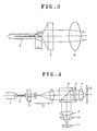
- Fig. 3 is a diagram showing the construction of an embodiment of the invention.
- Fig. 4 is a diagram showing the construction of an optical system of an optical pickup using the apparatus of Fig. 3 as a light source;
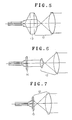
- Figs. 5 to 7 are diagrams showing the construction of other embodiments of the invention.
- a fiber type light wave-length converting apparatus comprises the primary light source 1, fiber type SHG 2, axicon lens 3, and condenser lens 4 in a manner similar to the conventional apparatus shown in Fig. 1.
- the axicon lens 3 is arranged at a position which satisfies the condition of
- L D/2tan ⁇ for the SHG 2 when it is assumed that a distance from the emitting edge surface of the SHG 2 to the front edge of the axicon lens 3 and an outer diameter of the SHG 2 are expressed by L and D respectively, and a Cerenkov angle (SH wave emitting angle) is expressed by ⁇ .
- the SH wave can be utilized efficiently. Therefore, if the fiber type light wave-length converting apparatus of the invention is used as a light source of an optical pickup, as shown in Fig. 4, the optical pickup can be constructed in a manner similar to the conventional optical system.
- the SH wave emitted from the axicon lens 3 is expanded by a beam expander optical system 12 and, thereafter, it enters the beam splitter 5.
- the axicon lens for converting the SH wave emitted from the SHG 2 into the parallel light is not limited to the construction of Fig. 3 but can be also constructed as shown in Fig. 5, 6, or 7. That is, there is a construction using a condenser lens compound type axicon lens 13 (Fig. 5) in which an axicon lens and a condenser lens on the incident side of a beam expander are constructed to an integrated form. There is a construction using a Fresnel type axicon lens 14 (Fig. 6). There is also a construction using a compound lens 15 (Fig.
- an axicon lens and a condenser lens on the incident side of a beam expander are constructed into an integrated form and one surface is formed as a Fresnel type axicon lens and the other surface is formed as a Fresnel type condenser lens.
- an axicon lens having a structure which can convert the SH wave emitted from the SHG 2 into the parallel light or a structure which can convert the SH wave into the parallel light and can focus the parallel light after the conversion.
- the axicon lens is arranged at a position which satisfies the condition of
Landscapes
- Physics & Mathematics (AREA)
- Optics & Photonics (AREA)
- Nonlinear Science (AREA)
- General Physics & Mathematics (AREA)
- Optical Head (AREA)
- Light Guides In General And Applications Therefor (AREA)
- Optical Fibers, Optical Fiber Cores, And Optical Fiber Bundles (AREA)
Applications Claiming Priority (2)
| Application Number | Priority Date | Filing Date | Title |
|---|---|---|---|
| JP306977/89 | 1989-11-27 | ||
| JP1306977A JPH03166531A (ja) | 1989-11-27 | 1989-11-27 | ファイバー型光波長変換装置 |
Publications (2)
| Publication Number | Publication Date |
|---|---|
| EP0430183A2 true EP0430183A2 (de) | 1991-06-05 |
| EP0430183A3 EP0430183A3 (en) | 1992-03-18 |
Family
ID=17963542
Family Applications (1)
| Application Number | Title | Priority Date | Filing Date |
|---|---|---|---|
| EP19900122674 Withdrawn EP0430183A3 (en) | 1989-11-27 | 1990-11-27 | Fiber type light wave-length converting apparatus |
Country Status (3)
| Country | Link |
|---|---|
| US (1) | US5052772A (de) |
| EP (1) | EP0430183A3 (de) |
| JP (1) | JPH03166531A (de) |
Cited By (3)
| Publication number | Priority date | Publication date | Assignee | Title |
|---|---|---|---|---|
| EP0490291A1 (de) * | 1990-12-14 | 1992-06-17 | Sumitomo Electric Industries, Ltd. | Lichtquelleneinrichtung |
| EP0527653A3 (en) * | 1991-08-14 | 1993-10-20 | Pioneer Electronic Corp | Fiber type wavelength converter |
| EP0627643A3 (de) * | 1993-06-03 | 1995-04-12 | Hamamatsu Photonics Kk | Optisches Laser-Abtastsystem mit Axikon. |
Families Citing this family (5)
| Publication number | Priority date | Publication date | Assignee | Title |
|---|---|---|---|---|
| US6281993B1 (en) * | 1998-03-30 | 2001-08-28 | International Business Machines Corporation | Phase shifting element for optical information processing storing systems |
| US8529139B2 (en) | 1998-09-22 | 2013-09-10 | Digitaloptics Corporation East | Optical element and system using the same |
| US6496621B1 (en) * | 1998-09-22 | 2002-12-17 | Digital Optics Corp. | Fiber coupler system and associated methods for reducing back reflections |
| US6961489B2 (en) * | 2003-06-30 | 2005-11-01 | Finisar Corporation | High speed optical system |
| JP6063670B2 (ja) * | 2011-09-16 | 2017-01-18 | 株式会社アマダホールディングス | レーザ切断加工方法及び装置 |
Family Cites Families (4)
| Publication number | Priority date | Publication date | Assignee | Title |
|---|---|---|---|---|
| JPH01287531A (ja) * | 1988-05-14 | 1989-11-20 | Sumitomo Electric Ind Ltd | 光源装置 |
| JPH01293326A (ja) * | 1988-05-20 | 1989-11-27 | Pioneer Electron Corp | ファイバー型光波長変換装置 |
| JP2686536B2 (ja) * | 1988-05-20 | 1997-12-08 | パイオニア株式会社 | ファイバー型光波長変換装置 |
| US4919511A (en) * | 1989-02-03 | 1990-04-24 | Pioneer Electronic Corporation | Fibre-type light conversion device |
-
1989
- 1989-11-27 JP JP1306977A patent/JPH03166531A/ja active Pending
-
1990
- 1990-11-26 US US07/617,817 patent/US5052772A/en not_active Expired - Fee Related
- 1990-11-27 EP EP19900122674 patent/EP0430183A3/en not_active Withdrawn
Cited By (6)
| Publication number | Priority date | Publication date | Assignee | Title |
|---|---|---|---|---|
| EP0490291A1 (de) * | 1990-12-14 | 1992-06-17 | Sumitomo Electric Industries, Ltd. | Lichtquelleneinrichtung |
| US5195159A (en) * | 1990-12-14 | 1993-03-16 | Sumitomo Electric Industries, Ltd. | Optical wavelength converter device |
| EP0527653A3 (en) * | 1991-08-14 | 1993-10-20 | Pioneer Electronic Corp | Fiber type wavelength converter |
| EP0627643A3 (de) * | 1993-06-03 | 1995-04-12 | Hamamatsu Photonics Kk | Optisches Laser-Abtastsystem mit Axikon. |
| US5583342A (en) * | 1993-06-03 | 1996-12-10 | Hamamatsu Photonics K.K. | Laser scanning optical system and laser scanning optical apparatus |
| US5796112A (en) * | 1993-06-03 | 1998-08-18 | Hamamatsu Photonics K.K. | Laser scanning optical system and laser scanning optical apparatus |
Also Published As
| Publication number | Publication date |
|---|---|
| US5052772A (en) | 1991-10-01 |
| EP0430183A3 (en) | 1992-03-18 |
| JPH03166531A (ja) | 1991-07-18 |
Similar Documents
| Publication | Publication Date | Title |
|---|---|---|
| JP2788777B2 (ja) | 光ピックアップ | |
| US5974020A (en) | Two-wavelength laser pick-up head for a DVD | |
| US5822287A (en) | Optical recording method, optical recording apparatus and optical recording medium | |
| US4635244A (en) | Optical beam shaping system | |
| EP0444766A2 (de) | Optischer Abtastkopf, optischer Datenaufzeichnungsträger und Aufzeichnungs-/Wiedergabegerät | |
| KR20010048963A (ko) | 고밀도 광집속을 위한 대물렌즈 및 이를 채용한광픽업장치 및 광디스크 | |
| US5052772A (en) | Fiber type light wave-length converting apparatus | |
| US4235507A (en) | Optical system to condense light from a semiconductor laser into a circular spot | |
| JPH06274931A (ja) | 光ピックアップおよび光ピックアップにおけるビーム整形機能を有するカップリングレンズ | |
| JP2877044B2 (ja) | 光ヘッド装置 | |
| US5737299A (en) | Optical pickup apparatus having wave plates | |
| JP2655065B2 (ja) | 超解像光ヘッド装置 | |
| JPH0291829A (ja) | 光ヘッド装置 | |
| JP2817452B2 (ja) | 光ピックアップ装置 | |
| JP2636245B2 (ja) | 光磁気記憶用光ヘッド | |
| JPH0523411B2 (de) | ||
| JPH03166530A (ja) | ファイバー型光波長変換装置 | |
| JPS6356614B2 (de) | ||
| JPS6256581B2 (de) | ||
| KR100339345B1 (ko) | 광픽업장치 | |
| KR100233115B1 (ko) | 광픽업 장치 | |
| JP2538192B2 (ja) | 光ディスク装置 | |
| KR100195082B1 (ko) | 광헤드 | |
| JPS6182344A (ja) | 光ピツクアツプ | |
| KR100200807B1 (ko) | 초해상의 고밀도 광기록방법 및 이를 이용한 광픽업 |
Legal Events
| Date | Code | Title | Description |
|---|---|---|---|
| PUAI | Public reference made under article 153(3) epc to a published international application that has entered the european phase |
Free format text: ORIGINAL CODE: 0009012 |
|
| AK | Designated contracting states |
Kind code of ref document: A2 Designated state(s): DE FR GB |
|
| RIN1 | Information on inventor provided before grant (corrected) |
Inventor name: OKAMOTO, KIYOFUMI Inventor name: OKAMOTO, SOTA |
|
| RIN1 | Information on inventor provided before grant (corrected) |
Inventor name: OKAMOTO, SOTA Inventor name: CHIKUMA, KIYOFUMI |
|
| PUAL | Search report despatched |
Free format text: ORIGINAL CODE: 0009013 |
|
| AK | Designated contracting states |
Kind code of ref document: A3 Designated state(s): DE FR GB |
|
| 17P | Request for examination filed |
Effective date: 19920527 |
|
| 17Q | First examination report despatched |
Effective date: 19931015 |
|
| STAA | Information on the status of an ep patent application or granted ep patent |
Free format text: STATUS: THE APPLICATION IS DEEMED TO BE WITHDRAWN |
|
| 18D | Application deemed to be withdrawn |
Effective date: 19941011 |