EP0430246B1 - Méthode d'évaluation de signaux d'image couleur - Google Patents
Méthode d'évaluation de signaux d'image couleur Download PDFInfo
- Publication number
- EP0430246B1 EP0430246B1 EP90122863A EP90122863A EP0430246B1 EP 0430246 B1 EP0430246 B1 EP 0430246B1 EP 90122863 A EP90122863 A EP 90122863A EP 90122863 A EP90122863 A EP 90122863A EP 0430246 B1 EP0430246 B1 EP 0430246B1
- Authority
- EP
- European Patent Office
- Prior art keywords
- signal
- differentiated
- value
- color
- vector
- Prior art date
- Legal status (The legal status is an assumption and is not a legal conclusion. Google has not performed a legal analysis and makes no representation as to the accuracy of the status listed.)
- Expired - Lifetime
Links
Images
Classifications
-
- G—PHYSICS
- G06—COMPUTING OR CALCULATING; COUNTING
- G06T—IMAGE DATA PROCESSING OR GENERATION, IN GENERAL
- G06T7/00—Image analysis
- G06T7/0002—Inspection of images, e.g. flaw detection
-
- H—ELECTRICITY
- H04—ELECTRIC COMMUNICATION TECHNIQUE
- H04N—PICTORIAL COMMUNICATION, e.g. TELEVISION
- H04N17/00—Diagnosis, testing or measuring for television systems or their details
- H04N17/02—Diagnosis, testing or measuring for television systems or their details for colour television signals
-
- G—PHYSICS
- G06—COMPUTING OR CALCULATING; COUNTING
- G06T—IMAGE DATA PROCESSING OR GENERATION, IN GENERAL
- G06T7/00—Image analysis
- G06T7/90—Determination of colour characteristics
-
- G—PHYSICS
- G06—COMPUTING OR CALCULATING; COUNTING
- G06T—IMAGE DATA PROCESSING OR GENERATION, IN GENERAL
- G06T2207/00—Indexing scheme for image analysis or image enhancement
- G06T2207/10—Image acquisition modality
- G06T2207/10024—Color image
-
- G—PHYSICS
- G06—COMPUTING OR CALCULATING; COUNTING
- G06T—IMAGE DATA PROCESSING OR GENERATION, IN GENERAL
- G06T2207/00—Indexing scheme for image analysis or image enhancement
- G06T2207/30—Subject of image; Context of image processing
- G06T2207/30168—Image quality inspection
Definitions
- the present invention relates to a method for evaluating color image signals available from, for example, CCD color image sensors fabricated as semiconductor IC's.
- the semiconductor CCD image sensors are produced using the IC technology but they may sometimes be defective from various causes in their manufacturing process.
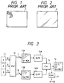
- color reproduction errors such as shading shown in Fig. 1 and stripes of colors shown in Fig. 2 are induced owing to defects of the image sensor itself.
- the shading in Fig. 1 is a color reproduction error that the reproduced picture, which ought to be white, is colored over a wide area (at the upper left in Fig. 1).
- the bands of colors in Fig. 2 are slanted or vertical colored stripes which appear in the reproduced picture which ought to be white.
- color reproduction errors are detected through visual inspection of a display image provided on a CRT display screen by the color image signal output from the color image sensor shed evenly all over its light receiving surface by standard white light.
- the conventional testing of color image sensors thus involves direct visual inspection of the color reproduction errors by test personnel, and hence is inefficient.
- the traditional inspection of color image sensors calls for many test personnel at the mass-production site, in particular; consequently, this goes against labor saving and does not lead to the reduction of manufacturing costs of color image sensors.
- clear-cut color patterns can be detected without any individual difference among test personnel but pale color patterns may sometimes escape particular test personnel's notice.
- Color Quality Inspection of Imaging Device discloses an automated color defect inspection system of color imaging devices.
- the system uses color image processing technology to analyze color images based on signals R-Y and B-Y.
- Color edge detection and color contrast calculation methods are used to detect and evaluate the color defects. More particularly, evaluation using color contrast detects a boundary between two colored regions using a Sobel edge mask on the R-Y and B-Y images.
- a resulting color edge image is thresholded to obtain a binary image showing where strong color defects are. The largest segment from the binary edge image is selected as the most likely defect and the centroid of the segment is calculated.
- a local window is set on the centroid for further processing.
- a scatterplot representing the frequency of a particular hue and saturation on the image is plotted at the color's position in the two dimensional color space (R-Y, B-Y). Color contrast is calculated by analyzing the scatterplot.
- the I and Q signals are each differentiated in the direction of each pixel array and the differentiated I and Q signals are composed with vectors.
- the differentiated vector-composed value thus obtained eliminates the influence of color shading and undergoes a marked change when color variations are locally distributed.
- the differentiated value undergoes a particularly sharp and substantial change. Consequently, by detecting those areas of the display image where the differentiated value is great, it is possible to detect stripes or islands of colors which appear locally in the display image.
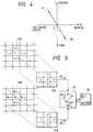
- Reference numeral 11 indicates a color image signal source, which can be formed by a color imaging device employing a solid-state image sensor such as a CCD.
- the signal source 11 is assumed to produce monochromatic signals R, G and B individually, which are applied to a converter 12 for conversion into I and Q signals.
- R, G and B indicate red, green and blue monochromatic signals.
- the luminance signal Y goes to a 1 and the I and Q signals both 0's.
- the I and Q signals are represented by orthogonal coordinates shown in Fig. 4, and a color and its depth are specified at each coordinate position on the orthogonal coordinates.
- the origin S represents white color.
- the Q axis represents purple toward the positive side and yellowish green toward the negative side, whereas the I axis represents orange toward the positive side and cyan toward the negative side.
- the I signal and the Q signal are stored in a first image memory 13A and a second image memory 13B, each having addresses corresponding to pixels on the light receiving surface of an image sensor.
- the original color image signal is split into blocks each composed of, for example, 10 ⁇ 10 pixels, and mean values of data of the I and Q signals are obtained for each block, and the mean values are stored, as pieces of one-pixel data, in the order of addresses. Consequently, the frame size is reduced down to 1/10 in both of the vertical and lateral directions.
- the following description will be given in connection with the case processing the data of such a reduced frame, but it is a matter of course that the original data may be processed without reducing the frame size.
- the pieces of data of the I and Q signals stored in the first and second image memories 13A and 13B are read out therefrom for each same pixel position and differentiated by differentiators 14A and 14B, respectively.
- the differentiated value is the sum total of the results of such multiplications, and consequently, the numeric values written in the differentiators 14A and 14B in Fig.
- dI i,j (4I i,j - I i-l,j - I i+l,j - I i,j-l - I i,j+l )
- dQ i,j (4Q i,j - Q i-l,j - Q i+l,j - Q i,j-l - Q i,j+l )
- the starting pixel position (i, j) is gradually moved in the direction of line scanning and color pixel data over the entire area of the frame (the reduced frame in this case) is differentiated with respect to each direction of pixel array.
- a composite differentiated output is obtained which is composed of differentiated outputs in the vertical and lateral directions.
- the differentiated outputs dI i,j and dQ i,j at each pixel position, differentiated by the differentiators 14A and 14B, respectively, are vector-composed by a calculating part 15.
- the result of calculation by the calculating part 15 is written in a third image memory 16 at an address corresponding to each pixel position (i, j).
- the differentiated vector-composed value written in the third image memory 16 represents the absolute value of the amount of change of the color signal.
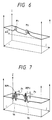
- Fig. 6 is a graph showing an example of the data of the color signal I stored in the first image memory 13A prior to the differentiation.
- the slope ⁇ S in Fig. 6 indicates the influence of color shading, and mountains M 1 and M 2 appearing in the slope ⁇ S indicate stripes of colors.
- Fig. 7 is a graph showing an example of the differentiated vector-composed value Z stored in the third image memory 16.
- the differentiation eliminates the slope ⁇ S resulting from color shading, shown in Fig. 6, and emphasizes the mountains M 1 and M 2 , as indicated by NM 1 and NM 2 .
- the differentiated vector-composed values Z which are stored in the third image memory 16, are free from the influence of color shading but instead a stripe- or island-shaped colored area is emphasized by the differentiating operation. That is, even if a color varies gently, the variation is emphasized by the differentiation before the value Z is input into the third image memory 16,
- An evaluation part 17 sequentially reads out the differentiated vector-composed values Z i,j written in the third image memory 16 and, based on their variations, that is, the heights of peaks P 1 and P 2 , volumes V 1 and V 2 and plane areas A 1 and A 2 of the mountains NM 1 and NM 2 depicted in Fig. 7, determines whether or not the color reproduction errors are within a given limit range, then yields an output of evaluation of the color image signal, i.e. an output indicating whether the signal is good (G) or no good (NG).
- the coefficients k 1 , k 2 and k 3 are constants which are determined experimentally.
- the factor F is compared with a predetermined value, and depending whether the former is smaller or greater than the latter, the detected color reproduction error is determined to fall inside or outside the given limit range.
- the peak parameter P may be, for example, the larger one of the peaks of the mountains NM 1 and NM 2 shown in Fig. 7, or an average value of peak values exceeding a predetermined value, or it may be determined by some other methods.
- the area parameter A may also be, for example, the sum total of those of horizontal cross-sectional areas of the mountains NM 1 and NM 2 at a predetermined height which are in excess of a predetermined value, or a maximum one of such cross-sectional areas, or it may also be determined by some other methods.
- the volume parameter V may also be determined using various methods. As regards that one of the parameters P, A and V which is not used, the value of the corresponding one of the coefficients k 1 , k 2 and k 3 needs only to be reduced to zero.
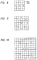
- each pixel data to be subtracted is pixel data at an address apart from the center pixel position by one pixel.
- the differentiation sensitivity and the differentiation characteristic can be adjusted by arbitrarily setting the distance from the center pixel position to the pixel position of the pixel data to be subtracted.
- pixel data may be added to that at the center pixel position as depicted in Fig. 10.
- a differentiation filter of a desired characteristic can be implemented.
Landscapes
- Engineering & Computer Science (AREA)
- Computer Vision & Pattern Recognition (AREA)
- Physics & Mathematics (AREA)
- General Physics & Mathematics (AREA)
- Theoretical Computer Science (AREA)
- Quality & Reliability (AREA)
- Biomedical Technology (AREA)
- General Health & Medical Sciences (AREA)
- Multimedia (AREA)
- Signal Processing (AREA)
- Health & Medical Sciences (AREA)
- Image Analysis (AREA)
- Picture Signal Circuits (AREA)
- Testing, Inspecting, Measuring Of Stereoscopic Televisions And Televisions (AREA)
- Processing Of Color Television Signals (AREA)
Claims (1)
- Procédé d'évaluation d'un signal d'image en couleur dans lequel :(a) un signal d'image en couleur correspondant à chaque position de pixel sur un écran d'affichage est converti en un signal I et un Signal Q;(b) ledit signal I et ledit signal Q sont stockés, en tant que données de pixel, dans des première et seconde mémoires d'image en une adresse correspondant à chaque position de pixel;(c) lesdites données de pixel de signal I et lesdites données de pixel de signal Q sont extraites des adresses correspondantes desdits premiers et seconds moyens de mémoire d'image, respectivement, et sont séquentiellement différentiées par rapport aux directions de tableaux de pixels pour obtenir une valeur différentiée de signal I dI et une valeur différentiée de signal Q dQ correspondant à chaque position de pixel;(d) ladite valeur différentiée de signal I dI et ladite valeur différentiée de signal Q dQ sont composées à partir de vecteurs pour obtenir une valeur différentiée composée de vecteur Z pour chaque position de pixel, ladite valeur différentiée composée de vecteur à ladite position de pixel étant calculée par l'équation suivante :
 (e) ladite valeur différentiée composée de vecteur Z en chaque position de pixel est stockée dans une troisième mémoire d'image à l'adresse correspondante; et(f) la valeur d'une variation de ladite valeur différentiée composée de vecteur Z stockée dans ladite troisième mémoire d'image est calculée comme un coefficient F représentant le degré d'une erreur de reproduction de couleur et ledit coefficient F est comparé à une valeur prédéterminée pour déterminer ainsi si oui ou non ladite erreur de reproduction de couleur se situe à l'intérieur d'une plage limite donnée, dans lequel, les paramètres de sommet, de surface et de volume d'une variation en bosse de ladite valeur différentiée composée de vecteur Z étant représentés par P, A et V, respectivement, ledit coefficient F est défini par l'équation suivante :
Applications Claiming Priority (2)
| Application Number | Priority Date | Filing Date | Title |
|---|---|---|---|
| JP312364/89 | 1989-12-01 | ||
| JP1312364A JP2945423B2 (ja) | 1989-12-01 | 1989-12-01 | カラー画像信号評価方法 |
Publications (3)
| Publication Number | Publication Date |
|---|---|
| EP0430246A2 EP0430246A2 (fr) | 1991-06-05 |
| EP0430246A3 EP0430246A3 (en) | 1992-12-02 |
| EP0430246B1 true EP0430246B1 (fr) | 1997-09-10 |
Family
ID=18028367
Family Applications (1)
| Application Number | Title | Priority Date | Filing Date |
|---|---|---|---|
| EP90122863A Expired - Lifetime EP0430246B1 (fr) | 1989-12-01 | 1990-11-29 | Méthode d'évaluation de signaux d'image couleur |
Country Status (6)
| Country | Link |
|---|---|
| US (1) | US5121199A (fr) |
| EP (1) | EP0430246B1 (fr) |
| JP (1) | JP2945423B2 (fr) |
| KR (1) | KR940000362B1 (fr) |
| CA (1) | CA2030920A1 (fr) |
| DE (1) | DE69031416T2 (fr) |
Families Citing this family (4)
| Publication number | Priority date | Publication date | Assignee | Title |
|---|---|---|---|---|
| DE4002298C2 (de) * | 1990-01-26 | 1995-11-09 | Agfa Gevaert Ag | Verfahren und Vorrichtung zur automatischen Korrektur von Farbstichen bei der elektronischen Bildverarbeitung |
| JP2728789B2 (ja) * | 1991-02-13 | 1998-03-18 | 株式会社東芝 | カラー固体撮像素子の検査装置 |
| IL115026A (en) * | 1995-08-21 | 2001-03-19 | Scitex Corp Ltd | A method for matching object colors to print colors |
| US8760631B2 (en) | 2010-01-27 | 2014-06-24 | Intersil Americas Inc. | Distance sensing by IQ domain differentiation of time of flight (TOF) measurements |
Family Cites Families (6)
| Publication number | Priority date | Publication date | Assignee | Title |
|---|---|---|---|---|
| US3778541A (en) * | 1971-09-03 | 1973-12-11 | Itek Corp | System for analyzing multicolored scenes |
| JPS59223062A (ja) * | 1983-06-01 | 1984-12-14 | Canon Inc | 画像読取装置 |
| US4811047A (en) * | 1983-08-25 | 1989-03-07 | Canon Kabushiki Kaisha | Image forming apparatus with means for recognizing an original condition |
| JPS60124170A (ja) * | 1983-12-09 | 1985-07-03 | Canon Inc | 画像読取り装置 |
| JPS6153868A (ja) * | 1984-08-24 | 1986-03-17 | Dainippon Screen Mfg Co Ltd | 画像走査信号処理におけるキャリブレーション装置 |
| US4839721A (en) * | 1984-08-28 | 1989-06-13 | Polaroid Corporation | Method of and apparatus for transforming color image data on the basis of an isotropic and uniform colorimetric space |
-
1989
- 1989-12-01 JP JP1312364A patent/JP2945423B2/ja not_active Expired - Fee Related
-
1990
- 1990-11-27 CA CA002030920A patent/CA2030920A1/fr not_active Abandoned
- 1990-11-29 EP EP90122863A patent/EP0430246B1/fr not_active Expired - Lifetime
- 1990-11-29 US US07/647,489 patent/US5121199A/en not_active Expired - Fee Related
- 1990-11-29 DE DE69031416T patent/DE69031416T2/de not_active Expired - Fee Related
- 1990-12-01 KR KR1019900019705A patent/KR940000362B1/ko not_active Expired - Fee Related
Also Published As
| Publication number | Publication date |
|---|---|
| EP0430246A3 (en) | 1992-12-02 |
| KR910012747A (ko) | 1991-08-08 |
| JPH03173292A (ja) | 1991-07-26 |
| DE69031416T2 (de) | 1998-02-05 |
| KR940000362B1 (ko) | 1994-01-17 |
| DE69031416D1 (de) | 1997-10-16 |
| JP2945423B2 (ja) | 1999-09-06 |
| EP0430246A2 (fr) | 1991-06-05 |
| US5121199A (en) | 1992-06-09 |
| CA2030920A1 (fr) | 1991-06-02 |
Similar Documents
| Publication | Publication Date | Title |
|---|---|---|
| EP0417633B1 (fr) | Méthode et appareil pour l'évaluation de signaux d'image en couleurs | |
| US5805217A (en) | Method and system for interpolating missing picture elements in a single color component array obtained from a single color sensor | |
| US6724945B1 (en) | Correcting defect pixels in a digital image | |
| US6023334A (en) | Method and apparatus for detecting minute irregularities on the surface of an object | |
| KR100241504B1 (ko) | 표시 스크린 검사 방법 | |
| JP4230880B2 (ja) | 欠陥検査方法 | |
| EP0430246B1 (fr) | Méthode d'évaluation de signaux d'image couleur | |
| US5881164A (en) | Image data processing method and image data processing apparatus | |
| EP0486701B1 (fr) | Procede de detection de lignes | |
| US7668344B2 (en) | Stain inspection method and apparatus | |
| JPH08145907A (ja) | 欠陥検査装置 | |
| JP2001028059A (ja) | 色ムラ検査方法及び装置 | |
| JP4244046B2 (ja) | 画像処理方法および画像処理装置 | |
| JP3015325B2 (ja) | スジキズ検査方法及びその装置 | |
| JPH08327497A (ja) | カラー液晶表示パネルの検査方法 | |
| JP2807031B2 (ja) | カラー画像信号の評価方法及びこの評価方法を用いたカラー画像信号評価装置 | |
| JP2948291B2 (ja) | カラー画像信号の評価装置 | |
| JPH07301609A (ja) | 欠陥検査方法 | |
| JPH07162762A (ja) | しきい値算出装置 | |
| JPH08159984A (ja) | パタンムラ検査装置 | |
| JPH0760135B2 (ja) | ウエハ欠陥検査の画像処理方法 | |
| JPH07122193A (ja) | 欠陥検出方法および装置 | |
| JP3092637B2 (ja) | 固体撮像素子の欠陥検出方法 | |
| JP2877372B2 (ja) | カラー画像信号評価方法 | |
| JP2877371B2 (ja) | カラー画像信号評価方法 |
Legal Events
| Date | Code | Title | Description |
|---|---|---|---|
| PUAI | Public reference made under article 153(3) epc to a published international application that has entered the european phase |
Free format text: ORIGINAL CODE: 0009012 |
|
| 17P | Request for examination filed |
Effective date: 19901129 |
|
| AK | Designated contracting states |
Kind code of ref document: A2 Designated state(s): DE FR GB IT NL |
|
| PUAL | Search report despatched |
Free format text: ORIGINAL CODE: 0009013 |
|
| AK | Designated contracting states |
Kind code of ref document: A3 Designated state(s): DE FR GB IT NL |
|
| 17Q | First examination report despatched |
Effective date: 19951117 |
|
| GRAG | Despatch of communication of intention to grant |
Free format text: ORIGINAL CODE: EPIDOS AGRA |
|
| GRAH | Despatch of communication of intention to grant a patent |
Free format text: ORIGINAL CODE: EPIDOS IGRA |
|
| RBV | Designated contracting states (corrected) |
Designated state(s): DE |
|
| GRAH | Despatch of communication of intention to grant a patent |
Free format text: ORIGINAL CODE: EPIDOS IGRA |
|
| GRAH | Despatch of communication of intention to grant a patent |
Free format text: ORIGINAL CODE: EPIDOS IGRA |
|
| GRAH | Despatch of communication of intention to grant a patent |
Free format text: ORIGINAL CODE: EPIDOS IGRA |
|
| GRAA | (expected) grant |
Free format text: ORIGINAL CODE: 0009210 |
|
| AK | Designated contracting states |
Kind code of ref document: B1 Designated state(s): DE |
|
| REF | Corresponds to: |
Ref document number: 69031416 Country of ref document: DE Date of ref document: 19971016 |
|
| PLBE | No opposition filed within time limit |
Free format text: ORIGINAL CODE: 0009261 |
|
| STAA | Information on the status of an ep patent application or granted ep patent |
Free format text: STATUS: NO OPPOSITION FILED WITHIN TIME LIMIT |
|
| 26N | No opposition filed | ||
| PGFP | Annual fee paid to national office [announced via postgrant information from national office to epo] |
Ref country code: DE Payment date: 19991130 Year of fee payment: 10 |
|
| PG25 | Lapsed in a contracting state [announced via postgrant information from national office to epo] |
Ref country code: DE Free format text: LAPSE BECAUSE OF NON-PAYMENT OF DUE FEES Effective date: 20010801 |