EP0430293A2 - Boîte d'aération pour maçonnerie - Google Patents
Boîte d'aération pour maçonnerie Download PDFInfo
- Publication number
- EP0430293A2 EP0430293A2 EP90123000A EP90123000A EP0430293A2 EP 0430293 A2 EP0430293 A2 EP 0430293A2 EP 90123000 A EP90123000 A EP 90123000A EP 90123000 A EP90123000 A EP 90123000A EP 0430293 A2 EP0430293 A2 EP 0430293A2
- Authority
- EP
- European Patent Office
- Prior art keywords
- exhaust air
- flap
- air flap
- supply air
- wall box
- Prior art date
- Legal status (The legal status is an assumption and is not a legal conclusion. Google has not performed a legal analysis and makes no representation as to the accuracy of the status listed.)
- Granted
Links
Images
Classifications
-
- F—MECHANICAL ENGINEERING; LIGHTING; HEATING; WEAPONS; BLASTING
- F24—HEATING; RANGES; VENTILATING
- F24F—AIR-CONDITIONING; AIR-HUMIDIFICATION; VENTILATION; USE OF AIR CURRENTS FOR SCREENING
- F24F7/00—Ventilation
- F24F7/04—Ventilation with ducting systems, e.g. by double walls; with natural circulation
- F24F7/06—Ventilation with ducting systems, e.g. by double walls; with natural circulation with forced air circulation, e.g. by fan positioning of a ventilator in or against a conduit
- F24F7/08—Ventilation with ducting systems, e.g. by double walls; with natural circulation with forced air circulation, e.g. by fan positioning of a ventilator in or against a conduit with separate ducts for supplied and exhausted air with provisions for reversal of the input and output systems
-
- F—MECHANICAL ENGINEERING; LIGHTING; HEATING; WEAPONS; BLASTING
- F24—HEATING; RANGES; VENTILATING
- F24F—AIR-CONDITIONING; AIR-HUMIDIFICATION; VENTILATION; USE OF AIR CURRENTS FOR SCREENING
- F24F13/00—Details common to, or for air-conditioning, air-humidification, ventilation or use of air currents for screening
- F24F13/08—Air-flow control members, e.g. louvres, grilles, flaps or guide plates
- F24F13/10—Air-flow control members, e.g. louvres, grilles, flaps or guide plates movable, e.g. dampers
- F24F13/14—Air-flow control members, e.g. louvres, grilles, flaps or guide plates movable, e.g. dampers built up of tilting members, e.g. louvre
Definitions
- the invention relates to a ventilation wall box with channels separated from one another by a partition for supply air and exhaust air, which can be closed by means of a non-return flap, a non-return valve which closes automatically by means of restoring force being arranged in the exhaust air channel as an exhaust air flap and in the supply air channel as a supply air flap, and the exhaust air flap is arranged in the exhaust air duct pressure difference acting in the exhaust air direction can be freely pivoted into the open position.
- Wall boxes of this type are used for room ventilation, the exhaust air duct preferably being connected to an exhaust air blower, for example an extractor hood, through the used air from the interior of the room to the outside is conveyed, while fresh air can flow in from the outside into the interior of the room at the same time through the fresh air duct.
- an exhaust air blower for example an extractor hood
- a common flap valve for the fresh air and the exhaust air duct is provided, the plate of which is pivotally mounted in the parting plane between the ducts and projects into each of the two ducts as a non-return flap.
- This flap valve should only open due to the pressure difference generated by a ventilation blower, but should remain closed in the event of natural pressure differences due to wind pressure or suction, in order to prevent an undesirable draft in the house from occurring through the wall box.
- a ventilation wall box with exhaust air and supply air duct is known, an exhaust air flap arranged in the exhaust air duct and an supply air flap arranged in the supply air duct being formed separately from one another and being pivotably mounted about different axes.
- these flaps are not designed as automatically closing non-return flaps, but serve as manually adjustable and lockable flaps for adjusting the flow cross section of the exhaust air or supply air duct. Once the flaps have been set in the desired position, the exhaust air and supply air ducts remain open so that drafts can appear.
- the invention has for its object to design a wall box of the type mentioned so that a more flexible, non-positively coupled and mixture-free control of the supply and exhaust air flows is possible.
- a ventilation wall box of the type mentioned is characterized in that the exhaust air flap and the supply air flap are formed separately from one another and are pivotably mounted about different axes, that the exhaust air flap can be pivoted in the opening direction independently of the supply air flap, and that the supply air flap is open when the exhaust air flap is open their restoring force is kept in the closed position and through a supply air duct in the supply air direction acting pressure difference in the opening direction is freely pivotable.
- the fresh air duct is not necessarily also opened when the exhaust air duct is opened, but only opens due to internal negative pressure if an air supply from the other rooms of the house, e.g. because of the closed kitchen door, is not possible.
- a locking element which can be pivoted together with the exhaust air flap is provided on the exhaust air flap, which projects into the pivoting range of the supply air flap when the exhaust air flap is closed and blocks it in the closed position and releases the supply air flap for the opening movement when the exhaust air flap is opened.
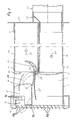
- the wall box shown in FIG. 1 has a box housing 1 molded in one piece from plastic, which is divided by a horizontal partition 3 into an upper supply air duct 5 and a lower exhaust air duct 7.
- the supply air duct 5 has a smaller height and thus a smaller cross section than the exhaust air duct 7, the inlet opening 9 of the supply air duct 5 being additionally reduced.
- the inlet opening 9 is also additionally separated from the outlet opening 11b by a front cover 9a designed as a web, in order to deliberately keep the air streams apart outside the wall box.
- the box housing 1 is installed in a wall opening in such a way that the left side in FIG. 1 lies on the outside of the building and represents the fresh air side.
- a ventilation grille 11 is placed on this end of the box housing 1.
- the supply air duct 5 and the exhaust air duct 7 open into plug connections 13, 15 of the same height and thus the same cross-sectional dimensions, and further duct elements 17, 19 are inserted into these plug connections 13, 15. the length of which is dimensioned to match the respective wall thickness of the building's outer wall.
- the channel elements 17, 19 and the associated plug connections 13, 15 preferably have a flat channel cross section, ie a rectangular cross section with rounded corners.
- a closing part 21 is plugged onto the channel elements 17, 19, which forms an outlet grille 23 for the fresh air channel element 17, while the opening of the exhaust air channel element 19 remains free for the insertion of an adapter piece 25, which is the transition to one of the Exhaust fan coming duct member 27 forms.
- the adapter piece 25 is designed in accordance with the respective cross-sectional shape of the channel element 27, for example flat channel element, round channel element, etc.
- a supply air flap 29 designed as a check valve is pivotally mounted about a horizontal transverse axis 31.
- the pivot axis 31 is located in the upper region of the supply air flap 29, so that the supply air flap 29 is loaded by its own weight into the (dash-dotted lines) closed position, which is defined by a stop shoulder 3 'of the partition 3. If there is sufficient overpressure on the outside of the building or underpressure in the interior of the room, the supply air flap 29 can open and release the fresh air flow in the direction of arrow 33. Air flow in the opposite direction is prevented by the non-return effect of the supply air flap 29.
- an exhaust air flap 35 designed as a non-return flap is pivotally mounted at its upper end about a horizontal pivot axis 37. It is loaded by its own weight in the closed position indicated by dash-dotted lines, in which it bears against a stop shoulder 1 'of the box housing 1 and closes the inlet opening of the exhaust air duct 7. If the ventilation fan generates sufficient pressure, the exhaust air flap 35 opens and releases the exhaust air flow in the direction of arrow 39.
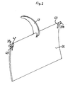
- a crescent-shaped extension projecting upwards is formed, which has only a small width in the direction of the pivot axis 37 (see FIG. 2) and through a correspondingly narrow slot 43 in the partition 3 upwards into the supply air duct 5 or the subsequent supply air duct element 17 protrudes.
- This extension engages as a blocking element 41 in the pivoting range of the supply air flap 29.
- the blocking element 41 bears against the supply air flap 29 and blocks it in its closed position, as shown in dash-dot lines. Natural air pressure differences are then not sufficient to open the supply air flap 29 against the pressure of the blocking element 41.
- the blocking element 41 move from the supply air flap 29 away and releases them.
- the supply air flap 29 is not necessarily opened, but only opens when there is a sufficient pressure difference in the supply air duct 5 in the direction of the arrow 33.
- the blocking element 41 can grip the supply air flap 29, the pivoting path of the supply air flap 29 in the opening direction is limited by a stop 45.
- the exhaust flap 35 is preferably a one-piece plastic part, in the middle of which the upwardly extending crescent-shaped extension is formed as a blocking element 41, while at the upper ends of the exhaust air flap 35 there is a pin 37a, 37b each to form the pivot axis 37 is molded. Slits 47 are provided to give the pin 37a, 37b sufficient flexibility in the axial direction so that they can be snapped into corresponding bearing openings in the side wall of the box housing 1.
- the supply air flap 9 is also formed as a one-piece plastic part with laterally molded bearing pins.
- the crescent-shaped extension of the exhaust air flap 35 acts not only as a blocking element 41, but also as a counterweight or counterweight for the exhaust air flap 35
- the center of gravity of the locking element 41 is arranged such that it lies in the (dash-dotted) closed position of the exhaust flap 35 in FIG. 1 to the left of the pivot axis 37 and thus presses the exhaust flap 35 into the closed position.
- the center of gravity of the blocking element 41 moves through the vertical plane running through the pivot axis 37, and after overcoming this dead center, the weight of the blocking element 41 has a supporting effect on the opening movement of the exhaust air flap 35.
- the shape and counterweight ensure easy opening even with a low exhaust air flow and for fully opening the exhaust air flap 35 with a strong exhaust air flow. This has a stabilizing effect on the movement of the exhaust air flap 35.
- the weight of the blocking element 41 is smaller than that of the exhaust air flap 35 itself, so that it returns to the closed position by its own weight when the pressure of the exhaust air flow 39 goes towards 0.
Landscapes
- Engineering & Computer Science (AREA)
- Chemical & Material Sciences (AREA)
- Combustion & Propulsion (AREA)
- Mechanical Engineering (AREA)
- General Engineering & Computer Science (AREA)
- Air-Flow Control Members (AREA)
- Building Environments (AREA)
- Refrigerator Housings (AREA)
- Connection Or Junction Boxes (AREA)
Applications Claiming Priority (2)
| Application Number | Priority Date | Filing Date | Title |
|---|---|---|---|
| DE3939658A DE3939658A1 (de) | 1989-11-30 | 1989-11-30 | Lueftungs-mauerkasten |
| DE3939658 | 1989-11-30 |
Publications (3)
| Publication Number | Publication Date |
|---|---|
| EP0430293A2 true EP0430293A2 (fr) | 1991-06-05 |
| EP0430293A3 EP0430293A3 (en) | 1992-05-13 |
| EP0430293B1 EP0430293B1 (fr) | 1995-01-25 |
Family
ID=6394534
Family Applications (1)
| Application Number | Title | Priority Date | Filing Date |
|---|---|---|---|
| EP90123000A Expired - Lifetime EP0430293B1 (fr) | 1989-11-30 | 1990-11-30 | Boîte d'aération pour maçonnerie |
Country Status (3)
| Country | Link |
|---|---|
| EP (1) | EP0430293B1 (fr) |
| AT (1) | ATE117789T1 (fr) |
| DE (2) | DE3939658A1 (fr) |
Families Citing this family (7)
| Publication number | Priority date | Publication date | Assignee | Title |
|---|---|---|---|---|
| RU2147105C1 (ru) * | 1999-08-23 | 2000-03-27 | ООО НТЦ "Норд" | Вентиляционная камера и способ ее работы |
| DE102004052074A1 (de) * | 2004-10-26 | 2006-04-27 | Valeo Klimasysteme Gmbh | Luftklappe mit Gegengewicht |
| DE202005010912U1 (de) † | 2005-07-12 | 2005-11-10 | Berbel Ablufttechnik Gmbh | Luftführungskasten |
| DE102006053208B4 (de) * | 2006-11-11 | 2009-09-03 | Naber Holding Gmbh & Co. Kg | Mauerkasten |
| DE102006056266B4 (de) * | 2006-11-27 | 2012-12-13 | Miele & Cie. Kg | Dunstabzugsvorrichtung mit im Abluftkanal schwenkbar gelagerter Rückschlagklappe |
| CN111023368B (zh) * | 2019-12-28 | 2022-02-15 | 深圳市开普俊梦室内设计有限公司 | 一种带温控装置的建筑结构 |
| CN112880177B (zh) * | 2021-03-22 | 2024-12-03 | 珠海格力电器股份有限公司 | 挡风板结构及具有其的空调器 |
Family Cites Families (4)
| Publication number | Priority date | Publication date | Assignee | Title |
|---|---|---|---|---|
| CH193560A (de) * | 1936-08-25 | 1937-10-31 | Baur Bernhard | Lüftungsvorrichtung. |
| US3158082A (en) * | 1961-05-10 | 1964-11-24 | Theodore L Dillingham | Air conditioning system and ventilator therefor |
| DE3103458C2 (de) * | 1981-02-02 | 1986-02-27 | Friedrich 8000 München Bürcher | Ab-und Zuluft-Mauerkasten |
| US4493341A (en) * | 1982-11-17 | 1985-01-15 | Wilhelm Gebhardt Gmbh | Blower unit for air-conditioning plant |
-
1989
- 1989-11-30 DE DE3939658A patent/DE3939658A1/de active Granted
-
1990
- 1990-11-30 AT AT90123000T patent/ATE117789T1/de not_active IP Right Cessation
- 1990-11-30 EP EP90123000A patent/EP0430293B1/fr not_active Expired - Lifetime
- 1990-11-30 DE DE59008351T patent/DE59008351D1/de not_active Expired - Fee Related
Also Published As
| Publication number | Publication date |
|---|---|
| DE3939658C2 (fr) | 1991-11-28 |
| EP0430293A3 (en) | 1992-05-13 |
| ATE117789T1 (de) | 1995-02-15 |
| DE3939658A1 (de) | 1991-06-06 |
| DE59008351D1 (de) | 1995-03-09 |
| EP0430293B1 (fr) | 1995-01-25 |
Similar Documents
| Publication | Publication Date | Title |
|---|---|---|
| DE19822173B4 (de) | Vorrichtung zur Heizung und/oder Klimatisierung eines Fahrzeuginnenraumes | |
| DE10051643B4 (de) | Haube für einen Lüfterfilter | |
| EP0430293A2 (fr) | Boîte d'aération pour maçonnerie | |
| CH453629A (de) | Einrichtung zur Belüftung von Gebäuderäumen | |
| DE4039164C2 (de) | Drosselklappe für eine Klimaanlage | |
| DE3103458C2 (de) | Ab-und Zuluft-Mauerkasten | |
| DE60016116T2 (de) | Lüftungsgitter, insbesondere für Kraftfahrzeuge | |
| DE69402625T2 (de) | Automatischer Durchflussmengenregler für Lüftungs- und Klimaanlagen | |
| EP0441271A2 (fr) | Armoire | |
| DE8914918U1 (de) | Lüftungs-Mauerkasten | |
| EP1005621B1 (fr) | Dispositif de ventillation pour elements de fenetre | |
| EP3282205A2 (fr) | Dispositif de reprise d'air | |
| DE3832474C2 (de) | Vorrichtung zur Wahl des von einer Raumluftaufbereitungseinheit angesaugten Luftstromes | |
| DE29921176U1 (de) | Absaugvorrichtung | |
| EP0671522B1 (fr) | Lucarne | |
| DE69209844T2 (de) | Vorrichtung zum steuern der luftströmung | |
| DE2557582C3 (de) | Überdruckklappe für Ventilator | |
| DE69400879T2 (de) | Selbstregelnder Lüftungsrost | |
| DE3907476C2 (de) | Lüftungsmauerkasten | |
| DE1604198C (de) | Lamelle fur eine Ventilator jalousie | |
| DE102004046210B4 (de) | Belüftungsvorrichtung und Gebäude mit einer Belüftungsvorrichtung | |
| DE19735674C1 (de) | Belüftungseinrichtung für Fensterelemente | |
| DE20314980U1 (de) | Belüftungsvorrichtung | |
| CH650586A5 (en) | Wall box for conducting incoming air and outgoing air | |
| EP3929392A1 (fr) | Aérateur à guillotine de fenêtre |
Legal Events
| Date | Code | Title | Description |
|---|---|---|---|
| PUAI | Public reference made under article 153(3) epc to a published international application that has entered the european phase |
Free format text: ORIGINAL CODE: 0009012 |
|
| AK | Designated contracting states |
Kind code of ref document: A2 Designated state(s): AT BE CH DE GB LI LU NL SE |
|
| PUAL | Search report despatched |
Free format text: ORIGINAL CODE: 0009013 |
|
| AK | Designated contracting states |
Kind code of ref document: A3 Designated state(s): AT BE CH DE GB LI LU NL SE |
|
| 17P | Request for examination filed |
Effective date: 19920612 |
|
| 17Q | First examination report despatched |
Effective date: 19930727 |
|
| GRAA | (expected) grant |
Free format text: ORIGINAL CODE: 0009210 |
|
| AK | Designated contracting states |
Kind code of ref document: B1 Designated state(s): AT BE CH DE GB LI LU NL SE |
|
| PG25 | Lapsed in a contracting state [announced via postgrant information from national office to epo] |
Ref country code: NL Effective date: 19950125 Ref country code: GB Effective date: 19950125 Ref country code: BE Effective date: 19950125 |
|
| REF | Corresponds to: |
Ref document number: 117789 Country of ref document: AT Date of ref document: 19950215 Kind code of ref document: T |
|
| REF | Corresponds to: |
Ref document number: 59008351 Country of ref document: DE Date of ref document: 19950309 |
|
| PG25 | Lapsed in a contracting state [announced via postgrant information from national office to epo] |
Ref country code: SE Effective date: 19950425 |
|
| NLV1 | Nl: lapsed or annulled due to failure to fulfill the requirements of art. 29p and 29m of the patents act | ||
| GBV | Gb: ep patent (uk) treated as always having been void in accordance with gb section 77(7)/1977 [no translation filed] |
Effective date: 19950125 |
|
| PLBE | No opposition filed within time limit |
Free format text: ORIGINAL CODE: 0009261 |
|
| STAA | Information on the status of an ep patent application or granted ep patent |
Free format text: STATUS: NO OPPOSITION FILED WITHIN TIME LIMIT |
|
| PG25 | Lapsed in a contracting state [announced via postgrant information from national office to epo] |
Ref country code: LU Free format text: LAPSE BECAUSE OF NON-PAYMENT OF DUE FEES Effective date: 19951130 |
|
| 26N | No opposition filed | ||
| REG | Reference to a national code |
Ref country code: CH Ref legal event code: PFA Free format text: MARLEY WERKE GMBH TRANSFER- MARLEY DEUTSCHLAND GMBH |
|
| PGFP | Annual fee paid to national office [announced via postgrant information from national office to epo] |
Ref country code: AT Payment date: 20011123 Year of fee payment: 12 |
|
| PGFP | Annual fee paid to national office [announced via postgrant information from national office to epo] |
Ref country code: CH Payment date: 20011126 Year of fee payment: 12 |
|
| PGFP | Annual fee paid to national office [announced via postgrant information from national office to epo] |
Ref country code: DE Payment date: 20020122 Year of fee payment: 12 |
|
| PG25 | Lapsed in a contracting state [announced via postgrant information from national office to epo] |
Ref country code: LI Free format text: LAPSE BECAUSE OF NON-PAYMENT OF DUE FEES Effective date: 20021130 Ref country code: CH Free format text: LAPSE BECAUSE OF NON-PAYMENT OF DUE FEES Effective date: 20021130 Ref country code: AT Free format text: LAPSE BECAUSE OF NON-PAYMENT OF DUE FEES Effective date: 20021130 |
|
| PG25 | Lapsed in a contracting state [announced via postgrant information from national office to epo] |
Ref country code: DE Free format text: LAPSE BECAUSE OF NON-PAYMENT OF DUE FEES Effective date: 20030603 |
|
| REG | Reference to a national code |
Ref country code: CH Ref legal event code: PL |