EP0430323B1 - Dispositif pour la récupération d'argent - Google Patents
Dispositif pour la récupération d'argent Download PDFInfo
- Publication number
- EP0430323B1 EP0430323B1 EP90202985A EP90202985A EP0430323B1 EP 0430323 B1 EP0430323 B1 EP 0430323B1 EP 90202985 A EP90202985 A EP 90202985A EP 90202985 A EP90202985 A EP 90202985A EP 0430323 B1 EP0430323 B1 EP 0430323B1
- Authority
- EP
- European Patent Office
- Prior art keywords
- holder
- liquid
- recovery device
- resin
- silver recovery
- Prior art date
- Legal status (The legal status is an assumption and is not a legal conclusion. Google has not performed a legal analysis and makes no representation as to the accuracy of the status listed.)
- Expired - Lifetime
Links
- BQCADISMDOOEFD-UHFFFAOYSA-N Silver Chemical compound [Ag] BQCADISMDOOEFD-UHFFFAOYSA-N 0.000 title claims description 82
- 229910052709 silver Inorganic materials 0.000 title claims description 82
- 239000004332 silver Substances 0.000 title claims description 82
- 238000011084 recovery Methods 0.000 title claims description 67
- 239000007788 liquid Substances 0.000 claims description 128
- 239000011347 resin Substances 0.000 claims description 102
- 229920005989 resin Polymers 0.000 claims description 102
- 239000008237 rinsing water Substances 0.000 claims description 61
- 238000011069 regeneration method Methods 0.000 claims description 48
- 230000008929 regeneration Effects 0.000 claims description 47
- NWUYHJFMYQTDRP-UHFFFAOYSA-N 1,2-bis(ethenyl)benzene;1-ethenyl-2-ethylbenzene;styrene Chemical compound C=CC1=CC=CC=C1.CCC1=CC=CC=C1C=C.C=CC1=CC=CC=C1C=C NWUYHJFMYQTDRP-UHFFFAOYSA-N 0.000 claims description 45
- 239000003456 ion exchange resin Substances 0.000 claims description 45
- 229920003303 ion-exchange polymer Polymers 0.000 claims description 45
- 238000012545 processing Methods 0.000 claims description 20
- 108010010803 Gelatin Proteins 0.000 claims description 13
- 229920000159 gelatin Polymers 0.000 claims description 13
- 239000008273 gelatin Substances 0.000 claims description 13
- 235000019322 gelatine Nutrition 0.000 claims description 13
- 235000011852 gelatine desserts Nutrition 0.000 claims description 13
- 238000005192 partition Methods 0.000 claims description 8
- 238000004891 communication Methods 0.000 claims description 6
- 238000005086 pumping Methods 0.000 claims description 6
- 238000007667 floating Methods 0.000 claims description 3
- 238000010438 heat treatment Methods 0.000 claims description 3
- 230000010354 integration Effects 0.000 claims description 3
- 230000001172 regenerating effect Effects 0.000 claims description 3
- XLYOFNOQVPJJNP-UHFFFAOYSA-N water Substances O XLYOFNOQVPJJNP-UHFFFAOYSA-N 0.000 description 34
- 230000003115 biocidal effect Effects 0.000 description 20
- 239000003139 biocide Substances 0.000 description 20
- 238000005342 ion exchange Methods 0.000 description 11
- 238000000034 method Methods 0.000 description 9
- 238000009434 installation Methods 0.000 description 7
- 230000003716 rejuvenation Effects 0.000 description 5
- 230000008901 benefit Effects 0.000 description 4
- 150000002500 ions Chemical class 0.000 description 4
- 230000004044 response Effects 0.000 description 4
- 230000011664 signaling Effects 0.000 description 4
- 238000010276 construction Methods 0.000 description 3
- 230000000694 effects Effects 0.000 description 3
- 230000005484 gravity Effects 0.000 description 3
- 210000002445 nipple Anatomy 0.000 description 3
- 239000004033 plastic Substances 0.000 description 3
- 229920003023 plastic Polymers 0.000 description 3
- 230000008569 process Effects 0.000 description 3
- 239000012508 resin bead Substances 0.000 description 3
- 230000000630 rising effect Effects 0.000 description 3
- VEXZGXHMUGYJMC-UHFFFAOYSA-M Chloride anion Chemical compound [Cl-] VEXZGXHMUGYJMC-UHFFFAOYSA-M 0.000 description 2
- ZSILVJLXKHGNPL-UHFFFAOYSA-L S(=S)(=O)([O-])[O-].[Ag+2] Chemical class S(=S)(=O)([O-])[O-].[Ag+2] ZSILVJLXKHGNPL-UHFFFAOYSA-L 0.000 description 2
- 230000005791 algae growth Effects 0.000 description 2
- 230000002950 deficient Effects 0.000 description 2
- 238000007599 discharging Methods 0.000 description 2
- 239000012530 fluid Substances 0.000 description 2
- 239000002245 particle Substances 0.000 description 2
- 230000002441 reversible effect Effects 0.000 description 2
- 238000003892 spreading Methods 0.000 description 2
- 230000007480 spreading Effects 0.000 description 2
- 239000008399 tap water Substances 0.000 description 2
- 235000020679 tap water Nutrition 0.000 description 2
- 239000004677 Nylon Substances 0.000 description 1
- 239000004698 Polyethylene Substances 0.000 description 1
- 230000009471 action Effects 0.000 description 1
- 239000003957 anion exchange resin Substances 0.000 description 1
- 230000002547 anomalous effect Effects 0.000 description 1
- 238000013459 approach Methods 0.000 description 1
- 230000015572 biosynthetic process Effects 0.000 description 1
- 230000000903 blocking effect Effects 0.000 description 1
- 238000004140 cleaning Methods 0.000 description 1
- 230000006835 compression Effects 0.000 description 1
- 238000007906 compression Methods 0.000 description 1
- 230000007423 decrease Effects 0.000 description 1
- 230000007547 defect Effects 0.000 description 1
- 230000001419 dependent effect Effects 0.000 description 1
- 238000001514 detection method Methods 0.000 description 1
- 238000010586 diagram Methods 0.000 description 1
- 238000006073 displacement reaction Methods 0.000 description 1
- 238000009826 distribution Methods 0.000 description 1
- 238000005516 engineering process Methods 0.000 description 1
- 239000004744 fabric Substances 0.000 description 1
- 239000013505 freshwater Substances 0.000 description 1
- 229920001903 high density polyethylene Polymers 0.000 description 1
- 239000004700 high-density polyethylene Substances 0.000 description 1
- 238000003384 imaging method Methods 0.000 description 1
- 230000000977 initiatory effect Effects 0.000 description 1
- 238000004519 manufacturing process Methods 0.000 description 1
- 239000000463 material Substances 0.000 description 1
- 238000005259 measurement Methods 0.000 description 1
- 229920001778 nylon Polymers 0.000 description 1
- 230000002093 peripheral effect Effects 0.000 description 1
- -1 polyethylene Polymers 0.000 description 1
- 229920000573 polyethylene Polymers 0.000 description 1
- 238000001556 precipitation Methods 0.000 description 1
- 230000002028 premature Effects 0.000 description 1
- 238000002360 preparation method Methods 0.000 description 1
- 230000000284 resting effect Effects 0.000 description 1
- 150000003839 salts Chemical class 0.000 description 1
- 150000003378 silver Chemical class 0.000 description 1
- 239000007787 solid Substances 0.000 description 1
- 230000002269 spontaneous effect Effects 0.000 description 1
- 230000002459 sustained effect Effects 0.000 description 1
- 238000012546 transfer Methods 0.000 description 1
- 238000005406 washing Methods 0.000 description 1
- 239000002699 waste material Substances 0.000 description 1
Images



Classifications
-
- C—CHEMISTRY; METALLURGY
- C01—INORGANIC CHEMISTRY
- C01G—COMPOUNDS CONTAINING METALS NOT COVERED BY SUBCLASSES C01D OR C01F
- C01G5/00—Compounds of silver
- C01G5/003—Preparation involving a liquid-liquid extraction, an adsorption or an ion-exchange
-
- B—PERFORMING OPERATIONS; TRANSPORTING
- B01—PHYSICAL OR CHEMICAL PROCESSES OR APPARATUS IN GENERAL
- B01J—CHEMICAL OR PHYSICAL PROCESSES, e.g. CATALYSIS OR COLLOID CHEMISTRY; THEIR RELEVANT APPARATUS
- B01J47/00—Ion-exchange processes in general; Apparatus therefor
- B01J47/10—Ion-exchange processes in general; Apparatus therefor with moving ion-exchange material; with ion-exchange material in suspension or in fluidised-bed form
-
- C—CHEMISTRY; METALLURGY
- C22—METALLURGY; FERROUS OR NON-FERROUS ALLOYS; TREATMENT OF ALLOYS OR NON-FERROUS METALS
- C22B—PRODUCTION AND REFINING OF METALS; PRETREATMENT OF RAW MATERIALS
- C22B3/00—Extraction of metal compounds from ores or concentrates by wet processes
- C22B3/02—Apparatus therefor
-
- G—PHYSICS
- G03—PHOTOGRAPHY; CINEMATOGRAPHY; ANALOGOUS TECHNIQUES USING WAVES OTHER THAN OPTICAL WAVES; ELECTROGRAPHY; HOLOGRAPHY
- G03C—PHOTOSENSITIVE MATERIALS FOR PHOTOGRAPHIC PURPOSES; PHOTOGRAPHIC PROCESSES, e.g. CINE, X-RAY, COLOUR, STEREO-PHOTOGRAPHIC PROCESSES; AUXILIARY PROCESSES IN PHOTOGRAPHY
- G03C5/00—Photographic processes or agents therefor; Regeneration of such processing agents
- G03C5/26—Processes using silver-salt-containing photosensitive materials or agents therefor
- G03C5/395—Regeneration of photographic processing agents other than developers; Replenishers therefor
- G03C5/3956—Microseparation techniques using membranes, e.g. reverse osmosis, ion exchange, resins, active charcoal
-
- Y—GENERAL TAGGING OF NEW TECHNOLOGICAL DEVELOPMENTS; GENERAL TAGGING OF CROSS-SECTIONAL TECHNOLOGIES SPANNING OVER SEVERAL SECTIONS OF THE IPC; TECHNICAL SUBJECTS COVERED BY FORMER USPC CROSS-REFERENCE ART COLLECTIONS [XRACs] AND DIGESTS
- Y02—TECHNOLOGIES OR APPLICATIONS FOR MITIGATION OR ADAPTATION AGAINST CLIMATE CHANGE
- Y02P—CLIMATE CHANGE MITIGATION TECHNOLOGIES IN THE PRODUCTION OR PROCESSING OF GOODS
- Y02P10/00—Technologies related to metal processing
- Y02P10/20—Recycling
Definitions
- the present invention relates to a silver recovery device for recovering silver from photographic rinsing water by ion exchange.
- Ion exchange can be defined as a reversible exchange of ions between a solid (resin) and a liquid (water containing ionized salts).
- Silver in the rinsing water is in the ionized form of silver complexes, more particularly silver thiosulfate compounds, e.g. [Ag(S 2O3)2] ⁇ 3 and [Ag(S2O3)3] ⁇ 5.
- a strong base anion exchange resin is used to recover the silver.
- chloride is the mobile ion and it exchanges with the silver thiosulfate to release a chloride ion while capturing the silver complex, e.g. according to the following scheme : [R]+Cl + 1/3 [Ag(S2O3)2] ⁇ 3 ⁇ [R]+[Ag(S2O3)2] ⁇ 3 1/3 + Cl ⁇ .
- a serious problem encountered with ion exchange of photographic rinsing water is that gelatin clogs the resin and restricts the liquid flow.
- valves will normally be solenoid-operated and practice shows that a trouble-free operation may raise difficulties in the long run.
- a silver recovery device for recovering silver from rinsing water from photographic processing apparatus by means of a bed of ion exchange resin which is fluidized by the rinsing water, comprises a holder for ion exchange resin, said holder having a liquid inlet opening at the bottom, the device having a first and a second outlet opening for the liquid of the resin holder, the second outlet opening being located higher than the first one, circulation pump means for pumping liquid that flows out through said first outlet opening to the inlet opening of the resin holder, the inlet of the device being at the suction side of the circulation pump means, and the outlet of the device being at the second outlet opening.
- the silver recovery device comprises control means for controlling the operation of the circulation pump means such that during the operative period of the photographic processing apparatus said pump means is continuously operative, and that during at least part of the inoperative period of the apparatus the operation of the pump means is intermittent. It has been shown that this way of operation is very effective to liberate gelatin that might have been deposited on the resin and that tends to clog the mass of resin, since under the influence of gravity the resin bed slowly sinks to the bottom of the holder and expands its volume.
- the pump means may be controlled to obtain also during the operative period of the photographic processor short rest periods during which the resin bed is no longer fluidized and sinks slowly to the bottom of the cartridge.
- a further embodiment of the invention is as follows.
- the ion exchange resin holder is in the form of a tank, and the resin is contained in a cartridge which removably fits in the tank.
- This feature has the advantage of easy replacement of a used resin, by lifting a cartridge with used resin from the tank and substituting a cartridge with fresh resin.
- Such fresh resin may be new resin, but it may also be, and preferably is, used resin that has been regenerated.
- Regeneration may be carried out by placing a cartridge with used resin in another holder wherein a liquid flow is sustained that can regenerate used resin.
- This liquid flow may suitably be the fixing circuit of the photographic processing apparatus since a fixing solution may have a regenerating effect on a used ion exchange resin, depending on the type of resin.
- a still further embodiment of the invention is one in which the ion exchange resin is not contained in a cartridge that is transferable in view of its regeneration, but instead the ion exchange resin holder has the form of a container or pack which is connected into the liquid circuit of the recovery device.
- the container may be connected in the circuit through three-way valves, so that in the periods of use and rest of the ion exchange resin the container is connected in the rinsing water circuit of the photographic processor, but that for the regeneration of the resin the container becomes switched in the fixer circuit of the processor. In this way the operator of the processor must not perform any handling with the container with the ion exchange resin. It has been shown that the sequences of use and regeneration of the resin can go on for several years. When the moment has come to replace the resin, a service man simply has to disconnect the container from the liquid circuit of the processor, and to replace it by a new one.
- the latter shall preferably be provided with an electrolytic silver recovery device in order to keep the silver contents of the fixer liquid sufficiently low.
- the first and second outlet opening of the device are formed in a separate control holder which is in liquid communication with the holder with the ion exchange resin, said control holder having a bottom opening which communicates with the inlet of the circulation pump means.
- This construction has the advantage that the holder for the ion exchange resin need only be a simple envelope, in the form of a container or pack, with only an inlet and an outlet connection, arranged for easy manifolding in the circuit.
- the functions of the two distinct outlet openings are in this case performed by the control holder which constitutes a permanent part of the device.
- the inlet of the device may in the case of a separate control holder be formed by a connection in the conduit from the control holder to the suction side of the pump means, but the inlet may also be formed by a separate inlet opening in the control holder.
- the first and second outlet opening are common to one conduit that supplies liquid that passed through the ion-exchange resin, the first outlet opening discharging into the control holder and the second outlet opening discharging in a next holder and having a flow resistance such that liquid only starts to flow out after the back-pressure on the first opening has reached a certain value.
- valve means e.g. in the form of a ball floating on the liquid in the control holder, said floating ball co-operating directly with the said first outlet opening in said holder.
- the closing of the first opening may also occur by the liquid itself, such as in the case in which this opening is located well below the normal level of the liquid in the holder so that the liquid in the holder causes a back pressure which is sufficient to cause the liquid to start to flow out at an increased rate through the higher located second opening.
- the exact level control of the control holder may be obtained by dividing the control holder in two compartments which communicate with each other via an opening at the bottom, the second compartment having an overflow edge which forms the second outlet of the holder, the first outlet opening being located in the first compartment of the holder.
- a liquid sensor may be provided in the control holder at a height such that it is above the liquid level in the holder that is established when no fresh rinsing water is being received from the processor, but such that it senses liquid when the device is receiving fresh rinsing water.
- the silver recovery device comprises at least two holders with ion exchange resin, which are connected in series so that they operate in cascade.
- each individual device may operate at its optimum efficiency based on the continuous circulation of the water through its resin bed, and that occasional clogging of the resin mass of one holder does not render the installation inoperative since the rinsing water will simply fill the clogged holder up to the second outlet opening and then flow to the next holder.
- This spontaneous by-passing of a defect holder is an important feature of the invention.
- the arrangement with the circulation pump means that pumps liquid flowing out through the first outlet opening back to the inlet opening of the resin holder has for consequence that this liquid is added to the liquid being received from the processor and going directly to the inlet of the resin holder.
- a photographic film processor 10 which comprises a developing station 11, a fixing station 12 and a rinsing or washing station 13, is connected to an ecological processing unit 15 which comprises a module 16 with a holder 17 for used developer and a holder 18 for used fixer, a module 19 for the recovery of silver from the fixer liquid, and a module 20 for the recovery of silver from the rinsing water.
- the processor 10 and the unit 15 have been illustrated as separate units in Fig. 1, and in practice they may be located close to each other or even be arranged in separate rooms. However, the unit 15 may also be integrated with the processor 10.
- the holders 17 and 18 may be in the form of small tanks, jerrycans, canisters, and the like.
- the developing station 11 comprises a regeneration system 21 for adding regeneration liquid to the station as developer is being consumed by the developed film and dragged into the fixing station.
- the fixing station 12 comprises a regeneration system 23 for the fixer liquid.
- the processing stations may be deep tanks with film transport racks, or shallow tanks for a nearly horizontal film transport. The cross-over between adjacent tanks may be provided with squeegee roller pairs or the like for limiting the transfer of processing liquid into the next tank, all as known in the art.
- the developing station 11 has an overflow 24 which controls the liquid level in the station, and which leads to the holder 17.
- a pump 39 maintains a circulation of developing liquid in the station.
- a heater element 40 controls the temperature of the developer.
- the fixing station 12 has an overflow 25 which leads to the electrolytic silver recovery device 26 of the module 19.
- a first pump 27 ensures the circulation of fixing liquid through the recovery device 26, whereas a second pump 28 pumps the liquid to a three-way valve 29 that normally conducts the liquid back to the fixing station, via the ion-exchange recovery module 20, but that may also conduct the liquid to the holder 18 for used fixer.
- the valve 29 is controlled by a solenoid 30 in response to the signal from a level sensor 31 in the device 26 so that as the liquid level in the device 26 exceeds a set value, as after the addition of regenerating liquid to the fixing station, the valve is switched to conduct the excess liquid to the holder 18.
- a restrictor 32 permits to adjust the rate of flow of fixer liquid to the fixing station.
- a pump 42 maintains a circulation of fixer liquid through the fixing station.
- a heater element 43 controls the temperature of the fixer.
- the rinsing station 13 has an overflow 34 which leads towards the module 20.
- Rinsing water is taken from a tap water connection 35 under the control of a valve 36 which may be controlled by a sensor 37 in response to the introduction of a film 38 into the processor.
- the module 20 is described hereinafter in detail with reference to Fig. 2 in which the numbering of the liquid in- and outlets 45 through 49 corresponds with that of Fig. 1.
- the module 20 comprises a number of liquid tanks, pumps and valves which are mounted within a cabinet which as such need not necessarily be liquid-tight, but which may have a dripping pan 50 for collecting liquid that may leak from a tank upon servicing the tank, and for draining such liquid to the sewer via the conduit 87.
- the module 20 comprises a group of three silver recovery tanks 51, 52 and 53, a group of resin regeneration tanks 54, 56 and 57, and a tank 58 with a biocide.
- Tanks 51 through 57 are arranged for holding resin cartridges 61 through 66, and may suitably be formed by six compartments of one holder 60, as illustrated by the partly broken-away perspective drawing of Fig.3. The in- and outlets have not been illustrated in this figure.
- Each cartridge is basically a rectangular holder with a perforate bottom wall 69 and perforate top wall 70, as illustrated for the cartridge 61.
- the perforate walls may suitably be formed by a net of a plastic fabric, such as nylon, which is heat-sealed to the peripheral rim of the top and bottom opening of the holder.
- the cartridge is suitably made from a plastic that readily lends itself to ecological disposal, e.g. polyethylene.
- Each cartridge contains an amount of an ion-exchange resin which is such that sufficient space is left for the liberation and spreading of the resin as the operation of the cartridge is stopped, as will be described in detail hereinafter. Suitable filling ratio of the inner volume of the cartridge are between 60 and 95 %.
- the cartridges can be freely lowered in the tank compartments, and are arranged for being liquid-tightly sealed at their bottom periphery by a rim such as the rim 68 illustrated for the cartridge 64.
- the cartridges are urged downwardly on the rims by rib sections 11 that are provided at the underside of the cover 59 which liquid-tightly fits to the holder 60.
- liquid circuits of the tanks 51, 52 and 53 constitute in fact three identic arrangements, and therefore only the circuit of tank 51 will be described hereinafter in detail with reference to Fig. 2.
- the tank 51 has a first overflow, formed by an opening 74 in its wall, which is connected via a conduit 75 with the suction end of a centrifugal-type circulation pump 76.
- the pressure end of the pump is connected via 88 with the inlet opening 78 in the bottom of the tank.
- the tank has a second overflow formed by an opening 79 which is located slightly higher than the first one, and which forms the outlet of the tank for the cleaned rinsing water.
- the pump 76 maintains a continuous circulation of liquid through the tank, the liquid flowing upwardly through the cartridge 61, and back via the overflow opening 74 and the conduit 75.
- the conduit 75 which leads to the suction end of the pumps 76 forms the inlet of the circuit, and this conduit is connected via the upper branch of the three-way valve 80 with the inlet 45 which receives water from the overflow 34 of the rinsing station 13 of the processor.
- the level of the liquid in the recovery tank 51 increases till the level of the second overflow opening 79 is reached.
- the rinsing water is discharged into the inlet end of the second tank circuit, viz. into the conduit 82, and the water is circulated so long in the second tank circuit till the level of the second overflow opening of this second circuit is reached, what leads to a discharge into the third recovery tank 53.
- the process is repeated in this third tank until finally the water is discharged into the conduit 83 which leads to the discharge point 48 which is in connection with the conduit 55 to the sewer.
- the purpose of the three-way valve 80 is to bring about the connection between inlet 45 of the recovery device and the sewer via the conduits 85 and 55 during the cleaning of the rinsing tank of the processor, so as to avoid that servicing products would enter the recovery device and destroy the function of the ion exchanger resin.
- the conduit 87 connects the pan 50 with the outlet 49, and so also to the sewer.
- Each recovery tank may be provided with a pressure sensor such as 89 for measuring the back-pressure produced by the ion-exchange cartridge, and for producing a warning signal as the pressure exceeds a pre-set value, pointing to an unsatisfactory operation of a cartridge.
- the recovery tanks have drain valves 90, 91 and 92 for draining the tanks in view of their servicing.
- the tanks 54, 56 and 57 of the second group form the resin regeneration tanks as mentioned already.
- the tanks are arranged for receiving the cartridges from the recovery tanks as their efficiency has dropped below a certain value.
- the liquid flow between the tanks is as indicated by the arrows.
- the regeneration of the ion-exchange resin of the cartridges occurs in the present example by means of the fixing solution of the processor. It will be understood that the latter technique requires the use of a resin type that lends itself to this way of regeneration.
- the three regeneration tanks are connected in series with the circuit of the fixer of the processor 10 via the connections 46 and 47.
- a three-way valve 99 is controlled by a controller 97 in such a way that normally the upper branch of the valve is in the circuit, what means that the points 46 and 47 are in fact short-circuited whereby the fixing liquid flows directly from the valve 29 to the fixing station 12.
- the controller 97 connects the lower branch of the valve 99 in the circuit so that now the fixer flows from connection 46 through the regeneration tanks, and then to connection 47. Further, the valve 99 may also be controlled in response to the the silver rate of the fixer circuit, thereby to start the resin regeneration only when the silver rate of the fixer is below a certain value, e.g. below 0.2 g of silver per liter of fixer. Finally, there are valves 93 and 94 for draining the regeneration tanks.
- the tank 58 is connected to three identic volumetric displacement pumps 95 for delivering at the appropriate moment a controlled volume of a biocide to the recovery tanks 51, 52 and 53.
- the operation of the recovery device 20 is controlled by the controller 97 in the following way.
- the controller 97 controls the circulation pumps 76, 67 and 77 to rotate uninterruptedly thereby to remove silver from the rinsing water in the respective circuits.
- the controller 97 also controls the three-way valve 99 to connect the regeneration tanks 54, 56 and 57 to the circuit according to a pre-set time program.
- the controller 97 controls the pumps 76, 67 and 77 to rotate intermittently.
- intermittent means in the present context that the pumps are made to run and to stop for periods that may have for instance a ratio between 1:1 and 1:10, the minimum absolute value of a running period being some minutes.
- controller 97 controls the operation of the pumps 95 so that a controlled quantity of biocide is fed to the resin cartridges 61, 62 and 63 of the recovery tanks 51, 52 and 53, at a moment the processor is inoperative. In this way it is made sure that the biocide is not prematurely flushed away by new rinsing water received from the rinsing tank 13.
- a cartridge being filled with resin for only about 90 % of its volume it will be understood that the mass of resin is fluidized as the circulation pump of the recovery tank pumps rinsing water upwardly through the tank. The resin is urged as a rather compact mass against the perforate top wall of the cartridge. The rise of the resin by the operation of the pump occurs within a few seconds.
- the described operation is very effective to set free gelatin of the processed films that has been deposited on the resin and that increases the resistance to liquid flow.
- Restarting the pumps drives the resin mass within a few seconds upwardly in the cartridge, thereby to operate as a fluidized bed.
- the removed gelatin is circulated with the water and will slowly start to settle again on the resin. This settlement is less than that which occurred during the operation of the processor, since said operation continued for several hours, whereas the operation of the pumps during the inactive period of the processor covers much smaller periods, which may range between some minutes and some tens of minutes.
- fresh rinsing water is added to the rinsing tank in response to actuation of the switch 37.
- the corresponding volume of used rinsing water which flows via the overflow 34 to the recovery device, causes a corresponding volume of gelatin-loaded water circulating in the device to be drained off to the sewer.
- the efficiency of the tanks in removing silver decreases in direct proportion to the percentage of resin capacity utilized. For this reason the device is normally operated until typically 100 % of the resin efficiency of the first tank, 95 % of the second and 50 % of the third tank are utilized. This operation period may occupy several months. Then the device is arrested, and the cartridges from recovery tanks 51, 52 and 53 are transferred to the regeneration tanks 54, 56 and 57 and the regenerated cartridges from the latter group of tanks are transferred to the first group. This way of interchanging can be repeated up to 50 times, depending on the characteristics of the resin.
- the final silver recovery occurs in the device 26 which electrolytically removes the silver from the fixing solution, and thus also from the resin which was regenerated by such fixing solution.
- FIG. 4 Another embodiment of an ion-exchange cartridge is illustrated in Fig. 4.
- the cartridge is a generally square body 100 with threaded neck portions 101, 102 resp. at the top and the bottom.
- the cartridge is filled for a given volume percentage with resin particles and then also the top opening is closed by a net, see 103.
- the cartridge is delivered to the customer with two screw caps for closing the cartridge when it is removed from the device at the time it can no longer be regenerated.
- the cartridge forms then a liquid-tight receptacle which can readily be handled for its transport to an ecological disposal station.
- Suchlike members are used in the treatment of effluent water.
- such members may have a length and a width of approximately 3 cm, and comprise ribs, fins or the like interconnected to an open structure, made of an inert material such as high density polyethylene.
- These cages form obstacles in the way of the resin beads moving upward and downward in the cartridge in dependence on the starting and arresting of the pumps, and thereby they have an extra dislocating and spreading effect on the resin beads.
- Fig. 5 illustrates an other circuit for the regeneration of the ion-exchange resin.
- FIG. 1 The figure is based on the drawing of Fig. 1, but shows only those elements that are essential for illustrating the different operation.
- the fixer for the regeneration of the ion-exchange resin is no longer taken from the silver recovery module 19, but instead now the fixer which is added by the rejuvenation device 23 to the fixing tank 12 is now passed through the cartridges 64, 65 and 66 to be regenerated, via the connections 46 and 47, see also Fig.2.
- the valve 99 may remain always open so that fresh rejuvenation fixer is always passed through the regeneration circuit.
- the silver recovery device may be connected to a processor in such a way that cleaned rising water is returned to the rinsing station of the processor.
- a combination of fresh tap water with cleaned rising water may be considered.
- the regeneration of the used resin must not necessarily occur on-line by means of the fixer liquid of the processor, but may also be done off-line by means of an extra, separate fixer supply, or by the use of appropriate products, as prescribed by the manufacturer of a given type of resin.
- the number of resin cartridges may be higher or lower, and two or more cartridges or groups of cartridges may be used in parallel.
- the intermittent operation of the circulation pumps of the silver recovery tanks is not limited to the inoperative period of the processor.
- it may be considered to introduce rest periods for the pumps also during the operative period of the processor, in order to provide a further opportunity for the ion exchange resin to get rid of deposited gelatin.
- Such rest periods will preferably occur under the control of a sensor that senses the absence of a photographic film in the processor, such as the sensor 37 described hereinbefore since otherwise water could be received frop the processor which would not pass through the recovery device but which would flow directly to the sewer.
- FIG. 6 Another embodiment of an ecological processing unit according to the invention for use with the photographic film processor according to Fig. 1 is illustrated in Fig. 6 in which the in- and outlets that correspond with those of Figs. 1 and 2 received the same numerals.
- the silver recovery module 120 comprises three resin holders 110, 111 and 112 in the form of plastic packs that have an inlet nipple 113, 114 and 115 at the bottom and an outlet nipple 116, 117 and 118 at the top permitting easy manifolding of the packs into and removal from the circuit of the module, e.g. by means of hoses that are slid over the corresponding inlet and outlet nipples of the packs.
- the packs contain a mass of ion exchange resin 119 that is kept within a perforate bottom and top wall, which may suitably be formed by a net.
- the packs are in communication with three corresponding control holders 124, 125 and 126 through conduits 121, 122 and 123.
- These holders may be formed in one open tank which has partition walls to determine the mentioned holders, as well as an outflow compartment 127.
- Each control holder has two outlet openings at different levels, the function of which corresponds to that of the two outlet openings 74 and 79 of the holders 51, 52 and 53 illustrated in Fig. 2.
- the outlet openings have been numbered for the control holder 124 only, viz. 128 and 129, and they are identic for the holders 125 and 126.
- the opening 128 is in fact the lower end of an L-like pipe 130 that fits to the conduit 121, the upper end of said pipe being slightly upwardly angled and constituting the opening 129.
- Each of the three control holders has further the following provisions.
- a series of balls 130 that are urged upwardly in a guide column by the liquid and that close the opening 128 as the liquid reaches the level 148 of said opening.
- a level sensor 131 that senses a liquid level that is about 10 mm below the level 148.
- a heater 132 for heating the liquid in the holder under the control of a temperature sensor 133.
- the module 120 comprises further three circulation pumps 134, 135 and 136 for pumping liquid from bottom openings 137, 138 and 139 of the control holders to a corresponding resin pack, and also three volumetric pumps 140, 141 and 142 for withdrawing liquid from the resin packs.
- a three-way valve 147 for connecting the outlets of the pumps 140 to 142 to the fixer outlet 47, or to an additional outlet 48' the purpose of which will be explained hereinafter.
- the device comprises also a tank 58 for a biocide, and volumetric pumps 95 for pumping this biocide to the control holders.
- the operation of the device is as follows.
- the photographic processor 10 being operative, and the module 120 being connected to said processor through the corresponding connections 45 to 49, used rinsing water that is discharged through the overflow 34 of the tank 13 enters the module at 45 and flows via the valve 143 to the inlet 145 of control holder 124.
- the circulation pump 134 draws water from the holder and pumps it through the first resin pack 110.
- the water returns to the holder 124 via conduit 121, pipe 130 and opening 128. This goes on, and silver becomes gradually removed from the water by the ion exchange resin of the first pack, until the supply of water is such that a level is reached at which the balls 130 close the opening 128.
- the liquid starts to flow through the opening 129 of pipe 130, and starts to fill the second silver exchange circuit comprising control holder 125, pump 135 and resin pack 111.
- the process in the first circuit continues.
- Still further supply of used rinsing water causes also the third resin circuit with control holder 126, pump 136 and pack 112 to become involved in the liquid circulation.
- water flows through outlet 149 in the outflow compartment 127, and so to the sewer via outlet 48.
- the module 120 When the operative period of the photographic processor 10 comes to an end, e.g. in the evening, the module 120 receives no further water from the overflow 34, and the operation of the pumps 134, 135 and 136 continues in order to remove the silver from the water contained in the circuit of the module.
- the pumps 134, 135 and 136 are controlled to operate intermittently. Arrestment of these pumps causes the fluidized beds of the three resin packs slowly to desintegrate, under the influence of gravity as described hereinbefore with reference to the cartridges 61, 62 and 63 shown in Fig. 2. In the present embodiment, good results have been obtained with an intermittent operation during 4 hours, namely alternatingly 10 min operation and 10 min rest.
- the module 120 comprises electronic control means 150 for performing the following controls during the inactive period of the photographic processor.
- the volumetric pumps 140, 141 and 142 are controlled to operate until the liquid level in the control holders has lowered from the level of the openings 128 to the level detected by the sensor 131, which is approximately 1 cm lower as said already. Water withdrawn by the pumps 140, 141 and 142 is evacuated via the valve 147 to the outlet 48' and so to the sewer.
- the pumps 95 are operated to add biocide to the control holders in such an amount that the level 128 is not reached.
- heaters 132 of the control holders may be connected in the circuit so that under the control of the sensors 134 the temperature of the liquid is raised in order to facilitate the removal of gelatin from the resin packs. In the present example satisfactory results have been obtained with a temperature of 45°C.
- the pumps 134, 135 and 136 are restarted, according to an intermittent cycle as described, for a preset number of hours, e.g. 4 hours.
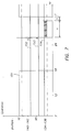
- the diagrammatic illustration of Fig. 7 gives an indication of the operation of the silver recovery device for a given 24 hrs cycle during which the photographic processor is operative from 07 to 18 hrs.
- the curve 151 illustrates the operation of the photographic processor
- the curve 152 the operation of the volumetric emptying pumps 140 to 142
- the curve 153 the operation of the biocide pumps 95
- the curve 154 shows the operation of the circulation pumps 134 to 136.
- the time period a is the 4 hours intermittent operation of the circulation pumps, whereas the period b stands for an uninterrupted a to two hours continuous operation in preparation of the restarting of the processor.
- the following measures can be taken in order to further control the resin packs during the inoperative period of the photographic processor.
- the heating circuits 132 are disconnected from the circuit to save energy.
- the processor does not start to operate within 24 hours after the intermittent operation of the pumps 134, 135 and 136, the whole cycle of slightly lowering the liquid levels, adding biocide, and increasing the temperature of the liquid may be repeated in order to keep algae growth under control.
- Valve 143 is switched to conduct water that should occasionally arrive from the processor input at 45, directly to the sewer via outlet 49.
- Pumps 140, 141 and 142 are operated for a time sufficient to evacuate all the water of the circuit to the sewer via outlet 48'.
- Valve 146 is then switched to conduct fixer that is available at the inlet connection 46 to the inlet 145.
- Fixing liquid fills in succession the first, second and third control holder, the pumps 134, 135 and 136 being operative, until the level of sensor 131 is reached which causes the valve 146 to resume the rest position whereby no further fixer is added to the circuit but connections 46 and 47 are directly interconnected to each other. In this way it is prevented that fixer would finally flow into compartment 127 and so to the sewer.
- the regeneration of the resin can go on for a pre-set number of hours which have been preassessed to produce under all circumstances a complete regeneration of the resin.
- This method has the disadvantage that in case of limited use of the photographic processor over a certain period, the regeneration time of the resin is unnecessarily long or, conversely, the moment of regeneration is unduly premature. Therefore, according to a preferred embodiment of the invention, there is performed an integration in time of the electric current in the silver recovery device 26 of the module 19 which is caused by silver which has been removed from the ion exchange resin by the fixer, and which in its turn is being removed from the fixer by the silver recuperator 26. Such integration gives an exact indication of the amount of silver which has been added to the installation, i.e. of the amount of film which has been processed.
- This information may be used to set the moment of regeneration, rather than determining this moment on the basis of a preset lapse of time.
- the size of the resin packs was such that a "normal" period of use of the processor, e.g. two months, could be expected for a regeneration period of 8 hours (which thus could occur at night).
- a "normal" period of use of the processor e.g. two months
- periods of lesser activity may well give rise to periods considerably longer than 2 months before regeneration must start, and in such case an inbuilt microprocessor may signal to the operator that the deadline for the next regeneration will probably be so much time later.
- the pumps 134, 135 and 136 are stopped, the pumps 140, 141 and 142 are made to operate for a certain period and the valves 147 and 146 are switched so that fixer withdrawn from the system is returned via outlet 47 to the fixer circuit of the processor. Then the pumps 140, 141 and 142 are stopped and the valve 147 is put in its rest position, i.e. leading towards the outlet 48'.
- the described device may comprise in practice still other sensors that are desirable for signalling anomalous operation conditions, e.g. level sensors in the control holders for signalling a level in excess of the partition walls, an "empty” sensor in the tank for the biocide, etc.
- level sensors in the control holders for signalling a level in excess of the partition walls e.g. level sensors in the control holders for signalling a level in excess of the partition walls, an "empty” sensor in the tank for the biocide, etc.
- the intermittent operation of the pumps 134, 135 and 136 may be switched into a continuous one if the photographic processing apparatus is used during the intermittent operation of these pumps.
- the level of the liquid in the control holder 126 increases until the level of the detector 131 is reached.
- This detector switches the intermittent operation of the pumps into a continuous one, so that the rinsing water does not flow directly to the sewer, but instead is pumped through the ion exchange resin packs to remove the silver therefrom before the water flows into the compartment 127.
- the outlet connection 48' need not necessarily lead to the sewer but may be connected to a recirculation system for the rinsing water.
- the pumps 134, 135 and 136 need not necessarily operate in parallel during their intermittent functioning.
- two pumps, e.g. 134 and 135 may be periodically arrested in view of the setting free of the ion exchange resin of the packs 110 and 111, whereas the third pump 136 may go on, thereby keeping the processing apparatus in a stand-by position for limited operation during its inoperative period.
- the signalling of an occasional clogging of an ion-exchange cartridge occurred by means of a pressure sensor mounted on the pressure side of the circulation pumps. It may occur that the pressure differences between an arrangement which is still operative and one which is no longer so are small and thereby difficult to detect.
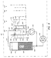
- Figs. 8 and 9 which are common to the embodiment of Fig. 6 received the same reference numerals.
- the Fig. 8 embodiment is a so-called "stand-alone" device which means in the present case that the liquid, in the present case a fixer solution, which is used for regeneration of the ion-exchange resin is not taken from the film processor but instead from a separate tank. Also there is provided a second tank for deceiving the fixer liquid from the device after it has regenerated the resin.
- the device which now will be described is particularly usefull for smaller customers who have only one processor in operation which, moreover, may be under-operated.
- the manually operated three-way valve 156 The manually operated three-way valve 156.
- the volumetric pump 157 (which replaces the former three-way valve 146).
- the volumetric pump 158 for the biocide which replaces the former three pumps 95.
- the three holders 164, 165 and 166 have an identic construction and comprise each a partition wall such as 159 shown for holder 164 (see also Fig. 9) which determines a larger compartment 160 and a smaller compartment 161 in the holder.
- a suitable ratio of the volumes of both compartments is 3 to 1.
- the partition wall has at its bottom a small opening 162 which establishes a fluid communication between both compartments.
- the rear wall 180 of the compartment 161 has an overflow edge 163.
- the rear wall of the first control holder constitutes the front wall of the next one, and so on for the third holder.
- Each resin holder 110, 111 and 112 is in connection with a corresponding control holder via conduits 121, 122 and 123, the conduits ending in an outlet pipe 167 as shown for the holder 164, which has a first and a second branch, resp. 168 and 169.
- the branch 168 extends vertically downwardly to more than half the depth of the holder and ends in a section angled over 90 degrees with opening 177.
- the branch 169 is in fact the horizontal elongation of a T-section and passes liquid-tightly through the partition wail 159.
- the second compartments of the three holders have liquid level sensors 170, 171 and 172 mounted at the same level.
- the first compartment of the first holder further has a liquid sensor 173 mounted at a level between that of the described ones and that of the entrance 181 for the rinsing water received via inlet 45 from the processor.
- the last compartment has a liquid sensor 174 mounted at about two thirds of the level of sensor 172.
- the liquid sensors described hereinbefore may be so-called capacitive proximity sensors which sense the presence of liquid at a distance of some millimeters from their sensing head.
- the device comprises also a microprocessor, not illustrated, which controls the operation of the device, and which may have been programmed to signal to the client the time for regeneration of the resin cartridges on the basis of the type of photographic processor in use and of a predetermined amount of processed film.
- a microprocessor not illustrated, which controls the operation of the device, and which may have been programmed to signal to the client the time for regeneration of the resin cartridges on the basis of the type of photographic processor in use and of a predetermined amount of processed film.
- FIG. 9 there are illustrated in Fig. 9 four different levels 175, 176, 178 and 179 of liquid in the tank, which will be referred to in the following description of the operation of the device.
- rinsing water is received at the inlet 181 of the ion exchange device 20 and flows in the first control holder 164.
- the water leaves the control holder through the outlet 182 of compartment 160 and is pumped by circulation pump 134 into the cartridge 110 with the ion exchange resin 185 via the opening 189.
- the mass of ion exchange resin does not take a position as shown, but rather is urged upwardly until its topside is in contact with the pervious wall 186 of the cartridge 110.
- Rinsing water that leaves the cartridge flows through conduit 121 and pipe 167 to the control holder 164.
- the cross-sections of the branches 168 and 169 are equal to each other, the main part of the liquid will be discharged in compartment 161 and a minor part in compartment 160 since the flow resistance of branch 168 is larger than that of the branch 169 because of the larger back-pressure at the outlet 177 of 168 caused by the larger water column on it.
- the liquid which has been added to the system overflows the edge 163 and enters the adjacent control holder 165 from which the liquid is withdrawn to circulate through the cartridge 111. This process is repeated for the third control holder and corresponding ion-exchange cartridge, and finally an amount of liquid which corresponds with the amount added at 181 is discharged in the compartment 127 from where it flows to the sewer.
- first outlet opening mentioned in the statement of invention is formed in the present arrangement by the opening 177 of the branch 168 whereas the “second outlet opening” is formed by the overflow edge 163 which in practice may be a cut-away portion in the rear wall 180 which on itself may reach as high as the front wall of the control holder.
- the level of the liquid in the holders may vary between the levels 175 and 176.
- the level 176 is that which is determined theoretically by the overflow edge 163, and it is clear that this is the lowest operative level.
- the level 175 results from an addition of liquid to the system which occurs when the film processor starts to evacuate rinsing water upon the addition of fresh water under the control of a sensor which senses the presence of a film to be processed. The difference between both levels depends on the rate of rinsing water; it varied between 2 and 40 mm in the present device, and it will be understood that this difference becomes smaller for the downstream control holders 165 and 166 of the device.
- the flow rate of rinsing water through the resin holders amounted to approximately 13 l.min ⁇ 1. This rate could undergo slight variations in dependence on the condition of the resin.
- the flow rate of the water from the processor was maximum 8 l.min ⁇ 1 so that at rate ratio of at least 13:8, i.e. larger than 1.6 was obtained.
- the intermittent pumping of the circulation pumps 134 to 136 differs in the present device from that of the embodiment of Fig. 6.
- the control of the present device is such that, if during a certain period, which may vary between for instance 5 and 15 minutes, the device did not receive rinsing water from the film processor, the intermittent operation is started whereby the ion-exchange resin gets the opportunity to sink to the bottom of the cartridges and set free deposited gelatin, as described already hereinbefore.
- the initiation of the intermittent operation is signalled as follows.
- the pump 134 continues to withdraw liquid from control holder 164 via opening 182, and said liquid is returned to said holder via the conduit 121.
- the back pressure at branch 169 is smaller than at the outlet 177 of branch 168 so that more liquid is discharged in compartment 161 than in compartment 160. Since the section of the bottom opening 162 is smaller than the section of the branch 169, for instance in a proportion of at least 1 to 3, the liquid in compartment 161 is carried off through opening 162 to compartment 160 at a rate which is smaller than the rate of supply so that liquid is still discharged over the overflow edge 163 although in fact no liquid has been added to the system. The mentioned overflowing of liquid continues until a new equilibrium has been obtained which is at the level 178 obtained after arrestment of the circulation pump. As a matter of fact, once this level has been obtained it is shown that no further liquid is discharged in the next control holder.
- the consequence of the level 178 is that the sensor 173 "sees" no longer liquid so that it is ready for signalling a new supply of rinsing water from the processor that enters through inlet 181 and that flows over the sensor.
- the intermittent operation is started by the operation of pumps 140 to 142 which withdraw liquid from the different control holders and pump it to the sewer via valve 147 and outlet 48' until the level 179, under the control of sensor 174, has been obtained.
- the circulation pumps 134 to 136 are restarted to maintain a circulation of liquid during a certain time, e.g. 10 minutes.
- the described intermittent pumping continues until the sensor 173 signals the arrival again of rinsing water from the processor at entry 181.
- This signal controls the circulation pumps 134 to 136 to stop their intermittent operation, and to operate continuously until a next inactive period of the processor of e.g. 15 minutes has been noticed, whereafter the intermittent operation can restart.
- the input sensor 173 signals no rinsing water during a longer period, for instance during at least 5 hours, this can be taken as an indication that the processor will be out of use for still another number of hours such as at night, which means that the time has come to add biocide to the circuit in order to keep algae growth under control.
- Volumetric pumps 140 to 142 are operated to withdraw an amount of liquid from the circuit until level 179 is obtained (under the control of sensor 174), and next volumetric pump 158 is operated for a preset time period to supply the circuit of each control holder with a pre-determined amount of biocide.
- the outlet ends of the three supply conduits were provided with calibrated nozzles so that in spite of the use of one pump 158 only, it could be ensured that each circuit received the same amount of biocide within narrow tolerances.
- Another way of determining the opportunity of adding biocide may be based on a statistic approach.
- the behaviour of the processor may be recorded during several days in order to find out what is/are the longest rest period(s), and this information may control the addition of the biocide.
- the client manually switches the valve 156 so that rinsing water received from the processor at input 45 now is directly conducted to the sewer via outlet 49.
- the pumps 140 to 142 are operated for a time that is sufficiently long to evacuate all the water from the device via the valve 147 and the outlet 48'.
- pump 157 is operated to fill the three circuits with fresh fixer from a supply tank 185 until the sensor 174 senses the level 179. This level counts only for the third control holder 166, since it will be understood that the first and second control holder will have been completely filled in succession until finally the fixer flows over the overflow edge of the rear wall of holder 165 into the holder 166.
- This reduced level of fixer circuit in the control holders is desirable to avoid at all expense any possible discharge of fixer to the sewer via the end compartment 127, subsequent to the starting of the pumps 134 to 136 which may cause a sudden and relatively large discharge of fixer at the inlet branches such as 169, as described hereinbefore with reference to the intermittent operation of said pump and the related "piston" action.
- the fixer may be removed from the device by pumps 140 to 142 and fed via three-way valve 147 and outlet 47 to a collector tank 188.
- fixer-regeneration may be repeated e.g. five times in order to make the ion-exchange resin ready for another period of operation which may range up to several months.
- the device signals the end of the regeneration, so that the client may switch the valve 156 to reconnect the rinsing circuit of the processor with the inlet 45 of the recovery device.
- the following features may improve the operation of the described device.
- the device may be programmed in such a way that if rinsing water is received from the processor within e.g. one hour after biocide has been added, this addition is considered as nought what means that it will have to be repeated at the first suitable occasion.
- Very limited supplies of rinsing water to the device, separated by relatively long periods, may be disregarded. This is in particular the case for a setting of a processor known as a "jogging program" which in the absence of any film supply during a longer period puts the processor into operation, for instance during one minute for each hour, in order to prevent the formation of liquid stains on film transport roller surfaces, etc.
- the controlling microprocessor may consider a period of more than 24 hours after the last supply of rinsing water to the device as (a) holiday(s), so that no further biocide is added to the device.
- the control may be preferably such that biocide yet is added after an inoperative period of e.g. more than five days.
Landscapes
- Chemical & Material Sciences (AREA)
- Organic Chemistry (AREA)
- Engineering & Computer Science (AREA)
- General Life Sciences & Earth Sciences (AREA)
- Geology (AREA)
- Water Supply & Treatment (AREA)
- Physics & Mathematics (AREA)
- General Physics & Mathematics (AREA)
- Life Sciences & Earth Sciences (AREA)
- Environmental & Geological Engineering (AREA)
- Inorganic Chemistry (AREA)
- Geochemistry & Mineralogy (AREA)
- Chemical Kinetics & Catalysis (AREA)
- Manufacturing & Machinery (AREA)
- Materials Engineering (AREA)
- Mechanical Engineering (AREA)
- Metallurgy (AREA)
- Treatment Of Water By Ion Exchange (AREA)
- Manufacture And Refinement Of Metals (AREA)
- Silver Salt Photography Or Processing Solution Therefor (AREA)
- Photographic Processing Devices Using Wet Methods (AREA)
Claims (21)
- Un dispositif de récupération de l'argent pour la récupération de l'argent à partir de l'eau de lavage d'une développeuse photographique (10) au moyen d'un lit de résine échangeuse d'ions qui est fluidisé par l'eau de lavage, dispositif qui comprend au moins un réservoir à résine échangeuse d'ions (51, 52, 53, 110, 111, 112) muni d'un orifice d'admission de liquide (78, 113, 114, 115, 189) au fond, un premier (74, 128, 169) et un deuxième (79, 129, 163) orifice d'évacuation pour le liquide du réservoir à résine, le deuxième orifice d'évacuation étant situé à un endroit plus haut que le premier, et des moyens de pompage de circulation (134, 135, 136) qui pompent le liquide s'écoulant par le premier orifice d'évacuation vers l'orifice d'admission (78, 113, 114, 115, 189) du réservoir à résine, l'entrée (75, 145, 181) du dispositif se situant à l'ouïe des moyens de pompage de circulation et sa sortie au deuxième orifice d'évacuation (79, 129, 163).
- Un dispositif de récupération de l'argent suivant la revendication 1, qui comprend des moyens de contrôle (97, 150) contrôlant le fonctionnement des moyens de pompage de circulation (134, 135, 136) de façon que ces moyens de pompage sont en marche continue pendant le temps de fonctionnement de la développeuse photographique, et que le fonctionnement des moyens de pompage est intermittent pendant au moins une partie du temps inactif de la développeuse.
- Un dispositif de récupération de l'argent suivant la revendication 1 ou 2, caractérisé en ce qu'au moins deux réservoirs à résine échangeuse d'ions (51, 52, 53, 110, 111, 112) sont montés en série, afin de fonctionner en cascade.
- Un dispositif de récupération de l'argent suivant l'une quelconque des revendications 1 à 3, caractérisé en ce que le premier et le deuxième orifice d'évacuation (74, 79) du dispositif sont constitués dans le réservoir à résine échangeuse d'ions (51, 52, 53).
- Un dispositif de récupération de l'argent suivant l'une quelconque des revendications 1 à 3, caractérisé en ce que le premier et le deuxième orifice d'évacuation (128, 129, 177, 163) du dispositif sont constitués tous les deux dans un réservoir à contrôle séparé (124, 125, 126, 164, 165, 166) qui est lié par une circulation à un réservoir à résine échangeuse d'ions (110, 111, 112), ce réservoir à contrôle étant muni d'une évacuation (137, 138, 139, 182, 183, 184) au fond qui est lié à l'ouïe des moyens de pompage de circulation (134, 135, 136).
- Un dispositif de récupération de l'argent suivant la revendication 5, caractérisé en ce que le premier orifice d'évacuation (128) débouche dans un réservoir à contrôle (124) et est muni de moyens de contrôle qui contrôlent sa fermeture dès que le liquide dans ce réservoir atteint un niveau prédéterminé (148), le premier et le deuxième orifice d'évacuation (128, 129) appartiennent collectivement à une seule conduite d'admission (130), et le deuxième orifice d'évacuation (129) débouche dans un réservoir à contrôle suivant (125) et présente une telle résistance à la circulatior de liquide que le liquide ne commence à s'écouler qu'après que le premier orifice a été fermé.
- Un dispositif de récupération de l'argent suivant la revendication 6, caractérisé en ce que ces moyens de contrôle sont constitués par des moyens sous forme de boules (130) flottant dans le liquide dans le réservoir, ces moyens sous forme de boules et le premier orifice d'évacuation (128) dans ce réservoir étant directement concourants.
- Un dispositif de récupération de l'argent suivant la revendication 6, qui comprend un détecteur de niveau (131) pour le niveau du liquide dans un réservoir à contrôle (126) qui se situe au-dessous de ce niveau prédéterminé (148) dans le réservoir à contrôle et qui contrôle les deuxièmes moyens de pompage (140, 141, 142), pourqu'ils aspirent du liquide du circuit, jusqu'à ce que le niveau dans le réservoir à contrôle baisse jusqu'au-dessous de celui de ce détecteur.
- Un dispositif de récupération de l'argent suivant l'une quelconque des revendications 5 à 8, caractérisé en ce que le réservoir à résine échangeuse d'ions présente la forme d'une cartouche à paquets (110, 111, 112) qui convient pour être raccordée au circuit du liquide du dispositif et pour en être retirée.
- Un dispositif de récupération de l'argent suivant l'une quelconque des revendications 5 à 9, caractérisé en ce que le réservoir à résine échangeuse d'ions (110, 111, 112) convient pour être raccordée en autonome à un circuit de liquide régénérateur de résine.
- Un dispositif de récupération de l'argent suivant la revendication 5, caractérisé en ce qu'un réservoir à contrôle (164, 165, 166) est muni d'une cloison (159) définissant deux compartiments (160, 161 qui sont liés l'un à l'autre à travers une ouverture (162) près du fond de la cloison, le premier orifice d'évacuation (177) étant constitué par la sortie d'une conduite (167) qui s'étend vers le bas dans le premier compartiment, le deuxième orifice d'évacuation étant constitué par un bord de trop-plein (163) du deuxième compartiment (161), et une dérivation (169 de la conduite (167) constituant une liaison entre le premier et le deuxième compartiment à un niveau qui est inférieur à celui du bord de trop-plein (163).
- Un dispositif de récupération de l'argent suivant la revendication 11, caractérisé en ce que la section de l'ouverture (162) dans la cloison (159) s'élève à moins d'un tiers de la section de la dérivation (169) aboutissant dans le deuxième compartiment (161).
- Un dispositif de récupération de l'argent suivant la revendication 11, caractérisé en ce que l'orifice d'évacuation (182, 183, 184) au fond d'un réservoir à contrôle (164, 165, 166) se situe dans le premier compartiment (160) du réservoir.
- Un dispositif de récupération de l'argent suivant les revendications 11 à 13, caractérisé en ce que le taux de la pompe de circulation (134) qui aspire du liquide à travers l'ouverture inférieure (182, 183, 184) d'un réservoir à contrôle, est tel que lors du fonctionnement du dispositif et pendant que la développeuse ne fournit pas d'eau de lavage fraîche, le niveau (178) de liquide dans le premier compartiment (160) soit inférieur au niveau (176) dans le deuxième compartiment (161).
- Un dispositif de récupération de l'argent suivant la revendication 14, caractérisé en ce qu'un détecteur de liquide (173) est installé dans un réservoir à contrôle (164) à telle hauteur qu'il soit au-dessus du niveau (178) de liquide dans le réservoir qui s'établit lorsque la développeuse ne fournit pas d'eau de lavage fraîche, mais à telle hauteur qu'il détecte du liquide, dès que le dispositif reçoit de l'eau de lavage fraîche.
- Un dispositif de récupération de l'argent suivant l'une quelconque des revendications 1 à 15, qui est muni de moyens de vannage pour la régénération en ligne de la résine échangeuse d'ions au moyen de la solution de fixage d'une développeuse photographique qui est pourvue d'un dispositif de récupération de l'argent pour la récupération de l'argent de la solution de fixage.
- Un dispositif de récupération de l'argent suivant la revendication 16, caractérisé en ce que le moment auquel les réservoirs (110, 111, 112) sont raccordés à la résine échangeuse d'ions dans le circuit de fixage de la développeuse photographique, est fixé à base d'une intégration du courant électrique dans le dispositif de récupération de l'argent.
- Un dispositif de récupération de l'argent suivant l'une quelconque des revendications 1 à 15, qui est muni de moyens de vannage et d'un réservoir de liquide régénérateur (187) pour la régénération en autonome de la résine échangeuse d'ions.
- Un dispositif de récupération de l'argent suivant la revendication 18, caractérisé en ce que la régénération de la résine échangeuse d'ions s'effectue après un temps de fonctionnement prédeterminé qui dépend des caractéristiques de la développeuse photographique et du type de fixateur utilisé.
- Un dispositif de récupération de l'argent suivant l'une quelconque des revendications 1 à 19, caractérisé en ce que l'enlèvement de la gélatine qui s'est déposée sur la résine échangeuse d'ions, est favorisé pendant le temps inactif de la développeuse photographique par un réchauffage du liquide dans le dispositif.
- Un dispositif de récupération de l'argent suivant l'une quelconque des revendications 1 à 20, caractérisé en ce que le débit de l'eau de lavage qui passe à travers les réservoirs à résine s'élève à au moins 1,5 fois le débit de l'eau de lavage fournie par une développeuse photographique.
Applications Claiming Priority (4)
| Application Number | Priority Date | Filing Date | Title |
|---|---|---|---|
| EP89202932 | 1989-11-20 | ||
| EP89202932 | 1989-11-20 | ||
| EP90200772 | 1990-03-30 | ||
| EP90200772 | 1990-03-30 |
Publications (2)
| Publication Number | Publication Date |
|---|---|
| EP0430323A1 EP0430323A1 (fr) | 1991-06-05 |
| EP0430323B1 true EP0430323B1 (fr) | 1994-03-02 |
Family
ID=26121378
Family Applications (1)
| Application Number | Title | Priority Date | Filing Date |
|---|---|---|---|
| EP90202985A Expired - Lifetime EP0430323B1 (fr) | 1989-11-20 | 1990-11-12 | Dispositif pour la récupération d'argent |
Country Status (5)
| Country | Link |
|---|---|
| US (1) | US5133846A (fr) |
| EP (1) | EP0430323B1 (fr) |
| JP (1) | JP2620894B2 (fr) |
| DE (1) | DE69007030T2 (fr) |
| DK (1) | DK0430323T3 (fr) |
Families Citing this family (8)
| Publication number | Priority date | Publication date | Assignee | Title |
|---|---|---|---|---|
| DE4031526C2 (de) * | 1990-10-05 | 1997-04-17 | Atotech Deutschland Gmbh | Verfahren zum Ionenaustausch an wässrigen Lösungen mittels Ionenaustauschharzen, sowie Anlage zur Durchführung des Verfahrens |
| US5500125A (en) * | 1994-05-19 | 1996-03-19 | Eastman Kodak Company | Process for recycling photographic wash water |
| EP0699477B1 (fr) * | 1994-09-05 | 1998-07-22 | Agfa-Gevaert N.V. | Dispositif et procédé de récupération d'argent |
| DE19509757C2 (de) * | 1995-03-17 | 2002-09-26 | Eastman Kodak Co | Vorrichtung zum Verbinden einer Filmentwicklungsvorrichtung und einer Silberrückgewinnungseinheit |
| US6422769B1 (en) | 2000-11-03 | 2002-07-23 | Eastman Kodak Company | System and method for processing photographic material which includes wash water recovery |
| US6991669B1 (en) | 2001-06-15 | 2006-01-31 | Chemtronix, Inc. | System and method for silver recovery and monitoring |
| US10807085B2 (en) | 2017-11-17 | 2020-10-20 | University Of Massachusetts | Silver recovery as Ag0nanoparticles from ion-exchange regenerant solution |
| CN115472323B (zh) * | 2022-08-16 | 2024-08-09 | 中核核电运行管理有限公司 | 一种用于核电站一回路系统去除放射性核素110mAg的方法 |
Family Cites Families (11)
| Publication number | Priority date | Publication date | Assignee | Title |
|---|---|---|---|---|
| US3761381A (en) * | 1966-10-18 | 1973-09-25 | A Yagishita | Plating waste recovery unit |
| US4228013A (en) * | 1977-02-01 | 1980-10-14 | De Luxe General, Incorporated | Method and apparatus for recovery of heavy metal ions from dilute aqueous solution |
| DE2741080A1 (de) * | 1977-09-13 | 1979-03-22 | Messner Geb Guth Elfriede | Prinzip der silberrueckgewinnung aus fotofixierbaedern im vollautomatischen durchlaufverfahren |
| DE3034102C2 (de) * | 1980-09-11 | 1985-09-26 | Agfa-Gevaert Ag, 5090 Leverkusen | Vorrichtung zur automatischen Silberrückgewinnung aus silberhaltigen Waschwässern |
| FR2501069B1 (fr) * | 1981-03-05 | 1985-08-02 | Scumra | Procede et dispositif d'extraction d'ions d'un liquide clair ou contenant des matieres en suspension par mise en contact avec un echangeur |
| IT8368114A0 (it) * | 1982-11-02 | 1983-10-26 | Recuperacion De Metales Precio | Dispositivo per la rigenerazione di fissatori fotografici dopo il ricupero dell argento |
| FI71295C (fi) * | 1983-11-18 | 1986-12-19 | Enso Gutzeit Oy | Svaevbaeddsreaktor |
| SE447828B (sv) * | 1984-08-10 | 1986-12-15 | Metall & Bergprodukter Ab | Sett och anordning for att atervinna silver eller liknande ur en vetska innehallande klibbande eller gelebildande emnen |
| US4800005A (en) * | 1987-08-14 | 1989-01-24 | Rosenfield Gerson J | Treatment plant for recovery of metal from hazardous waste |
| JPH0192743A (ja) * | 1987-10-05 | 1989-04-12 | Nanao Kogyo Kk | 写真定着廃液の処理方法 |
| US4855046A (en) * | 1987-10-22 | 1989-08-08 | Napco, Inc. | Multi-canister, externally-connected ion removal system |
-
1990
- 1990-11-12 EP EP90202985A patent/EP0430323B1/fr not_active Expired - Lifetime
- 1990-11-12 DK DK90202985.9T patent/DK0430323T3/da active
- 1990-11-12 DE DE69007030T patent/DE69007030T2/de not_active Expired - Fee Related
- 1990-11-14 US US07/612,854 patent/US5133846A/en not_active Expired - Fee Related
- 1990-11-19 JP JP2315266A patent/JP2620894B2/ja not_active Expired - Lifetime
Also Published As
| Publication number | Publication date |
|---|---|
| EP0430323A1 (fr) | 1991-06-05 |
| DK0430323T3 (da) | 1994-07-04 |
| US5133846A (en) | 1992-07-28 |
| DE69007030T2 (de) | 1994-12-01 |
| DE69007030D1 (de) | 1994-04-07 |
| JPH03188984A (ja) | 1991-08-16 |
| JP2620894B2 (ja) | 1997-06-18 |
Similar Documents
| Publication | Publication Date | Title |
|---|---|---|
| US6696963B2 (en) | Method and system for anticipating salt depletion | |
| JP4844724B2 (ja) | イオン交換装置の制御方法 | |
| US4784763A (en) | Water purification machine | |
| EP0430323A1 (fr) | Dispositif pour la récupération d'argent | |
| US5188732A (en) | Ion exchange resin holder | |
| RU95115513A (ru) | Автоматизированная система для периодического удаления ионов металла из химической ванны, автоматизированная система стабилизации химической ванны, способ удаления ионов металла и система автоматического осаждения покрытия | |
| US20010023841A1 (en) | Controller for salt dosage for a water softener and method of regenerating a water softener | |
| EP0699477A1 (fr) | Dispositif et procédé de récupération d'argent | |
| US4227999A (en) | Ultrafiltration process and apparatus | |
| KR20160135544A (ko) | 금형의 냉각수 관로용 세정기 | |
| JP2778461B2 (ja) | 軟水器の再生制御方法及びその装置 | |
| KR890006157A (ko) | 원료커피에서의 카페인 연속제거용 장치 | |
| JP3725199B2 (ja) | 回分式汚水処理装置 | |
| JP2003511220A (ja) | イオン交換カートリッジの再生装置 | |
| CN111977745B (zh) | 软水机 | |
| US7396455B2 (en) | Brine container with filter system | |
| GB2067598A (en) | Electrolytic recovery of silver | |
| GB2102299A (en) | A regeneration unit for waste water from industrial washing installations | |
| US4346980A (en) | Silver recovery system for X-ray and photographic film processors | |
| CN206082207U (zh) | 一种溶盐罐以及溶盐系统 | |
| JP2795169B2 (ja) | 軟水器の塩水タンクにおける塩水供給量並びに補水量の検出方法 | |
| US4894170A (en) | Liquid recovery system and method | |
| SE445303B (sv) | Sett och apparat for att behandla en blandning av anvenda anjonhartser och katjonhartser | |
| EP0661594A1 (fr) | Appareil de traitement photographique avec une cellule échangeuse d'ions | |
| JP3190768B2 (ja) | 自動製氷機 |
Legal Events
| Date | Code | Title | Description |
|---|---|---|---|
| PUAI | Public reference made under article 153(3) epc to a published international application that has entered the european phase |
Free format text: ORIGINAL CODE: 0009012 |
|
| AK | Designated contracting states |
Kind code of ref document: A1 Designated state(s): BE DE DK FR GB IT |
|
| 17P | Request for examination filed |
Effective date: 19911024 |
|
| 17Q | First examination report despatched |
Effective date: 19920716 |
|
| GRAA | (expected) grant |
Free format text: ORIGINAL CODE: 0009210 |
|
| AK | Designated contracting states |
Kind code of ref document: B1 Designated state(s): BE DE DK FR GB IT |
|
| REF | Corresponds to: |
Ref document number: 69007030 Country of ref document: DE Date of ref document: 19940407 |
|
| ITF | It: translation for a ep patent filed | ||
| REG | Reference to a national code |
Ref country code: DK Ref legal event code: T3 |
|
| ET | Fr: translation filed | ||
| PLBE | No opposition filed within time limit |
Free format text: ORIGINAL CODE: 0009261 |
|
| STAA | Information on the status of an ep patent application or granted ep patent |
Free format text: STATUS: NO OPPOSITION FILED WITHIN TIME LIMIT |
|
| 26N | No opposition filed | ||
| PGFP | Annual fee paid to national office [announced via postgrant information from national office to epo] |
Ref country code: BE Payment date: 19951023 Year of fee payment: 6 |
|
| PGFP | Annual fee paid to national office [announced via postgrant information from national office to epo] |
Ref country code: DK Payment date: 19951108 Year of fee payment: 6 |
|
| PG25 | Lapsed in a contracting state [announced via postgrant information from national office to epo] |
Ref country code: DK Effective date: 19961112 |
|
| REG | Reference to a national code |
Ref country code: DK Ref legal event code: EBP |
|
| PG25 | Lapsed in a contracting state [announced via postgrant information from national office to epo] |
Ref country code: BE Effective date: 19961130 |
|
| REG | Reference to a national code |
Ref country code: GB Ref legal event code: 746 Effective date: 19961118 |
|
| REG | Reference to a national code |
Ref country code: FR Ref legal event code: D6 |
|
| BERE | Be: lapsed |
Owner name: AGFA-GEVAERT N.V. Effective date: 19961130 |
|
| PGFP | Annual fee paid to national office [announced via postgrant information from national office to epo] |
Ref country code: GB Payment date: 19971029 Year of fee payment: 8 |
|
| PGFP | Annual fee paid to national office [announced via postgrant information from national office to epo] |
Ref country code: FR Payment date: 19971030 Year of fee payment: 8 |
|
| PG25 | Lapsed in a contracting state [announced via postgrant information from national office to epo] |
Ref country code: GB Free format text: LAPSE BECAUSE OF NON-PAYMENT OF DUE FEES Effective date: 19981112 |
|
| GBPC | Gb: european patent ceased through non-payment of renewal fee |
Effective date: 19981112 |
|
| PG25 | Lapsed in a contracting state [announced via postgrant information from national office to epo] |
Ref country code: FR Free format text: LAPSE BECAUSE OF NON-PAYMENT OF DUE FEES Effective date: 19990730 |
|
| REG | Reference to a national code |
Ref country code: FR Ref legal event code: ST |
|
| PGFP | Annual fee paid to national office [announced via postgrant information from national office to epo] |
Ref country code: DE Payment date: 20021004 Year of fee payment: 13 |
|
| PG25 | Lapsed in a contracting state [announced via postgrant information from national office to epo] |
Ref country code: DE Free format text: LAPSE BECAUSE OF NON-PAYMENT OF DUE FEES Effective date: 20040602 |
|
| PG25 | Lapsed in a contracting state [announced via postgrant information from national office to epo] |
Ref country code: IT Free format text: LAPSE BECAUSE OF NON-PAYMENT OF DUE FEES;WARNING: LAPSES OF ITALIAN PATENTS WITH EFFECTIVE DATE BEFORE 2007 MAY HAVE OCCURRED AT ANY TIME BEFORE 2007. THE CORRECT EFFECTIVE DATE MAY BE DIFFERENT FROM THE ONE RECORDED. Effective date: 20051112 |