EP0430379B1 - Réacteur chimique - Google Patents
Réacteur chimique Download PDFInfo
- Publication number
- EP0430379B1 EP0430379B1 EP19900203205 EP90203205A EP0430379B1 EP 0430379 B1 EP0430379 B1 EP 0430379B1 EP 19900203205 EP19900203205 EP 19900203205 EP 90203205 A EP90203205 A EP 90203205A EP 0430379 B1 EP0430379 B1 EP 0430379B1
- Authority
- EP
- European Patent Office
- Prior art keywords
- heat
- gas mixture
- receiving body
- catalyst
- receiving
- Prior art date
- Legal status (The legal status is an assumption and is not a legal conclusion. Google has not performed a legal analysis and makes no representation as to the accuracy of the status listed.)
- Expired - Lifetime
Links
Images


Classifications
-
- B—PERFORMING OPERATIONS; TRANSPORTING
- B01—PHYSICAL OR CHEMICAL PROCESSES OR APPARATUS IN GENERAL
- B01J—CHEMICAL OR PHYSICAL PROCESSES, e.g. CATALYSIS OR COLLOID CHEMISTRY; THEIR RELEVANT APPARATUS
- B01J12/00—Chemical processes in general for reacting gaseous media with gaseous media; Apparatus specially adapted therefor
- B01J12/007—Chemical processes in general for reacting gaseous media with gaseous media; Apparatus specially adapted therefor in the presence of catalytically active bodies, e.g. porous plates
-
- B—PERFORMING OPERATIONS; TRANSPORTING
- B01—PHYSICAL OR CHEMICAL PROCESSES OR APPARATUS IN GENERAL
- B01J—CHEMICAL OR PHYSICAL PROCESSES, e.g. CATALYSIS OR COLLOID CHEMISTRY; THEIR RELEVANT APPARATUS
- B01J19/00—Chemical, physical or physico-chemical processes in general; Their relevant apparatus
- B01J19/0006—Controlling or regulating processes
- B01J19/0013—Controlling the temperature of the process
-
- C—CHEMISTRY; METALLURGY
- C01—INORGANIC CHEMISTRY
- C01B—NON-METALLIC ELEMENTS; COMPOUNDS THEREOF; METALLOIDS OR COMPOUNDS THEREOF NOT COVERED BY SUBCLASS C01C
- C01B3/00—Hydrogen; Gaseous mixtures containing hydrogen; Separation of hydrogen from mixtures containing it; Purification of hydrogen; Reversible storage of hydrogen
- C01B3/02—Production of hydrogen; Production of gaseous mixtures containing hydrogen
- C01B3/32—Production of hydrogen; Production of gaseous mixtures containing hydrogen by reaction of gaseous or liquid organic compounds with gasifying agents, e.g. water, carbon dioxide or air
- C01B3/34—Production of hydrogen; Production of gaseous mixtures containing hydrogen by reaction of gaseous or liquid organic compounds with gasifying agents, e.g. water, carbon dioxide or air by reaction of hydrocarbons with gasifying agents
- C01B3/38—Production of hydrogen; Production of gaseous mixtures containing hydrogen by reaction of gaseous or liquid organic compounds with gasifying agents, e.g. water, carbon dioxide or air by reaction of hydrocarbons with gasifying agents using catalysts
- C01B3/384—Production of hydrogen; Production of gaseous mixtures containing hydrogen by reaction of gaseous or liquid organic compounds with gasifying agents, e.g. water, carbon dioxide or air by reaction of hydrocarbons with gasifying agents using catalysts with external heating of the catalyst
-
- B—PERFORMING OPERATIONS; TRANSPORTING
- B01—PHYSICAL OR CHEMICAL PROCESSES OR APPARATUS IN GENERAL
- B01J—CHEMICAL OR PHYSICAL PROCESSES, e.g. CATALYSIS OR COLLOID CHEMISTRY; THEIR RELEVANT APPARATUS
- B01J2219/00—Chemical, physical or physico-chemical processes in general; Their relevant apparatus
- B01J2219/00049—Controlling or regulating processes
- B01J2219/00051—Controlling the temperature
- B01J2219/00121—Controlling the temperature by direct heating or cooling
-
- B—PERFORMING OPERATIONS; TRANSPORTING
- B01—PHYSICAL OR CHEMICAL PROCESSES OR APPARATUS IN GENERAL
- B01J—CHEMICAL OR PHYSICAL PROCESSES, e.g. CATALYSIS OR COLLOID CHEMISTRY; THEIR RELEVANT APPARATUS
- B01J2219/00—Chemical, physical or physico-chemical processes in general; Their relevant apparatus
- B01J2219/00049—Controlling or regulating processes
- B01J2219/00051—Controlling the temperature
- B01J2219/00157—Controlling the temperature by means of a burner
-
- C—CHEMISTRY; METALLURGY
- C01—INORGANIC CHEMISTRY
- C01B—NON-METALLIC ELEMENTS; COMPOUNDS THEREOF; METALLOIDS OR COMPOUNDS THEREOF NOT COVERED BY SUBCLASS C01C
- C01B2203/00—Integrated processes for the production of hydrogen or synthesis gas
- C01B2203/08—Methods of heating or cooling
- C01B2203/0805—Methods of heating the process for making hydrogen or synthesis gas
- C01B2203/0811—Methods of heating the process for making hydrogen or synthesis gas by combustion of fuel
-
- C—CHEMISTRY; METALLURGY
- C01—INORGANIC CHEMISTRY
- C01B—NON-METALLIC ELEMENTS; COMPOUNDS THEREOF; METALLOIDS OR COMPOUNDS THEREOF NOT COVERED BY SUBCLASS C01C
- C01B2203/00—Integrated processes for the production of hydrogen or synthesis gas
- C01B2203/08—Methods of heating or cooling
- C01B2203/0805—Methods of heating the process for making hydrogen or synthesis gas
- C01B2203/0811—Methods of heating the process for making hydrogen or synthesis gas by combustion of fuel
- C01B2203/0816—Heating by flames
-
- C—CHEMISTRY; METALLURGY
- C01—INORGANIC CHEMISTRY
- C01B—NON-METALLIC ELEMENTS; COMPOUNDS THEREOF; METALLOIDS OR COMPOUNDS THEREOF NOT COVERED BY SUBCLASS C01C
- C01B2203/00—Integrated processes for the production of hydrogen or synthesis gas
- C01B2203/08—Methods of heating or cooling
- C01B2203/0805—Methods of heating the process for making hydrogen or synthesis gas
- C01B2203/0866—Methods of heating the process for making hydrogen or synthesis gas by combination of different heating methods
Definitions
- the present invention relates to a chemical reactor which utilises heat to effect the decomposition of a raw gas mixture and is concerned with that type of reactor which has two chambers separated by a partition wall, a porous heat radiating body being disposed in one of the chambers and a porous heat-receiving body in which a catalyst is dispersed being disposed in the other chamber whereby, in use, the heat radiating body is heated by high temperature combustion gas flowing through it and transmits heat to the heat-receiving body which heats a raw gas mixture flowing through it and causes it to react.
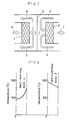
- FIG. 1 A known reactor of the type referred to above is illustrated diagrammatically in Figure 1.
- This reactor comprises a combustion chamber 1 which accommodates a porous heat radiation body 2 and a heat-receiving chamber 3 which accommodates a porous heat-receiving body 4 which carries catalysts uniformly distributed throughout the body and whose pores are of substantially the same diameter throughout.
- the chambers 1 and 3 are separated by a partition wall 5 to prevent gas leakage between them.
- a high-temperature combustion gas 6 obtained by combustion of a fuel flows through the heat radiation body 2 and is then discharged as an exhaust gas 7.
- the combustion gas 6 has sensible heat which is absorbed by convection heat transfer by the heat radiation body 2 during its passage through it so that the heat radiation body 2 is heated and emits radiant heat.
- the radiant heat emitted by the body 2 is received by the heat-receiving body 4 in the form of re-radiated heat from the partition wall 5, if the wall 5 is made of metal or ceramic material or by way of transmission through the wall 5 if the wall 5 is made of transparent material such as quartz glass, whereby the heat-receiving body 4 is heated.
- a raw gas mixture 8 comprising CH4 and H2O passes through the heat-receiving body 4 and is heated and decomposed thereby to produce a generated gas mixture 9 comprising H2 and CO which is discharged out of the chemical reactor.
- the raw gas mixture 8 is thus caused to decompose in the presence of catalysts by the heat of the body 4 which has been radiated to it by the body 2 to obtain the generated gas mixture 9.
- an effective utilisation of heat is achieved and the apparatus for decomposing the raw gas mixture is relatively compact.
- FIG. 2 shows the temperature distributions in the heat radiation body 2 and the heat-receiving body 4 in the chemical reactor described above in the directions of the gas flows.
- the temperature gradient in the heat radiation body 2 is substantially linear
- the temperature gradient in the heat-receiving body 4 is curved and concave downwardly.
- the temperature decreases linearly through the heat radiation body but increases non-linearly at an ever increasing rate in the heat-receiving body 4.
- the temperature is relatively low in the vicinity of the inlet of the body 4 and suddenly rises towards the outlet of the body 4.
- the steam-reforming reaction is endothermic and proceeds slowly at low temperatures and is accelerated with an increase in temperature.
- the steam-reforming reaction does not occur to a significant extent at the low temperature side of the heat-receiving body 4 and mainly occurs at the high temperature side thereof. This means that the absorption of heat by the heat-receiving body 4 occurs at the portion thereof closest to the heat radiation body 2 and effective utilisation of the catalysts is not achieved at the low-temperture portion furthest from the heat radiation body 2.
- a further object of the present invention is to reduce the amount of the expensive catalyst material which is necessary so as to reduce the capital, operational and maintenance costs of the reactor.
- the downstream portion of the heat-receiving body in the direction of flow of the raw gas mixture contains catalyst material dispersed therein and the upstream portion thereof contains no catalyst material.
- the raw gas mixture is initially only heated as it passes through the heat-receiving body and the reaction or decomposition of this mixture then proceeds very rapidly and effectively once it reaches that portion of the heat-receiving body which contains catalyst material. It will be appreciated that this embodiment enables less catalyst material to be used.
- the heat-receiving body is divided into two or more layers in the direction of flow of the raw gas mixture through it, that at least the layer at the downstream end of the body has a catalyst dispersed therein and that at least the layer in the upstream end of the body has no catalyst therein. If the heat-receiving body has only two layers then the downstream layer will have catalyst in it and the upstream layer no catalyst but if there are three layers it is preferred that both the upstream layers have no catalyst in them.
- the porous heat-receiving body 4 has pores of substantially the same diameter throughout and is divided into a plurality, in this case three, heat-receiving layers 4a, 4b and 4c in that order in the direction of the gas flow passing through it. Only the layer 4c nearest to the heat radiation body 2 has catalysts in it while the remaining heat-receiving layers 4a and 4b have no catalyst.
- the raw gas mixture 8 is heated in the layers 4a and 4b and is further heated and also decomposed in the presence of the catalysts in the layer 4c to produce the required generated gas mixture 9.
- the layers 4a and 4b contribute only to the heating of the raw gas mixture 8.
- the endothermic reaction is carried out not in the layers 4a and 4b but only in the layer 4c so that the temperature distribution in the direction of the gas flow in the heat-receiving body 4 is as shown in Figure 4 and the temperature in the vicinity of the raw-gas-mixture inlet of the heat-receiving body 4 is higher than in Figure 2.
- FIG. 5 shows a practical application of the present invention.
- a raw-gas-mixture feed pipe 11 extends centrally into a cylindrical vessel 10 with its lower end open.
- Cylindrical porous heat radiation and heat-receiving bodies 2 and 4 are disposed coaxially around the feed pipe 11.
- a cylindrical partition wall 5 is disposed between the heat radiation and heat-receiving bodies 2 and 4 to define a combustion chamber 1 between the partition wall 5 and the heat radiation body 2 and a heat-receiving chamber 3 between the partition wall 5 and the heat-receiving body 4.
- a burner 12 for supplying fuel and air i.e. a combustion mixture
- An exhaust gas pipe 13 communuicates with the lower portion of the vessel 10 to discharge the exhaust gas 7 after it has passed through the heat radiation body 2.
- a generated-gas outlet pipe 14 communicates with the upper portion of the vessel 10 to discharge the generated gas mixture 9 out of the heat-receiving chamber 3.
- the heat-receiving body 4 is constructed as shown in Figure 3.
- the combustion mixture injected from the burner 12 is burned to produce a high-temperature gas which heats the heat radiation body 2 when the gas flows through it. Radiant heat from the heat radiation body 2 heats the heat-receiving body 4 and the exhaust gas which has flowed through the heat radiation body 2 is discharged through the exhaust pipe 13 to the exterior.
- the raw gas mixture 8 is fed through the feed pipe 11 centrally to the cylindrical vessel 10, heated and decomposed into the generated gas mixture 9 while flowing through the heat-receiving body 4 and is discharged through the outlet pipe 14 to the exterior.
- the raw gas mixture does not necessarily comprise CH4 and H2O and the CH4 may be replaced by other endothermic reaction type gases.
- the catalyst-carrying heat-receiving body is not necessarily disposed in opposing relationship with the heat radiation body, but may be disposed on the side away from the heat radiation body.
- the raw gas mixture may also flow in a direction away from the heat radiation body.
Landscapes
- Chemical & Material Sciences (AREA)
- Chemical Kinetics & Catalysis (AREA)
- Organic Chemistry (AREA)
- Health & Medical Sciences (AREA)
- General Health & Medical Sciences (AREA)
- Engineering & Computer Science (AREA)
- Combustion & Propulsion (AREA)
- Inorganic Chemistry (AREA)
- Devices And Processes Conducted In The Presence Of Fluids And Solid Particles (AREA)
- Hydrogen, Water And Hydrids (AREA)
Claims (2)
- Un réacteur chimique qui possède deux chambres (1, 3) séparées par une paroi d'étanchéité (5), un corps poreux émetteur de chaleur (2) placé dans l'une (1) des chambres et un corps poreux récepteur de chaleur (4), placé dans l'autre chambre (3), dans lequel on a dispersé un catalyseur, grâce à quoi, en mode de fonctionnement, le corps émetteur de chaleur (2) est chauffé par les gaz de combustion à haute température (6) qui le traversent et transmettent la chaleur au corps récepteur de chaleur (4) qui chauffe le mélange de gaz bruts qui le traversent, en forçant ces derniers à réagir, caractérisé en ce que la partie aval (4c) du corps récepteur de chaleur (4), dans le sens de l'écoulement du mélange de gaz bruts, renferme un matériau catalyseur réparti à l'intérieur et
en ce que la partie amont (4a, 4b) ne renferme aucun matériau catalyseur. - Un réacteur selon la revendication 1, caractérisé en ce que le corps récepteur de chaleur (4) est divisé en deux ou plusieurs couches (4a, 4b, 4c) dans le sens de l'écoulement du mélange de gaz bruts qui le traverse, en ce que, au moins la couche (4c), à l'extrémité aval du corps (4), renferme un catalyseur et en ce que la couche (4a), au niveau de l'extrémité amont du corps (4), ne renferme pas de catalyseur.
Applications Claiming Priority (4)
| Application Number | Priority Date | Filing Date | Title |
|---|---|---|---|
| JP17261587A JPS6415132A (en) | 1987-07-10 | 1987-07-10 | Reactor |
| JP172614/87 | 1987-07-10 | ||
| JP172615/87 | 1987-07-10 | ||
| JP17261487A JPH0631352B2 (ja) | 1987-07-10 | 1987-07-10 | 反応装置 |
Related Parent Applications (1)
| Application Number | Title | Priority Date | Filing Date |
|---|---|---|---|
| EP88306274.7 Division | 1988-07-08 |
Publications (2)
| Publication Number | Publication Date |
|---|---|
| EP0430379A1 EP0430379A1 (fr) | 1991-06-05 |
| EP0430379B1 true EP0430379B1 (fr) | 1993-09-15 |
Family
ID=26494917
Family Applications (2)
| Application Number | Title | Priority Date | Filing Date |
|---|---|---|---|
| EP19900203205 Expired - Lifetime EP0430379B1 (fr) | 1987-07-10 | 1988-07-08 | Réacteur chimique |
| EP19880306274 Expired EP0298772B1 (fr) | 1987-07-10 | 1988-07-08 | Réacteur chimique |
Family Applications After (1)
| Application Number | Title | Priority Date | Filing Date |
|---|---|---|---|
| EP19880306274 Expired EP0298772B1 (fr) | 1987-07-10 | 1988-07-08 | Réacteur chimique |
Country Status (2)
| Country | Link |
|---|---|
| EP (2) | EP0430379B1 (fr) |
| DE (2) | DE3884228T2 (fr) |
Families Citing this family (1)
| Publication number | Priority date | Publication date | Assignee | Title |
|---|---|---|---|---|
| GB2264242A (en) * | 1992-02-12 | 1993-08-25 | Johnson Matthey Plc | Heating catalytic converters |
Family Cites Families (3)
| Publication number | Priority date | Publication date | Assignee | Title |
|---|---|---|---|---|
| FR1327210A (fr) * | 1962-04-05 | 1963-05-17 | Soc D Const D App Pour Gaz A L | Appareillage de production de gaz combustible, pour craquage catalytique des hydrocarbures |
| DE3435319A1 (de) * | 1984-09-26 | 1986-04-03 | Michael 4150 Krefeld Laumen | Katalytischer dampferzeuger |
| JPS62210047A (ja) * | 1986-03-10 | 1987-09-16 | Toyo Eng Corp | 反応用装置 |
-
1988
- 1988-07-08 EP EP19900203205 patent/EP0430379B1/fr not_active Expired - Lifetime
- 1988-07-08 DE DE19883884228 patent/DE3884228T2/de not_active Expired - Fee Related
- 1988-07-08 EP EP19880306274 patent/EP0298772B1/fr not_active Expired
- 1988-07-08 DE DE8888306274T patent/DE3867156D1/de not_active Expired - Lifetime
Also Published As
| Publication number | Publication date |
|---|---|
| DE3884228T2 (de) | 1994-01-13 |
| EP0298772A3 (en) | 1989-04-26 |
| EP0298772B1 (fr) | 1991-12-27 |
| DE3867156D1 (de) | 1992-02-06 |
| DE3884228D1 (de) | 1993-10-21 |
| EP0298772A2 (fr) | 1989-01-11 |
| EP0430379A1 (fr) | 1991-06-05 |
Similar Documents
| Publication | Publication Date | Title |
|---|---|---|
| US5449848A (en) | Dehydrogenation process | |
| US4874587A (en) | Hazardous waste reactor system | |
| US4071330A (en) | Steam reforming process and apparatus therefor | |
| CA1308256C (fr) | Recipient utilise pour la production de gaz synthetiques | |
| US4059416A (en) | Chemical reaction process utilizing fluid-wall reactors | |
| SU1075947A3 (ru) | Установка дл проведени эндотермических реакций | |
| EP0360505B1 (fr) | Dispositif de reforming d'hydrocarbure | |
| KR20090004965A (ko) | 고정 베드에서의 흡열 반응을 위한 내부 연소 교환기 반응기 | |
| US3635682A (en) | Fuel cell reactor-burner assembly | |
| JPS62210047A (ja) | 反応用装置 | |
| JPH0123173B2 (fr) | ||
| EP0770269B1 (fr) | Appareil de traitement de combustible ayant un four pour produire un combustible dans une installation pourvue de piles a combustible | |
| JP2508287B2 (ja) | 反応装置 | |
| JP2703831B2 (ja) | 燃料改質器 | |
| EP0298772B1 (fr) | Réacteur chimique | |
| RU2193918C2 (ru) | Способ индукционного поджига химической реакции | |
| US3682605A (en) | Method and apparatus for soot controlling in a thermal decomposition of a hydrocarbon gas | |
| JPH03127A (ja) | 吸熱反応用の反応室における間接的加熱方法およびそれを実施する装置 | |
| JPH0525537B2 (fr) | ||
| JPS5978906A (ja) | 水蒸気改質炉 | |
| JP2733307B2 (ja) | 改質ガス製造装置および方法 | |
| US2718457A (en) | Production of hydrogen cyanide | |
| JP2733308B2 (ja) | 水素を主成分とする改質ガスを製造する装置および方法 | |
| RU2785873C1 (ru) | Способ получения синтез-газа и реактор для получения синтез-газа | |
| JP2733309B2 (ja) | 水素ガスを含有する改質ガスの製造装置および製造法 |
Legal Events
| Date | Code | Title | Description |
|---|---|---|---|
| PUAI | Public reference made under article 153(3) epc to a published international application that has entered the european phase |
Free format text: ORIGINAL CODE: 0009012 |
|
| AC | Divisional application: reference to earlier application |
Ref document number: 298772 Country of ref document: EP |
|
| AK | Designated contracting states |
Kind code of ref document: A1 Designated state(s): DE FR GB |
|
| 17P | Request for examination filed |
Effective date: 19911121 |
|
| RAP1 | Party data changed (applicant data changed or rights of an application transferred) |
Owner name: MITSUBISHI PETROCHEMICAL ENGINEERING CO., LTD. Owner name: MITSUBISHI JUKOGYO KABUSHIKI KAISHA Owner name: RYOKA TECHNO ENGINEERING & CONSTRUCTION CO. Owner name: KABUSHIKI KAISHA TOSHIBA Owner name: CHIYODA CORPORATION Owner name: KABUSHIKI KAISHA KOBE SEIKO SHO Owner name: ISHIKAWAJIMA-HARIMA JUKOGYO KABUSHIKI KAISHA Owner name: TOKYO INSTITUTE OF TECHNOLOGY |
|
| 17Q | First examination report despatched |
Effective date: 19921021 |
|
| GRAA | (expected) grant |
Free format text: ORIGINAL CODE: 0009210 |
|
| AC | Divisional application: reference to earlier application |
Ref document number: 298772 Country of ref document: EP |
|
| AK | Designated contracting states |
Kind code of ref document: B1 Designated state(s): DE FR GB |
|
| REF | Corresponds to: |
Ref document number: 3884228 Country of ref document: DE Date of ref document: 19931021 |
|
| ET | Fr: translation filed | ||
| PLBE | No opposition filed within time limit |
Free format text: ORIGINAL CODE: 0009261 |
|
| STAA | Information on the status of an ep patent application or granted ep patent |
Free format text: STATUS: NO OPPOSITION FILED WITHIN TIME LIMIT |
|
| 26N | No opposition filed | ||
| PGFP | Annual fee paid to national office [announced via postgrant information from national office to epo] |
Ref country code: FR Payment date: 19950621 Year of fee payment: 8 |
|
| PGFP | Annual fee paid to national office [announced via postgrant information from national office to epo] |
Ref country code: GB Payment date: 19950627 Year of fee payment: 8 |
|
| PGFP | Annual fee paid to national office [announced via postgrant information from national office to epo] |
Ref country code: DE Payment date: 19950728 Year of fee payment: 8 |
|
| PG25 | Lapsed in a contracting state [announced via postgrant information from national office to epo] |
Ref country code: GB Effective date: 19960708 |
|
| GBPC | Gb: european patent ceased through non-payment of renewal fee |
Effective date: 19960708 |
|
| PG25 | Lapsed in a contracting state [announced via postgrant information from national office to epo] |
Ref country code: FR Effective date: 19970328 |
|
| PG25 | Lapsed in a contracting state [announced via postgrant information from national office to epo] |
Ref country code: DE Effective date: 19970402 |
|
| REG | Reference to a national code |
Ref country code: FR Ref legal event code: ST |