EP0430389B1 - Gerät zur Herstellung eines Kiesmantels - Google Patents
Gerät zur Herstellung eines Kiesmantels Download PDFInfo
- Publication number
- EP0430389B1 EP0430389B1 EP90305169A EP90305169A EP0430389B1 EP 0430389 B1 EP0430389 B1 EP 0430389B1 EP 90305169 A EP90305169 A EP 90305169A EP 90305169 A EP90305169 A EP 90305169A EP 0430389 B1 EP0430389 B1 EP 0430389B1
- Authority
- EP
- European Patent Office
- Prior art keywords
- wash pipe
- bore
- seal assembly
- packer
- well
- Prior art date
- Legal status (The legal status is an assumption and is not a legal conclusion. Google has not performed a legal analysis and makes no representation as to the accuracy of the status listed.)
- Expired - Lifetime
Links
- 238000012856 packing Methods 0.000 title claims description 53
- 239000004576 sand Substances 0.000 claims description 41
- 239000012530 fluid Substances 0.000 claims description 23
- 238000004519 manufacturing process Methods 0.000 claims description 9
- 238000007789 sealing Methods 0.000 claims description 8
- 239000002002 slurry Substances 0.000 description 5
- 230000015572 biosynthetic process Effects 0.000 description 4
- 210000002445 nipple Anatomy 0.000 description 4
- 238000005406 washing Methods 0.000 description 4
- 241001246312 Otis Species 0.000 description 2
- 239000004568 cement Substances 0.000 description 2
- 238000005086 pumping Methods 0.000 description 2
- 230000000903 blocking effect Effects 0.000 description 1
- 238000004140 cleaning Methods 0.000 description 1
- 238000004891 communication Methods 0.000 description 1
- 238000000034 method Methods 0.000 description 1
- 239000011236 particulate material Substances 0.000 description 1
- 239000007787 solid Substances 0.000 description 1
- 210000001364 upper extremity Anatomy 0.000 description 1
Images


Classifications
-
- E—FIXED CONSTRUCTIONS
- E21—EARTH OR ROCK DRILLING; MINING
- E21B—EARTH OR ROCK DRILLING; OBTAINING OIL, GAS, WATER, SOLUBLE OR MELTABLE MATERIALS OR A SLURRY OF MINERALS FROM WELLS
- E21B33/00—Sealing or packing boreholes or wells
- E21B33/10—Sealing or packing boreholes or wells in the borehole
- E21B33/12—Packers; Plugs
-
- E—FIXED CONSTRUCTIONS
- E21—EARTH OR ROCK DRILLING; MINING
- E21B—EARTH OR ROCK DRILLING; OBTAINING OIL, GAS, WATER, SOLUBLE OR MELTABLE MATERIALS OR A SLURRY OF MINERALS FROM WELLS
- E21B43/00—Methods or apparatus for obtaining oil, gas, water, soluble or meltable materials or a slurry of minerals from wells
- E21B43/02—Subsoil filtering
- E21B43/04—Gravelling of wells
- E21B43/045—Crossover tools
Definitions
- This invention relates to a gravel packing assembly for use in wells, and more particularly to such a system which permits reverse washing of fill encountered as the gravel packing system is run into the well, without tripping the gravel packing system out of the well.
- a known gravel packing system utilized to perform a circulating gravel pack includes a packer and a crossover setting tool associated with the packer for setting the packer and for controlling the flow of fluids during gravel packing operations.
- a gravel packing system When running such a gravel packing system into a well, sometimes sand fill is encountered which has infiltrated into the well and is blocking the passage down through the well. When this occurs, it is necessary to trip the gravel packing system out of the well, and run a clean out string into the well which is capable of reverse circulating the fill out of the well. Then, the gravel packing system must once again be run into the well to perform the gravel packing operation.
- An example of such a gravel packing system is shown in U. S. patent specification No. 4,570,714 (Turner et al). The Turner et al. system utilizes a retrievable packer which is removed from the well with the setting tool after the gravel packing operation is completed.
- US-A-3421586 describes a way in which the problem of sand fill encountered during gravel packing can be overcome without removing the gravel packing string out of the well to allow cleaning.
- This specification uses a conventional gravel packing assembly constructed to be run on a tubing string into a well having a well bore and a well annulus defined between the tubing string and the bore, the assembly comprising an upper packer means for sealing between said tubing string and said well bore to divide said well annulus into an upper well annulus and a lower well annulus above and below said upper packer means, respectively; a crossover setting tool, operably associated with said upper packer means, including crossover valve means for permitting reverse circulation of fluid up through said tubing string during running in of said tubing string and said gravel packing assembly into said well, said setting tool also including a downward extending wash pipe initially communicated with said tubing string; and a screen located below said upper packer means and having said wash pipe extending downwardly therethrough.
- a liner shoe device is attached below the screen and receives
- None of the prior art gravel packing systems have been capable of washing sand fill out of a sump packer without first tripping the work string and gravel packing system out of the well and running a special string into the well for purposes of washing the sand fill.
- a gravel packing assembly as defined above characterised by a sump packer having a bore therethrough; and a wash pipe extension means, located below said screen, for permitting reverse circulation of sand fill out of said sump packer bore up through said wash pipe and said tubing string.
- the wash pipe extension assembly preferably includes an outer seal assembly constructed to be received in the bore of the sump packer.
- the seal assembly has a seal assembly bore defined there through having an upper and a lower end, and the wash pipe of the setting tool extends down into the upper end of the seal assembly bore.
- a wash pipe extension can be partially received in the lower end of the seal assembly bore to extend downward below the seal assembly. The wash pipe extension is communicated with the wash pipe.
- a releasable retaining means is operably associated with the wash pipe and the wash pipe extension for initially retaining the wash pipe extension in the seal assembly bore and for subsequently releasing the wash pipe extension in response to upward movement of the wash pipe relative to the seal assembly.
- the assembly of the invention permits sand fill to be washed from directly above and within the bore of a sump packer by using the wash pipe extension as a stinger which extends into the sump packer bore while reverse circulating the sand fill out of that bore.
- the gravel packing assembly of the present invention can utilise a permanent production packer, and can permit reverse circulating of sand fill encountered during the running in of the system into a well.
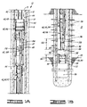
- Figures 1A-1B comprise a sectioned elevational schematic view of one embodiment of gravel packing system of the present invention being run into a well, and having just encountered sand fill above a sump packer. Fluid flow as represented by the arrows is in a reverse circulation mode so that the sand fill is being reverse circulated up through the tubing string.
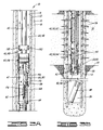
- Figures 2A-2B comprise a view similar to Figures 1A-1B, after the sand fill has been reverse circulated from the sump packer, and the gravel packing assembly has been lowered into sealing engagement with the bore of the sump packer.
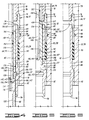
- Figures 3A-3B comprise another view similar to Figures 1A-1B, after the permanent production packer has been set, and the wash pipe has been raised to a position permitting the circulating gravel pack operation to be performed.
- Fluid flow as represented by the arrows shows sand slurry being pumped down the work string, crossing over into the lower annulus to pack sand around the screens, with clean return fluid flowing through the screens and up the wash pipe, then crossing over into the upper annulus for return to the surface.
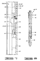
- Figure 4 is a right side only elevational half-section view of an embodiment of wash pipe extension assembly showing the same sealingly received in the sump packer bore in a position corresponding to that of Figure 20, after the sand fill has already been washed from the sump packer, and prior to performing the gravel packing operation.
- Figure 5 is a view similar to Figure 4 wherein the wash pipe has been moved upward relative to the sump packer to a position permitting return flow of clean fluid up through the wash pipe corresponding to the position of Figure 3B.
- the wash pipe extension has been released from the seal assembly bore and has dropped out of the seal assembly and sump packer as schematically represented in Figure 3B wherein the wash pipe extension is shown laying in the sump of the well.
- Figure 6 is a view similar to Figures 4 and 5, after the gravel packing operation has been completed and the crossover setting tool with its wash pipe have been completely pulled out of engagement with the wash pipe extension assembly, thus permitting the support sleeve of the wash pipe extension assembly to also drop out of the sump packer.
- Figure 7 comprises an elevational right side only sectioned view of a portion of a crossover setting tool adjacent the gravel packing ports.
- a crossover valve means is illustrated which controls the flow of fluid through the crossover setting tool.
- the crossover valve means is shown in its initial position in FIG. 7, corresponding to FIG. 1A, wherein flow is permitted up through the wash tube and tubing string and no crossover of fluid is permitted.
- FIG. 8 is an elevational right side only sectioned view of a dart which is a portion of the crossover valve means and which is constructed to be received in the sleeve illustrated in FIG. 7 to subsequently block upward flow through the wash pipe and to open crossover ports to permit the gravel packing operation to be performed.
- FIG. 9 illustrates the dart of FIG. 8 having been received in the sleeve of the setting tool of FIG. 7, with the sleeve having moved down to a position corresponding to that during which the gravel packing operation is performed.
- slurry flows downward through the work string, then into the lower well annulus, then back up through the wash tube and over to the upper well annulus corresponding to the flow previously described with regard to FIG. 3A-3B.
- the well 10 includes a casing 12 which is set within a bore hole 14 and cemented in place by cement 16.
- a bore 13 of casing 12 can generally be referred to as a casing bore 13 or well bore 13.
- the well 10 intersects a subsurface formation 18 from which it is desired to produce oil or gas.
- a sump packer 20 has previously been set within the casing 12 adjacent a lower boundary 22 of formation 18.
- a sump 24 is defined in the well 10 below the sump packer 20.
- the sump packer 20 may also be a sump packer/production packer associated with another producing subsurface formation (not illustrated) located below the sump packer 20.
- the packer 20 will simply be referred to as a sump packer 20, and it will be understood that there may, of course, be other production zones below the packer 20.
- the well Prior to running the gravel packing system described herein into the well 10, the well has been perforated to form perforations such as 26 extending through the casing 12 and cement 16 into the subsurface formation 18 to permit fluids to flow therefrom into the well 10.
- the sump packer 20 includes a sump packer mandrel 28 and a sealing element 30 disposed about the mandrel 28 for sealing against the casing 12.
- a sump packer bore 32 is defined through the mandrel 28.
- the bore 32 has a sums packer bore length 34, and a sump packer bore inside diameter 36.
- An annular locking groove 38 is defined in the sump packer bore 32 for receiving a latch of a seal assembly as further described below.
- a gravel packing assembly is shown and generally designated by the numeral 40.
- the gravel packing assembly 40 is constructed to be run on a tubing string 42 into the well 10.
- a well annulus 44 is defined between the well bore 13 on the outside and the tubing string 42 and gravel packing assembly 40 on the inside.
- the gravel packing assembly 40 generally includes an upper packer means 46, a gravel packer extension 47, a crossover setting tool 48, a screen assembly 50 having a primary screen 52 and a telltale screen 54, and a wash pipe extension assembly 56 suspended from the screen assembly 50.
- the upper packer means 46 is a means for sealing between the tubing string 42 and the well bore 13 to divide the well annulus 44 into an upper well annulus 58 and a lower well annulus 60 above and below the upper packer means 46 (see FIG. 3A).
- the upper packer means 46 is a hydraulically set permanent production packer constructed to be left in place in the well 10 with the screen assembly 50 after the lower well annulus 60 is gravel packed.
- the upper packer means 46 may, for example, be an Otis versa-Trieve (trade mark) gravel packer as manufactured by Otis Engineering Corporation.
- the gravel packer extension 47 extends down from packer means 46 and includes gravel packing ports 49.
- the crossover setting tool 48 is operably associated with the upper packer means 46 for setting the upper packer in a well known manner.
- the crossover setting tool 48 includes crossover valve means 62 for permitting reversing out of sand fill up through the tubing string 42 during running in of the tubing string 42 and gravel packing assembly 40 into a well.
- the operation or crossover valve means 62 is further described below with reference to FIGS. 7-9.
- the crossover setting tool 48 also includes a downward extending wash pipe 64 which is initially communicated with the tubing string 42 through the crossover valve means 62.
- the screen assembly 50 is located below said upper packer means 46 and gravel packer extension 47 and has the wash pipe 64 extending downwardly therethrough in a concentric manner.
- the wash pipe extension assembly 56 which may also generally be referred to as a wash pipe extension means, provides a means for permitting reverse circulation of sand fill out of the sump packer bore 32 up through the wash pipe 64 and tubing string 42.
- a pile of sand fill is schematically illustrated and designated by the numeral 66 on top of the sump packer 20 and inside sump packer bore 32.
- fluid is pumped down the well annulus 44 as indicated by arrows.
- the fluid flow turns upward into a lower end 68 of the wash pipe extension assembly 56.
- the fluid, carrying entrained sand from sand fill 66, then flows up the wash pipe 64 and up the tubing string 42 as indicated by the arrows, to the surface.
- Wash pipe extension assembly 56 is best shown in FIG. 4 in combination with a lower portion 70 of wash pipe 64.
- Wash pipe extension assembly 56 includes an outer seal assembly 72 constructed to be sealingly received in the sump packer bore 32.
- the outer seal assembly 72 includes an upper box end 74 threadedly connected at 76 to a pin end 78 extending downward from telltale screen 54.
- Outer seal assembly 72 further includes a cylindrical body 80 threadedly connected to box end 74 at thread 82.
- a plurality of flexible locater arms 84 extend downward From box end 74 about an outer surface 86 of body 80.
- the locater arms 84 each have an outward extending ridge 88 which snaps into place in locking groove 38 of sump packer mandrel 28.
- An annular sealing member 90 is disposed about outer surface 86 of body 80 and is sealingly engaged with the sump packer bore 32.
- the wash pipe extension means 56 is shown sealingly latched in place within the sump packer bore 32 as it is in FIG. 2B, after the sand fill 66 has been washed away from the sump packer 20.
- the outer seal assembly 72 has a seal assembly bore 92 extending therethrough having an upper end 94 and a lower end 96.
- the lower portion 70 of wash pipe 64 extends down into the upper end 94 of seal assembly bore 92.
- a wash pipe extension 98 is partially received in the lower end 96 of seal assembly bore 92 and extends downward a distance 100 (see FIG. 1B) below the lower end 96 of seal assembly 72.
- the wash pipe extension 98 has an inner bore 102 which is communicated with an inner bore 104 of wash pipe 64.
- a releasable retaining means is operably associated with the wash pipe 64 and the wash pipe extension 98 for initially retaining the wash pipe extension 98 in place in the seal assembly bore 92 as illustrated in FIG. 4, and for subsequently releasing the wash pipe extension 98 in response to upward movement of the wash pipe 64 relative to the seal assembly 72 as shown in FIG. 5. This allows the wash pipe extension 98 to drop out of the seal assembly bore 92 and fall down into the sump 24 as schematically illustrated in FIG. 3B.
- the distance 100 by which the wash pipe extension 98 extends below the seal assembly 72 is greater than the length 34 of the sump packer bore 32.
- the wash pipe extension 98 has an outside diameter 108 (see FIG. 1B) substantially less than the diameter 36 of sump packer bore 32. This permits reversing out of the sand fill 66 from the sump packer bore 32 because it permits fluid to flow down through the well annulus 44 and then downward through an annular space between the outside diameter 108 of wash pipe extension 98 and the inside diameter 36 of sump packer bore 32 to wash the sand fill 66 out of sump packer bore 32 as the wash pipe extension 98 slowly moves downward into the sump packer bore 32. Since the wash pipe extension 98 extends downward by a length 100 greater than the length 34 of sump packer bore 32, this relatively long, relatively small diameter wash pipe extension 98 can wash out sand fill 66 from the entire length of sump packer bore 32.
- the outside diameter 108 of wash pipe extension 98 should be about 2.3 inches (5.84 cm).
- the sump packer 20 will often have a nipple 110 connected to the lower end of sump packer mandrel 28 for receiving a plug (not shown).
- the wash pipe extension 98 should have a length sufficient also to wash out the nipple 110. If there is a plug located within the nipple 110, the same can be pushed out of the nipple 110 by exerting downward force thereon with the wash pipe extension 98 simply by setting down weight on the working string 42.
- the releasable retaining means 106 includes a radially inwardly biased first spring collet 112 defined on the upper end of the wash pipe extension 98.
- the first spring collet 112 includes a plurality of spring fingers such as 114 and 116. Each of the spring fingers has a radially outward extending shoulder 118 defined thereon.
- the releasable retaining means 106 also includes an upwardly facing annular latching surface or shoulder 120 defined on the seal assembly bore 92.
- Releasable retaining means 106 further includes a support means 122 which can also be referred to as a support sleeve 122, for initially retaining the shoulders 118 of the first spring collet 112 in engagement with the annular latching surface 120 of seal assembly bore 92.
- the support sleeve 122 has an outer cylindrical surface 124 which is closely and slidably received within the seal assembly bore 92 with a sliding O-ring seal 126 being provided therebetween.
- the support sleeve 122 has a reduced outside diameter lower sleeve portion or skirt 128 which is initially concentrically disposed within the upper end of first spring collet 112 to prevent the spring fingers such as 114 and 116 from springing inward This holds the shoulders 118 in engagement with the latching surface 120 so as to initially hold the wash pipe extension 98 in place within the outer seal assembly 72.
- the gravel packing assembly 40 further includes a second release means 130 operably associated with the wash pipe 64 and with the outer seal assembly 72 for releasing the support sleeve 122 from engagement with the wash pipe 64 after the wash pipe extension 98 is released from the seal assembly 72 and for permitting the support sleeve 122 to then also drop out of the seal assembly bore 92.
- the second release means 130 includes an annular downward facing surface 132, which may also be referred to as a limit means 132, defined in the seal assembly bore 92 above the support sleeve 122, for limiting upward movement of support sleeve 122 within the seal assembly bore 92.
- the second release means 130 also includes a second spring collet 134 defined on the lower end portion 70 of wash pipe 64.
- the second spring collet 134 includes a plurality of downward extending collet fingers 136 having enlarged heads 138 thereon which initially latch under a tapered lower end surface 140 of support sleeve 122.
- the enlarged heads 138 and the lower end 140 of support sleeve 122 form an interconnection means 142 between the support sleeve 122 and the wash pipe 64 for moving the support sleeve 122 upward with the wash pipe 64 when the wash pipe 64 is moved upward relative to the outer seal assembly 72.
- first spring collet 112 spring inward moving the shoulders 118 out of engagement with the annular latching surface 120, and the wash pipe extension 98 drops out of the seal assembly bore 92 leaving the other components in the position generally illustrated in FIG. 5.
- the lower end portion 70 of wash pipe 64 has a plurality of lateral ports 148 disposed therethrough.
- Upper and lower O-ring seals 150 and 152 are located in annular grooves above and below the ports 148 in the wash pipe 64.
- the O-rings 150 and 152 seal against the bore 146 of support sleeve 122 for initially preventing flow of fluids through the lateral ports 148 until such time as the wash pipe 64 is moved upward as shown in FIG. 5.
- a fully open sump packer bore is desirable for several reasons. If there are lower production zones below sump packer 20 it may be necessary to run tools down through the sump packer 20. Also, it is desirable to have an open bore so that any solid particulate materials produced from the well will not collect on top of the sump packer.
- FIGS. 7-9 the crossover valve means 62 will be further described.
- the crossover valve means 62 provides a means for permitting reverse circulation of fluid up through the tubing string 42 while running the tubing string 42 into the well, as schematically illustrated in FIGS. 1A-1B.
- the crossover valve means 62 also provides a means for subsequently isolating the wash pipe 64 from the tubing string 42 and for communicating the wash pipe 64 with the upper well annulus 58 and for communicating the tubing string 42 with the lower well annulus 60 to permit gravel packing of the lower well annulus 60 with the flow paths being as schematically illustrated in FIGS. 3A-3B.
- FIG. 7 is an enlarged detailed view of a lower portion 156 of the crossover setting tool 48 which extends down through the upper packer means 46 and the gravel packer extension 47. It will be understood that in FIG. 7, the surrounding structure of the upper packer means 46, the gravel packer extension 47 and the well 10 have not been shown in order to simplify the illustration.
- crossover setting tool 48 includes a crossover body 158 having inner and outer con centric walls 160 and 162 defining an annular flow space 164 therebetween.
- the inner concentric wall 160 has an inner bore 166 within which is received a sliding sleeve 168 which is a portion of the crossover valve means 62.
- a plurality of radially extending lower crossover ports 170 extend radially outward from and communicate with the bore 166 of inner wall 160.
- Crossover ports 170 communicate with gravel packing ports 49 as seen in FIG. 3A.
- the sleeve 168 is initially pinned in place by shear pins 172 in a position closing the lower crossover ports 170. As is further described below, the sleeve 168 will subsequently be moved downward uncovering the lower crossover ports 170 so as to provide fluid communication between the tubing string 42 and the lower well annulus 60.
- the ports 170 are referred to as lower crossover ports because they are associated with the lower well annulus 60.
- a dart 174 shown in FIG. 8 is dropped or pumped down the tubing string 42 into engagement with the sleeve 160.
- a tapered shoulder 176 of dart 174 seats in a tapered annular seat 178 of sleeve 160.
- a pair of O-ring seals 180 seal between the dart 174 and an enlarged diameter upper bore 182 of sleeve 168.
- a lower bore 188 of outer wall 164 is communicated with the bore 104 of wash pipe 64.
- the sleeve 168 includes a plurality of upper crossover ports 190 which provide a means for communicating the wash pipe 64 with the upper well annulus 58.
- the upper crossover ports 190 are communicated with the annular flow space 164 which communicates with other passages extending upward through the crossover setting tool 48 terminating in an upper crossover outlet 192 schematically shown in FIG. 3A thus communicating the wash pipe 64 with the upper well annulus 58.
- the dart 174 has a hollow lower portion which has inlets 194, a bore 196 and outlets 198 which communicate the lower bore 188 and wash pipe 64 with the upper crossover ports 190 in the position of FIG. 9.
- a ball check valve 200 is disposed in the bore 196 and seats on a conical annular seat 202 to prevent downward flow therethrough when the dart 174 is positioned as shown in FIG. 9.
- An O-ring seal 204 seals between the bore 166 of inner wall 158 and the sleeve 122 above the upper crossover ports 190.
- the gravel packing assembly 40 is supported from the tubing string 42, and then the tubing string 42 and gravel packing assembly 40 are run into the well 10 until a sand fill such as sand fill 66 is encountered. It will be appreciated that sand fill may be encountered at various locations throughout the well in addition to immediately adjacent and within the sump packer 20.
- the sand fill Upon encountering sand fill, the sand fill is reverse washed from the well 10 by pumping fluid down through the well annulus 44 and up through the wash pipe 64 and tubing string 42 as is schematically illustrated in FIGS. 1A-1B. Once all of the sand fill is eliminated, two tubing volumes of fluid are reverse circulated to make certain that the sand is removed from the system.
- the tubing string 42 is run further into the well 10 until the gravel packing assembly 40 is located at a desired preselected location.
- the desired prese lected location is that in which the wash pipe extension assembly 56 is positioned within the sump packer 20 as schematically illustrated in FIGS. 2A-2B.
- the dart 174 is dropped to set the packer 46 and to operate the sleeve 168 moving it to its lowermost position as shown in FIG. 9, thus communicating the tubing string 42 with the lower well annulus 60 and communicating the wash pipe 64 with the upper well annulus 58.
- the wash pipe 64 is moved upward relative to the screen assembly 50 with the screen assembly 50 and the permanent production packer 46 fixed in place within the well 10, until the wash pipe 64 is communicated with the interior of the screen assembly 50, as is schematically illustrated in FIGS. 3A-3B and as is illustrated in FIG. 5.
- the lower well annulus 60 is gravel packed by pumping sand slurry down the tubing string 42, out the lower crossover ports 170, into the lower well annulus 60.
- the sand from the slurry will build up in the lower well annulus 60 around the screen assembly 50 and clean fluid from the slurry will enter the screen assembly 50 and flow up the wash pipe 64, then through the upper crossover ports 190 and up through the annular flow space 164 and ultimately out the upper crossover outlet 192 and then up through the upper well annulus 58.
Landscapes
- Life Sciences & Earth Sciences (AREA)
- Engineering & Computer Science (AREA)
- Geology (AREA)
- Mining & Mineral Resources (AREA)
- Physics & Mathematics (AREA)
- Environmental & Geological Engineering (AREA)
- Fluid Mechanics (AREA)
- General Life Sciences & Earth Sciences (AREA)
- Geochemistry & Mineralogy (AREA)
- Earth Drilling (AREA)
Claims (10)
- Eine Kiesschüttanordnung (40), die zum Einführen an einem Rohrstrang (42) in eine Bohrung (10) konstruiert ist, mit einer Innenbohrung (13) und einem Bohrungsringraum (44), der zwischen dem besagten Rohrstrang und der besagten Innenbohrung abgegrenzt ist, umfassend: ein oberes Packermittel (46) zum Abdichten des Raumes zwischen dem besagten Rohrstrang und der besagten Innenbohrung zwecks Unterteilung des besagten Bohrungsringraums in einen oberen Bohrungsringraum (58) und einen unteren Bohrungsringraum (60) oberhalb bzw. unterhalb des besagten oberen Packermittels; ein Überleitsetzwerkzeug (48), das auf für Betrieb geeignete Weise mit dem besagten oberen Packermittel in Verbindung steht, einschließlich eines Überleitventilmittels (62), um während des Einführens des besagten Rohrstrangs und der besagten Kiesschüttanordnung in die besagte Bohrung durch den besagten Rohrstrang hindurch Gegenstromumlauf von Flüssigkeit zu gestatten, wobei das besagte Setzwerkzeug auch ein sich nach unten erstreckendes Spülrohr (64) umfaßt, das sich anfänglich mit dem besagten Rohrstrang in Kommunikation befindet; und ein Sieb (50), das unterhalb des besagten oberen Packermittels angeordnet ist und durch das sich das besagte Spülrohr abwärts erstreckt: gekennzeichnet durch einen Sumpfpacker (20) mit einer durch diesen hindurch führenden Bohrung (32); sowie durch ein Spülrohrverlängerungsmittel (56), das unterhalb des besagten Siebs angeordnet ist, um Gegenstromumlauf von Schüttsand aus der besagten Sumpfpackerbohrung durch das besagte Spülrohr und den besagten Rohrstrang nach oben hin zu gestatten.
- Eine Anordnung nach Anspruch 1, bei der das besagte Überleitventilmittel (62) des besagten Setzwerkzeugs (48) so betrieben werden kann, daß es das besagte Spülrohr (64) von dem besagten Rohrstrang (42) trennt und zwischen dem besagten Spülrohr und dem besagten oberen Bohrungsringraum (58) sowie zwischen dem besagten Rohrstrang und dem besagten unteren Bohrungsringraum (60) Kommunikation bewirkt, um das Einschütten von Kies in dem besagten unteren Bohrungsringraum zu ermöglichen.
- Eine Anordnung nach Anspruch 1 oder 2, bei der das besagte Spülrohrverlängerungsmittel (56) eine äußere Dichtungsgruppe (72) umfaßt, die infolge ihrer Bauweise in der besagten Sumpfpackerbohrung (32) Aufnahme findet, wobei in der besagten Dichtungsgruppe eine durch sie hindurch verlaufende Dichtungsgruppenbohrung (92) vorgesehen ist, und zwar hat die besagte Dichtungsgruppenbohrung ein oberes Ende (94) und ein unteres Ende (96), während sich das besagte Spülrohr des besagten Setzwerkzeugs in das besagte obere Ende der besagten Dichtungsgruppenbohrung erstreckt;
eine teilweise in dem besagten unteren Ende der besagten Dichtungsgruppenbohrung Aufnahme findende Spülrohrverlängerung (98), die sich in Abwärtsrichtung unterhalb der besagten Dichtungsgruppe erstreckt, wobei zwischen der besagten Spülrohrverlängerung und dem besagten Spülrohr Kommunikation besteht; und
ein auslösbares Haltemittel (106), das mit dem besagten Spülrohr (64) und der besagten Spülrohrverlängerung (98) auf für Betrieb geeignete Weise verbunden ist, um die besagte Spülrohrverlängerung anfänglich in der besagten Dichtungsgruppenbohrung festzuhalten und danach die besagte Spülrohrverlängerung bei Aufwärtsbewegung des besagten Spülrohrs im Verhältnis zu der besagten Dichtungsgruppe freizugeben. - Eine Anordnung nach Anspruch 3, bei der sich die besagte Spülrohrverlängerung (98) um eine Distanz, die größer ist als die Länge der Sumpfpackerbohrung (32), unterhalb der besagten Dichtungsgruppe (72) erstreckt, und die besagte Spülrohrverlängerung einen Außendurchmesser hat, der geringer ist als der Innendurchmesser der Sumpfpackerbohrung, so daß während des Rückspülens von Schüttsand von dem besagten Sumpfpacker (20) Flüssigkeit zwischen der besagten Sumpfpackerbohrung und der besagten Spülrohrverlängerung abwärts und dann in ein unteres Ende der besagten Spülrohrverlängerung aufwärts fließen kann, um den besagten Schüttsand innerhalb der gesamten besagten Länge der besagten Sumpfpackerbohrung aus der besagten Sumpfpackerbohrung zu spülen; und
bei der das besagte auslösbare Haltemittel (106) so angeordnet ist, daß es die besagte Spülrohrverlängerung von der besagten Dichtungsgruppenbohrung freigibt, wenn die besagte Spülrohrverlängerung freigegeben wird. - Eine Anordnung nach Anspruch 3 oder 4, bei der das besagte auslösbare Haltemittel (106) eine radial einwärts vorgespannte erste Federspannzange (112) umfaßt, die an einem oberen Ende der besagten Spülrohrverlängerung (98) vorgesehen ist, wobei die besagte erste Federspannzange eine Mehrzahl von federbelasteten Fingern (114, 116) umfaßt, während an jedem von den besagten Fingern eine sich radial nach außen erstreckende Schulter (118) vorgesehen ist;
eine nach oben gerichtete Feststellfläche (120), die an der besagten Dichtungsgruppenbohrung (92) vorgesehen ist; und
Abstützmittel (122) für anfängliche Halterung der besagten Schultern der besagten ersten Federspannzange in Eingriff mit der besagten Feststellfläche der besagten Dichtungsgruppenbohrung. - Eine Vorrichtung nach Anspruch 5, bei der das besagte Abstützmittel (122) eine verschiebbar innerhalb der besagten Dichtungsgruppenbohrung (92) angeordnete Abstützhülse ist, wobei die besagte Abstützhülse eine Hülsenbohrung umfaßt, in der ein unterer Endabschnitt (70) des besagten Spülrohrs Aufnahme findet, während die besagte Abstützhülse einen unteren Hülsenabschnitt (128) besitzt, der anfänglich konzentrisch innerhalb der besagten ersten Federspannzange (112) angeordnet ist.
- Eine Anordnung nach Anspruch 6, bei der der besagte untere Endabschnitt (70) des besagten Spülrohrs (64) eine durch diesen hindurch führende seitliche Öffnung (148) besitzt; und
die besagte Kiesschüttanordnung des weiteren zwischen dem besagten unteren Abschnitt des besagten Spülrohrs und der Hülsenbohrung angeordnete Dichtungsmittel (150, 152) umfaßt, um anfänglich Durchfluß durch die besagte seitliche Öffnung hindurch zu verhindern, bis das besagte Spülrohr im Verhältnis zu der besagten Dichtungsgruppe aufwärtsbewegt wird. - Eine Anordnung nach Anspruch 5, 6 oder 7, die des weiteren Auslösemittel (130) zum Freigeben der besagten Abstützhülse (122) von dem besagten Spülrohr (64), nachdem die besagte Spülrohrverlängerung (98) von der besagten Dichtungsgruppe freigegeben wurde, umfaßt; und zum Freigeben der besagten Abstützhülse (122) von der besagten Dichtungsgruppenbohrung.
- Eine Anordnung nach Anspruch 8, bei der das besagte Auslösemittel (130) eine zweite Federspannzange (134) umfaßt, die an dem besagten unteren Endabschnitt (70) des besagten Spülrohrs (64) vorgesehen ist, wobei die besagte zweite Federspannzange vergrößerte Köpfe (138) hat, die anfänglich unter einem unteren Ende (140) der besagten Abstützhülse (122) eingreifen, wobei die besagte zweite Federspannzange so beschaffen ist, daß sie zusammenklappt und durch die besagte Abstützhülse hindurch zieht.
- Eine Anordnung nach einem der Ansprüche 1 bis 9, bei der es sich bei dem besagten oberen Packermittel (46) um ein permanentes Förderungspackermittel handelt, das für Belassung gemeinsam mit dem besagten Sieb in der besagten Bohrung, nachdem Kies in dem besagten unteren Bohrungsringraum eingeführt wurde, gebaut ist.
Applications Claiming Priority (2)
| Application Number | Priority Date | Filing Date | Title |
|---|---|---|---|
| US441786 | 1989-11-27 | ||
| US07/441,786 US4944348A (en) | 1989-11-27 | 1989-11-27 | One-trip washdown system and method |
Publications (2)
| Publication Number | Publication Date |
|---|---|
| EP0430389A1 EP0430389A1 (de) | 1991-06-05 |
| EP0430389B1 true EP0430389B1 (de) | 1994-07-13 |
Family
ID=23754274
Family Applications (1)
| Application Number | Title | Priority Date | Filing Date |
|---|---|---|---|
| EP90305169A Expired - Lifetime EP0430389B1 (de) | 1989-11-27 | 1990-05-14 | Gerät zur Herstellung eines Kiesmantels |
Country Status (7)
| Country | Link |
|---|---|
| US (1) | US4944348A (de) |
| EP (1) | EP0430389B1 (de) |
| AU (1) | AU5492690A (de) |
| BR (1) | BR9003872A (de) |
| CA (1) | CA2016662A1 (de) |
| DE (1) | DE69010635T2 (de) |
| NO (1) | NO902005D0 (de) |
Cited By (3)
| Publication number | Priority date | Publication date | Assignee | Title |
|---|---|---|---|---|
| US8220542B2 (en) | 2006-12-04 | 2012-07-17 | Schlumberger Technology Corporation | System and method for facilitating downhole operations |
| US8245782B2 (en) | 2007-01-07 | 2012-08-21 | Schlumberger Technology Corporation | Tool and method of performing rigless sand control in multiple zones |
| US8496055B2 (en) | 2008-12-30 | 2013-07-30 | Schlumberger Technology Corporation | Efficient single trip gravel pack service tool |
Families Citing this family (41)
| Publication number | Priority date | Publication date | Assignee | Title |
|---|---|---|---|---|
| US5174379A (en) * | 1991-02-11 | 1992-12-29 | Otis Engineering Corporation | Gravel packing and perforating a well in a single trip |
| US5413180A (en) * | 1991-08-12 | 1995-05-09 | Halliburton Company | One trip backwash/sand control system with extendable washpipe isolation |
| US5343949A (en) * | 1992-09-10 | 1994-09-06 | Halliburton Company | Isolation washpipe for earth well completions and method for use in gravel packing a well |
| US5597040A (en) * | 1994-08-17 | 1997-01-28 | Western Company Of North America | Combination gravel packing/frac apparatus for use in a subterranean well bore |
| US5775421A (en) * | 1996-02-13 | 1998-07-07 | Halliburton Company | Fluid loss device |
| US5735345A (en) * | 1996-05-02 | 1998-04-07 | Bestline Liner Systems, Inc. | Shear-out landing adapter |
| US5845712A (en) * | 1996-12-11 | 1998-12-08 | Halliburton Energy Services, Inc. | Apparatus and associated methods for gravel packing a subterranean well |
| US6241013B1 (en) * | 1998-08-25 | 2001-06-05 | Halliburton Energy Services, Inc. | One-trip squeeze pack system and method of use |
| US6220370B1 (en) | 1999-02-18 | 2001-04-24 | Owen Oil Tools, Inc. | Circulating gun system |
| US6286598B1 (en) | 1999-09-29 | 2001-09-11 | Halliburton Energy Services, Inc. | Single trip perforating and fracturing/gravel packing |
| US6883605B2 (en) | 2002-11-27 | 2005-04-26 | Offshore Energy Services, Inc. | Wellbore cleanout tool and method |
| EP1570154A4 (de) * | 2002-12-12 | 2006-05-03 | Albert August Mullins | Bohrlochreinigung und röhrenförmige zirkulations- und rückstromvorrichtung |
| WO2005103440A2 (en) * | 2004-04-27 | 2005-11-03 | Schlumberger Canada Limited | Deploying an assembly into a well |
| US7367395B2 (en) * | 2004-09-22 | 2008-05-06 | Halliburton Energy Services, Inc. | Sand control completion having smart well capability and method for use of same |
| US7461695B2 (en) * | 2005-04-01 | 2008-12-09 | Schlumberger Technology Corporation | System and method for creating packers in a wellbore |
| US8267173B2 (en) * | 2009-05-20 | 2012-09-18 | Halliburton Energy Services, Inc. | Open hole completion apparatus and method for use of same |
| US8689891B2 (en) * | 2011-04-29 | 2014-04-08 | Vetco Gray Inc. | Ball and dart launcher with parallel axis release |
| US9238953B2 (en) * | 2011-11-08 | 2016-01-19 | Schlumberger Technology Corporation | Completion method for stimulation of multiple intervals |
| US9650851B2 (en) | 2012-06-18 | 2017-05-16 | Schlumberger Technology Corporation | Autonomous untethered well object |
| US9631468B2 (en) | 2013-09-03 | 2017-04-25 | Schlumberger Technology Corporation | Well treatment |
| US9488039B2 (en) * | 2014-07-03 | 2016-11-08 | Baker Hughes Incorporated | Multi-zone single treatment gravel pack system |
| US20180252053A1 (en) * | 2017-03-06 | 2018-09-06 | Saudi Arabian Oil Company | Mono-bore wellbore completion with a retrievable portion |
| US10316619B2 (en) | 2017-03-16 | 2019-06-11 | Saudi Arabian Oil Company | Systems and methods for stage cementing |
| US10544648B2 (en) | 2017-04-12 | 2020-01-28 | Saudi Arabian Oil Company | Systems and methods for sealing a wellbore |
| US10557330B2 (en) | 2017-04-24 | 2020-02-11 | Saudi Arabian Oil Company | Interchangeable wellbore cleaning modules |
| US10487604B2 (en) | 2017-08-02 | 2019-11-26 | Saudi Arabian Oil Company | Vibration-induced installation of wellbore casing |
| US10378298B2 (en) | 2017-08-02 | 2019-08-13 | Saudi Arabian Oil Company | Vibration-induced installation of wellbore casing |
| US10597962B2 (en) | 2017-09-28 | 2020-03-24 | Saudi Arabian Oil Company | Drilling with a whipstock system |
| US10378339B2 (en) | 2017-11-08 | 2019-08-13 | Saudi Arabian Oil Company | Method and apparatus for controlling wellbore operations |
| US10689914B2 (en) | 2018-03-21 | 2020-06-23 | Saudi Arabian Oil Company | Opening a wellbore with a smart hole-opener |
| US10689913B2 (en) | 2018-03-21 | 2020-06-23 | Saudi Arabian Oil Company | Supporting a string within a wellbore with a smart stabilizer |
| US10794170B2 (en) | 2018-04-24 | 2020-10-06 | Saudi Arabian Oil Company | Smart system for selection of wellbore drilling fluid loss circulation material |
| US10612362B2 (en) | 2018-05-18 | 2020-04-07 | Saudi Arabian Oil Company | Coiled tubing multifunctional quad-axial visual monitoring and recording |
| CN110159342B (zh) * | 2019-06-12 | 2024-07-23 | 中国石油大学(北京) | 砾石充填模拟实验系统 |
| CN111155991B (zh) * | 2020-02-25 | 2023-06-27 | 东北石油大学 | 模拟隔层胶结差地层的可分离双层耐压填砂管及模拟方法 |
| US11299968B2 (en) | 2020-04-06 | 2022-04-12 | Saudi Arabian Oil Company | Reducing wellbore annular pressure with a release system |
| CN111706304B (zh) * | 2020-07-01 | 2022-08-30 | 杨国 | 一种具有反循环功能的充填工具 |
| US11396789B2 (en) | 2020-07-28 | 2022-07-26 | Saudi Arabian Oil Company | Isolating a wellbore with a wellbore isolation system |
| US11414942B2 (en) | 2020-10-14 | 2022-08-16 | Saudi Arabian Oil Company | Packer installation systems and related methods |
| US11624265B1 (en) | 2021-11-12 | 2023-04-11 | Saudi Arabian Oil Company | Cutting pipes in wellbores using downhole autonomous jet cutting tools |
| US12448862B1 (en) * | 2024-04-23 | 2025-10-21 | Brett Olson | All in one remedial tool |
Family Cites Families (11)
| Publication number | Priority date | Publication date | Assignee | Title |
|---|---|---|---|---|
| US2755862A (en) * | 1951-10-24 | 1956-07-24 | Exxon Research Engineering Co | Gravel packing and wash tool |
| US2782860A (en) * | 1953-10-19 | 1957-02-26 | Exxon Research Engineering Co | Apparatus for well workover operations |
| US3421586A (en) * | 1967-08-29 | 1969-01-14 | B & W Inc | Flow-reversing liner shoe for well gravel packing apparatus |
| US3710862A (en) * | 1971-06-07 | 1973-01-16 | Otis Eng Corp | Method and apparatus for treating and preparing wells for production |
| US3850246A (en) * | 1973-07-14 | 1974-11-26 | Gulf Research Development Co | Gravel packing method and apparatus |
| US3997006A (en) * | 1974-12-20 | 1976-12-14 | Hydraulic Workovers, Inc. | Well tool having an hydraulically releasable coupler component |
| US4424864A (en) * | 1981-02-17 | 1984-01-10 | Conoco Inc. | Isolation plug |
| US4570714A (en) * | 1983-12-22 | 1986-02-18 | Geo Vann, Inc. | Gravel pack assembly |
| US4671361A (en) * | 1985-07-19 | 1987-06-09 | Halliburton Company | Method and apparatus for hydraulically releasing from a gravel screen |
| US4638860A (en) * | 1986-01-31 | 1987-01-27 | Arlington Automatics Inc. | Apparatus for blocking communication between well bore intervals |
| US4856590A (en) * | 1986-11-28 | 1989-08-15 | Mike Caillier | Process for washing through filter media in a production zone with a pre-packed screen and coil tubing |
-
1989
- 1989-11-27 US US07/441,786 patent/US4944348A/en not_active Expired - Lifetime
-
1990
- 1990-05-07 NO NO902005A patent/NO902005D0/no unknown
- 1990-05-11 AU AU54926/90A patent/AU5492690A/en not_active Abandoned
- 1990-05-14 EP EP90305169A patent/EP0430389B1/de not_active Expired - Lifetime
- 1990-05-14 CA CA002016662A patent/CA2016662A1/en not_active Abandoned
- 1990-05-14 DE DE69010635T patent/DE69010635T2/de not_active Expired - Fee Related
- 1990-08-08 BR BR909003872A patent/BR9003872A/pt not_active Application Discontinuation
Cited By (3)
| Publication number | Priority date | Publication date | Assignee | Title |
|---|---|---|---|---|
| US8220542B2 (en) | 2006-12-04 | 2012-07-17 | Schlumberger Technology Corporation | System and method for facilitating downhole operations |
| US8245782B2 (en) | 2007-01-07 | 2012-08-21 | Schlumberger Technology Corporation | Tool and method of performing rigless sand control in multiple zones |
| US8496055B2 (en) | 2008-12-30 | 2013-07-30 | Schlumberger Technology Corporation | Efficient single trip gravel pack service tool |
Also Published As
| Publication number | Publication date |
|---|---|
| NO902005D0 (no) | 1990-05-07 |
| DE69010635D1 (de) | 1994-08-18 |
| EP0430389A1 (de) | 1991-06-05 |
| DE69010635T2 (de) | 1994-11-03 |
| CA2016662A1 (en) | 1991-05-27 |
| US4944348A (en) | 1990-07-31 |
| BR9003872A (pt) | 1991-09-03 |
| AU5492690A (en) | 1991-05-30 |
Similar Documents
| Publication | Publication Date | Title |
|---|---|---|
| EP0430389B1 (de) | Gerät zur Herstellung eines Kiesmantels | |
| US5921318A (en) | Method and apparatus for treating multiple production zones | |
| US5048611A (en) | Pressure operated circulation valve | |
| US6148915A (en) | Apparatus and methods for completing a subterranean well | |
| US5975205A (en) | Gravel pack apparatus and method | |
| US7451816B2 (en) | Washpipeless frac pack system | |
| CA1153691A (en) | Isolation gravel packer | |
| US5865251A (en) | Isolation system and gravel pack assembly and uses thereof | |
| US7066264B2 (en) | Method and apparatus for treating a subterranean formation | |
| US5931229A (en) | Through tubing gravel pack system and method of gravel packing | |
| US6216785B1 (en) | System for installation of well stimulating apparatus downhole utilizing a service tool string | |
| US4606408A (en) | Method and apparatus for gravel-packing a well | |
| EP0192399B1 (de) | Vorrichtung zur Behandlung von Bohrlöchern | |
| US5174379A (en) | Gravel packing and perforating a well in a single trip | |
| US6802372B2 (en) | Apparatus for releasing a ball into a wellbore | |
| US20030024706A1 (en) | Downhole surge reduction method and apparatus | |
| US8256522B2 (en) | Sand control screen assembly having remotely disabled reverse flow control capability | |
| CN103429843B (zh) | 具有反向流动控制能力的控流筛管组件 | |
| US10941640B2 (en) | Multi-functional sleeve completion system with return and reverse fluid path | |
| WO2006059064A1 (en) | Diverter tool | |
| US20250027382A1 (en) | Control of annulus return flow in well operations | |
| WO2025017388A1 (en) | Control of annulus return flow in well operations | |
| GB2066328A (en) | Full open sleeve valve well tool | |
| CA2617044C (en) | Axial indexing well tool |
Legal Events
| Date | Code | Title | Description |
|---|---|---|---|
| PUAI | Public reference made under article 153(3) epc to a published international application that has entered the european phase |
Free format text: ORIGINAL CODE: 0009012 |
|
| AK | Designated contracting states |
Kind code of ref document: A1 Designated state(s): DE FR GB IT NL |
|
| 17P | Request for examination filed |
Effective date: 19910814 |
|
| 17Q | First examination report despatched |
Effective date: 19920918 |
|
| GRAA | (expected) grant |
Free format text: ORIGINAL CODE: 0009210 |
|
| ITF | It: translation for a ep patent filed | ||
| AK | Designated contracting states |
Kind code of ref document: B1 Designated state(s): DE FR GB IT NL |
|
| REF | Corresponds to: |
Ref document number: 69010635 Country of ref document: DE Date of ref document: 19940818 |
|
| ET | Fr: translation filed | ||
| PGFP | Annual fee paid to national office [announced via postgrant information from national office to epo] |
Ref country code: FR Payment date: 19950510 Year of fee payment: 6 |
|
| PLBE | No opposition filed within time limit |
Free format text: ORIGINAL CODE: 0009261 |
|
| STAA | Information on the status of an ep patent application or granted ep patent |
Free format text: STATUS: NO OPPOSITION FILED WITHIN TIME LIMIT |
|
| PGFP | Annual fee paid to national office [announced via postgrant information from national office to epo] |
Ref country code: NL Payment date: 19950531 Year of fee payment: 6 |
|
| 26N | No opposition filed | ||
| PG25 | Lapsed in a contracting state [announced via postgrant information from national office to epo] |
Ref country code: NL Effective date: 19961201 |
|
| PG25 | Lapsed in a contracting state [announced via postgrant information from national office to epo] |
Ref country code: FR Effective date: 19970131 |
|
| NLV4 | Nl: lapsed or anulled due to non-payment of the annual fee |
Effective date: 19961201 |
|
| PGFP | Annual fee paid to national office [announced via postgrant information from national office to epo] |
Ref country code: DE Payment date: 19970523 Year of fee payment: 8 |
|
| K1C1 | Correction of patent application (title page) published |
Effective date: 19910605 |
|
| REG | Reference to a national code |
Ref country code: FR Ref legal event code: ST |
|
| PG25 | Lapsed in a contracting state [announced via postgrant information from national office to epo] |
Ref country code: DE Free format text: LAPSE BECAUSE OF NON-PAYMENT OF DUE FEES Effective date: 19990302 |
|
| REG | Reference to a national code |
Ref country code: GB Ref legal event code: IF02 |
|
| PGFP | Annual fee paid to national office [announced via postgrant information from national office to epo] |
Ref country code: GB Payment date: 20020508 Year of fee payment: 13 |
|
| PG25 | Lapsed in a contracting state [announced via postgrant information from national office to epo] |
Ref country code: GB Free format text: LAPSE BECAUSE OF NON-PAYMENT OF DUE FEES Effective date: 20030514 |
|
| GBPC | Gb: european patent ceased through non-payment of renewal fee |
Effective date: 20030514 |
|
| PG25 | Lapsed in a contracting state [announced via postgrant information from national office to epo] |
Ref country code: IT Free format text: LAPSE BECAUSE OF NON-PAYMENT OF DUE FEES Effective date: 20050514 |