EP0430393A1 - Anordnung zum Wägen einer Last - Google Patents
Anordnung zum Wägen einer Last Download PDFInfo
- Publication number
- EP0430393A1 EP0430393A1 EP90306977A EP90306977A EP0430393A1 EP 0430393 A1 EP0430393 A1 EP 0430393A1 EP 90306977 A EP90306977 A EP 90306977A EP 90306977 A EP90306977 A EP 90306977A EP 0430393 A1 EP0430393 A1 EP 0430393A1
- Authority
- EP
- European Patent Office
- Prior art keywords
- platform
- sensors
- sensor
- pivot
- measuring
- Prior art date
- Legal status (The legal status is an assumption and is not a legal conclusion. Google has not performed a legal analysis and makes no representation as to the accuracy of the status listed.)
- Granted
Links
- 238000005303 weighing Methods 0.000 title claims abstract description 21
- 230000000694 effects Effects 0.000 claims abstract description 6
- 239000012530 fluid Substances 0.000 claims description 10
- 238000009826 distribution Methods 0.000 claims description 8
- 230000001419 dependent effect Effects 0.000 claims description 6
- 239000002184 metal Substances 0.000 claims description 4
- 230000008878 coupling Effects 0.000 claims description 3
- 238000010168 coupling process Methods 0.000 claims description 3
- 238000005859 coupling reaction Methods 0.000 claims description 3
- 238000003754 machining Methods 0.000 claims description 2
- 238000000034 method Methods 0.000 claims description 2
- 239000003981 vehicle Substances 0.000 description 44
- 239000000725 suspension Substances 0.000 description 7
- 230000008901 benefit Effects 0.000 description 5
- 208000036366 Sensation of pressure Diseases 0.000 description 3
- 241001052209 Cylinder Species 0.000 description 2
- 239000007788 liquid Substances 0.000 description 2
- 239000000463 material Substances 0.000 description 2
- 230000002844 continuous effect Effects 0.000 description 1
- 239000000109 continuous material Substances 0.000 description 1
- 238000010586 diagram Methods 0.000 description 1
- 238000005259 measurement Methods 0.000 description 1
- 238000012544 monitoring process Methods 0.000 description 1
Images



Classifications
-
- G—PHYSICS
- G01—MEASURING; TESTING
- G01G—WEIGHING
- G01G19/00—Weighing apparatus or methods adapted for special purposes not provided for in the preceding groups
- G01G19/08—Weighing apparatus or methods adapted for special purposes not provided for in the preceding groups for incorporation in vehicles
Definitions
- the invention relates to an arrangement, in a vehicle or a corresponding unit, for measuring the weight and quantities dependent on the weight of a load placed on an at least slightly tiltable platform, by raising this platform at least in the main upward before the loading, by locking the platform in this raised position, by zeroing the measuring devices, when necessary, and by thereafter carrying out the loading onto the platform in the raised position, the measuring being based on the measurement signals given by a plurality of sensor means located between the platform and the vehicle chassis.
- PCT application FI-89/00066 discloses a hydraulic measuring arrangement installed between the wheel-and-axle sets and the chassis structure, i.e. alongside the springs, wherein the chassis of the vehicle is lifted off the springs for the measuring and during the loading the hydraulic fluid volume is maintained constant in order to prevent any movement of the spring suspension during the loading and thus to prevent its effect.
- Publication DE-1 960 429 discloses an arrangement in which a plurality of hydraulic cylinders are installed between the loading surface and the vehicle chassis, and in which, as in the PCT application described above, the load bears substantially on hydraulic cylinders during loading and the fluid volume is maintained constant.
- This arrangement is highly com plicated and requires, as compared with a conventional platform structure, a large number of extra components, specifically hydraulic cylinders, so that the implementation of this arrangement is relatively expensive.
- the arrangement is also relatively imprecise, since differences in temperature will cause variations in pressure in an extensive hydraulic system, and since in hydraulic cylinders friction will result in errors, a circumstance which is further emphasized by the fact that there is a plurality of cylinders.
- the object of the present invention is to provide, in a vehicle or the like, an arrangement for weighing the loading weight, which arrangement provides a reliable measuring result of the loaded weight and enables the loading distribution to be displayed, and which arrangement is independent of the spring suspension and the wheel-and-axle set structures of the vehicle, and which arrangement also provides a precise measuring result independently of the position of the vehicle or the location of the load on the loading platform, and enables weighing to be carried out even at times other than during loading.
- the arrangement according to the invention is characterized in what is disclosed in the characterizing clause of Claim 1.
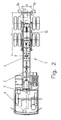
- FIGS 1 and 2 depict a vehicle, in this case a lorry 7, with a weighing arrangement according to the invention installed in it.
- the lorry 7 is equipped with a tipping platform 8, which is tipped about a pivot axle 12, transverse to the longitudinal direction of the vehicle, located in the rear of the lorry.
- This pivot axle 12 is fixedly attached to the lorry chassis and/or an auxiliary chassis 9.
- the tilting of the platform 8 is in this case by means of a hydraulic cylinder 6, which is at a considerable distance L from the pivot axle 12 in the longitudinal direction of the vehicle.
- the load-bearing parts of the platform rest on the auxiliary chassis 9, and the platform 8 front end, which is thus the opposite end of the platform in relation to the pivot axle 12, is supported by a centering structure 11.
- the pressure in the hydraulic cylinder 6 is raised, whereupon the cylinder length increases and the platform pivots about the pivot axle 12, whereupon, the platform being at a considerably large angle, often approx. 45°, it becomes emptied from the loaded material.
- the first and second sensor means 1a, 1b which are either similar or mirror images of each other, depending on the structure in each given case, are installed on the pivot axle 12 at a distance P, transverse to the lorry, from each other.
- This distance P is substantial as compared with the parallel width of the platform and the vehicle, and it is at least one-third of the vehicle width, usually approx. one-half - 2/3 of the vehicle width and at maximum approx. equal to the vehicle width.
- the third sensor means belonging to the measuring system is installed in conjunction with the lifting cylinder 6.
- the sensor is a pressure gauge 2, which is installed to measure the pressure of the fluid volume in connection with the lifting cylinder 6.
- the substantial distance in the longitudinal direction of the vehicle is L
- the effect of a longitudinal tilt of the vehicle can be corrected by using these two sensor groups 1a, b and respectively 6, 2, and the distribution of the load on the platform in the longitudinal direction can be detected.
- the measuring thus takes place at a minimum of three points, i.e. at points 1a, 1b, and 6, in which case, when necessary, it is possible to compute not only the total weight but also, on the basis of the longitudinal and transverse weight distributions, the axle weights or, for example, weights on each wheel or on each wheel set.
- the platform is raised by the hydraulic cylinder 6 just to the extent that the load-bearing structures 10 of the platform become separated from the auxiliary chassis 9 and the centering means 11 also become separated from each other, that none of the parts of the platform will bear during loading on the auxiliary chassis 9 of the vehicle or on its other chassis structures, but the platform 8 bears merely on points 1a and 1b and 6.
- the raising by the hydraulic cylinder 6 required for this is, however, so slight that it has no tipping effect.
- all of the sensor means are located and planned so that, at the points in question, the loading forces F1, F2, F3, F4, F5 in their totality are transferred via the sensor means to the vehicle chassis or auxiliary chassis 9. Also, for the duration of measuring, the fluid volume of the hydraulic cylinder is locked when the platform is in its said upward-tilted position, whereupon the platform 8 will bear rigidly and non-yieldingly on the said three sensor units, in which case no error sources due to yield are effective.
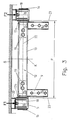
- FIGS 3 and 5 depict in greater detail the structure of the pivot axle.
- the pivot axle 12 is made up of a pipe 13, the ends of which are rigidly attached to the longitudinal beams 14 of the auxiliary chassis 9.
- the sensors 1a, b are attached to the ends of this pipe 13 so that the locking part 15 of the sensors will be inside the pipe 13 and be attached to it rigidly and non-rotatingly, for example by using through-going bolts 19 or in some other similar manner.
- the bearing part 16 of the sensors 1a, b projects from the ends 17a and respectively 17b of the pipe 13, in the manner of a cantilever beam.
- the pivot articulation 18 of the platform will be on this bearing part 16, forming a loop around it, as can be seen in Figure 5.
- the pivot articulation 18 is attached to the platform 8 by using platform-chassis fasteners 20.
- the outer surfaces of the bearing parts 16 of the sensors 1a, b having been shaped as circular cylinders and the holes 21 of the pivot articulations 18 attached to the platform having been shaped as corresponding cylindrical surfaces, pivot bearings 5 are formed on both sides of the center line of the platform when the pivot axles are installed on the bearing parts.
- the platform 8 is capable of turning about the axis 22, the bearing parts 16 of the sensors constituting the hinge pins.
- the important point is that, when the platform is being tilted, the pivot axle will not cause torsion, at least not considerable, in the sensors; the pivoting takes place with low resistance.
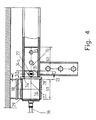
- FIGS 4 and 6 show details of this sensor structure, i.e. the bearing part 16 serving as the pin of the pivot bearing 5 of the sensor 1b, and around this part 16 the pivot articulation 18 turning about the axis 22 and the locking part 15.
- Each of the sensors 1a and lb is preferably formed from a continuous metal piece, in which there are made, for example by turning or machining in some other way, the said bearing part 16 and locking part 15.
- the surface pressure of the pivot articulation against the bearing part 16 ends at the interface 23.
- strain gauges 27a, 27b On both sides of this web 25 there are attached strain gauges 27a, 27b in the center of the recesses in relation to the horizontal symmetry axis 26 of the recesses 24a, b.
- the electric couplings of the strain gauges 27a, b are led from the sensor 1a, b along some suitable conduit, such as a wire 36, or alternatively in a non-depicted manner, via the locking part 15 to the computing unit 3 of the vehicle.
- the strain gauges may be of any commercially available type suitable for this purpose, and they are installed in the same manner as strain gauges of the type concerned are otherwise installed in an I-beam.
- a flange 28 which serves as a stop surface parallel to the axis 22 of the pivot articulation 18 and at the same time helps to insulate the placement point of the strain gauges.
- a clearance 34 Between the flange 28 and the end of the pipe 13 there is a small clearance 34 and, likewise, between the outer surface of the I-beam portion S3 and the inner surface of the pipe 13 there is a clearance 35, these clearances making it possible for the I-beam portion S3 to deflect.
- a load arriving on the platform induces a force F1 in the sensor 1b and respectively a force F2 in the sensor 1a, which forces thus often are not equal and produce in the sensors within the portion S3 deflections from which the shear stress component is measured by strain gauges 27a, b.
- the shear stress components are proportional to the force components F1, F2 in each given case, and they can be easily converted into displays, dependent on the weight, in the display device 4 in the vehicle.
- a preferred structural form of the sensor 1a, b has been described here, but it is clear that the invention is not limited specifically to this form; especially the locking part 15, specifically its cross sectional shape, may be of a different type, for example rectangular.
- the recesses 24, especially their cross sectional shape may be other than round, for example in the representation of Figure 4 rectangular, in which case their bottoms may be approximately flat or curved.
- the recesses may also be oblong with rounded ends or have some other shape.
- the sensors may be made from several parts which are coupled to each other in a suitable manner, but in general the best result is obtained by using a continuous material.
- the pivot articulation 18 may be installed on the bearing part 16 even otherwise than so as to surround it.
- the pivot articulation may be made up, for example only of a semicircular segment, or it may bear, by its projecting edge parallel to the axis 22, on a corresponding groove in the bearing part 16, or the pivot articulation may constitute, contrary to the embodiment depicted in the figures, the pin-like male part of the pivot bearing 5, the part bearing on the center of the cylindrical female part of the sensor and forming the pivot bearing.
- the essential point is that the loading force F1 and respectively F2 is transmitted directly to the predetermined first cantilever-like portion S1 of the length of the sensor 1a, b, and that the second portion S2 of the sensor length is rigidly attached to the vehicle chassis, the devices which convert the strains induced in this sensor piece under the effect of loading, such as strain gauges 27, being situated within the area between these portions S1 and S2, for example in the I-beam-like portion S3, and that at least two such sensor means have been installed at a substantial distance P from each other and symmetrically on both sides of the vertical plane K running through the center line of the vehicle.
- the third sensor means may thus be a pressure gauge arranged in conjunction with the fluid space of the lifting cylinder 6 and measuring the pressure of the fixed liquid volume during loading and being of any suitable commercially available pressure gauge type, which may be installed either directly at a suitable point of the cylinder 6 wall or to the pipes connected with it, as is the sensor 2 in Figure 2.
- This sensor 2 is connected to the computing unit 3, as are the sensors 1a, b, in order to give weighing results to the display 4.
- the sensor arranged in conjunction with the lifting cylinder 6 may also be implemented using strain gauges, for example in the manner depicted in Figures 7 and 8, in which the sensor 30 is made up of an at least approximately continuous metal piece 32, transverse to the vehicle, i.e. parallel to the axis 22, there being drilled in this metal piece, on both the front side and the back side and symmetrically in relation to the center line K of the vehicle, four recesses 31a-d, the lifting cylinder bearing centrally between them.
- the components F5 and F4 of the loading force are introduced to this deflection sensor 30, close to its ends outside the recesses 31a-d, whereupon the strain gauges 33 installed in the recesses will transmit a measuring signal proportional to the shear stress, as do sensors 1a, 1b. Some other design may also be applied to this sensor.
- the apparatus includes two lifting cylinders, it is possible to use a pressure gauge connected to their joint fluid space, or separate sensors for each cylinder, measuring the pressure of the liquid volume of each separately, or sensors based on strain gauges, for example, of the type depicted, in each.
Landscapes
- Physics & Mathematics (AREA)
- General Physics & Mathematics (AREA)
- Vehicle Body Suspensions (AREA)
- Measurement Of Force In General (AREA)
- Spinning Or Twisting Of Yarns (AREA)
- Supplying Of Containers To The Packaging Station (AREA)
- Force Measurement Appropriate To Specific Purposes (AREA)
- Measuring Pulse, Heart Rate, Blood Pressure Or Blood Flow (AREA)
- Escalators And Moving Walkways (AREA)
Applications Claiming Priority (2)
| Application Number | Priority Date | Filing Date | Title |
|---|---|---|---|
| FI895647A FI84103C (fi) | 1989-11-24 | 1989-11-24 | Arrangemang foer vaegning av en last. |
| FI895647 | 1989-11-24 |
Publications (2)
| Publication Number | Publication Date |
|---|---|
| EP0430393A1 true EP0430393A1 (de) | 1991-06-05 |
| EP0430393B1 EP0430393B1 (de) | 1995-11-29 |
Family
ID=8529419
Family Applications (1)
| Application Number | Title | Priority Date | Filing Date |
|---|---|---|---|
| EP90306977A Expired - Lifetime EP0430393B1 (de) | 1989-11-24 | 1990-06-26 | Anordnung zum Wägen einer Last |
Country Status (4)
| Country | Link |
|---|---|
| EP (1) | EP0430393B1 (de) |
| AT (1) | ATE130935T1 (de) |
| DE (1) | DE69023888T2 (de) |
| FI (1) | FI84103C (de) |
Cited By (2)
| Publication number | Priority date | Publication date | Assignee | Title |
|---|---|---|---|---|
| WO1995020142A1 (en) * | 1994-01-21 | 1995-07-27 | Adrian J. Paul Company | Decimal balance |
| US5789714A (en) * | 1996-02-28 | 1998-08-04 | Adrian J. Paul Co., Inc. | Method and apparatus for weighing a load |
Citations (4)
| Publication number | Priority date | Publication date | Assignee | Title |
|---|---|---|---|---|
| US3857452A (en) * | 1974-02-14 | 1974-12-31 | Tri Coastal Ind Inc | Dump truck load-sensing assembly |
| EP0054000A1 (de) * | 1980-12-09 | 1982-06-16 | Vibro-Meter Sa | Vorrichtung zur Messung der Nutzlast und des Achsenlast eines Lastwagens |
| EP0223384A1 (de) * | 1985-10-05 | 1987-05-27 | Manterfield, Kenneth Charles | Fahrzeuglastüberwachungssystem |
| US4694921A (en) * | 1986-10-20 | 1987-09-22 | Butler Manufacturing Company | Shear beam weigh axle transducer |
Family Cites Families (1)
| Publication number | Priority date | Publication date | Assignee | Title |
|---|---|---|---|---|
| US3376537A (en) * | 1966-02-11 | 1968-04-02 | Bytrex Inc | Shear strain load cell |
-
1989
- 1989-11-24 FI FI895647A patent/FI84103C/fi active IP Right Grant
-
1990
- 1990-06-26 EP EP90306977A patent/EP0430393B1/de not_active Expired - Lifetime
- 1990-06-26 DE DE69023888T patent/DE69023888T2/de not_active Expired - Fee Related
- 1990-06-26 AT AT90306977T patent/ATE130935T1/de not_active IP Right Cessation
Patent Citations (4)
| Publication number | Priority date | Publication date | Assignee | Title |
|---|---|---|---|---|
| US3857452A (en) * | 1974-02-14 | 1974-12-31 | Tri Coastal Ind Inc | Dump truck load-sensing assembly |
| EP0054000A1 (de) * | 1980-12-09 | 1982-06-16 | Vibro-Meter Sa | Vorrichtung zur Messung der Nutzlast und des Achsenlast eines Lastwagens |
| EP0223384A1 (de) * | 1985-10-05 | 1987-05-27 | Manterfield, Kenneth Charles | Fahrzeuglastüberwachungssystem |
| US4694921A (en) * | 1986-10-20 | 1987-09-22 | Butler Manufacturing Company | Shear beam weigh axle transducer |
Cited By (2)
| Publication number | Priority date | Publication date | Assignee | Title |
|---|---|---|---|---|
| WO1995020142A1 (en) * | 1994-01-21 | 1995-07-27 | Adrian J. Paul Company | Decimal balance |
| US5789714A (en) * | 1996-02-28 | 1998-08-04 | Adrian J. Paul Co., Inc. | Method and apparatus for weighing a load |
Also Published As
| Publication number | Publication date |
|---|---|
| FI84103C (fi) | 1991-10-10 |
| FI84103B (fi) | 1991-06-28 |
| FI895647A7 (fi) | 1991-05-25 |
| EP0430393B1 (de) | 1995-11-29 |
| ATE130935T1 (de) | 1995-12-15 |
| FI895647A0 (fi) | 1989-11-24 |
| DE69023888D1 (de) | 1996-01-11 |
| DE69023888T2 (de) | 1996-04-18 |
Similar Documents
| Publication | Publication Date | Title |
|---|---|---|
| CA1044713A (en) | Method of indicating a load placed on a load-carrying vehicle platform and corresponding apparatus | |
| US5067572A (en) | Dynamic payload monitor | |
| JP2659444B2 (ja) | 動的ペイロード・モニタ | |
| US5070953A (en) | Dynamic payload monitor | |
| US5182712A (en) | Dynamic payload monitor | |
| EP0496786B1 (de) | Verfahren und gerät zur nutzlastüberwachung | |
| US5917159A (en) | Dynamic load weighing system | |
| JPS6134425A (ja) | ダンプトラツクの積載重量測定方法 | |
| US3960228A (en) | Shear beam load cell | |
| CA1266869A (en) | Vehicle load monitoring system | |
| US4037469A (en) | Force measuring apparatus | |
| US4828055A (en) | Weighbridge with pivotal supporting system | |
| GB2037444A (en) | Force measuring dynamometric device for a load handling machine | |
| EP0430393B1 (de) | Anordnung zum Wägen einer Last | |
| GB2487608A (en) | Clevis pin strain sensor for vehicle payload weighing | |
| JP4028609B2 (ja) | 傾斜荷台付き車両の積載物の重量測定装置 | |
| US8436261B2 (en) | Cantilever beam scale | |
| CA1044261A (en) | Vehicle load measuring system | |
| WO1994003784A1 (en) | Compensated load measuring device | |
| JP3913665B2 (ja) | 計量器の検量方法 | |
| FI88437B (fi) | Arrangemang foer vaegning av en last | |
| AU696605B2 (en) | Compensated load measuring device | |
| WO1998012516A1 (en) | Dynamic load weighing system | |
| AU4689993A (en) | Compensated load measuring device |
Legal Events
| Date | Code | Title | Description |
|---|---|---|---|
| PUAI | Public reference made under article 153(3) epc to a published international application that has entered the european phase |
Free format text: ORIGINAL CODE: 0009012 |
|
| AK | Designated contracting states |
Kind code of ref document: A1 Designated state(s): AT BE CH DE DK ES FR GB GR IT LI LU NL SE |
|
| 17P | Request for examination filed |
Effective date: 19911129 |
|
| 17Q | First examination report despatched |
Effective date: 19920814 |
|
| GRAA | (expected) grant |
Free format text: ORIGINAL CODE: 0009210 |
|
| AK | Designated contracting states |
Kind code of ref document: B1 Designated state(s): AT BE CH DE DK ES FR GB GR IT LI LU NL SE |
|
| PG25 | Lapsed in a contracting state [announced via postgrant information from national office to epo] |
Ref country code: IT Free format text: LAPSE BECAUSE OF FAILURE TO SUBMIT A TRANSLATION OF THE DESCRIPTION OR TO PAY THE FEE WITHIN THE PRE;WARNING: LAPSES OF ITALIAN PATENTS WITH EFFECTIVE DATE BEFORE 2007 MAY HAVE OCCURRED AT ANY TIME BEFORE 2007. THE CORRECT EFFECTIVE DATE MAY BE DIFFERENT FROM THE ONE RECORDED.SCRIBED TIME-LIMIT Effective date: 19951129 Ref country code: NL Free format text: LAPSE BECAUSE OF FAILURE TO SUBMIT A TRANSLATION OF THE DESCRIPTION OR TO PAY THE FEE WITHIN THE PRESCRIBED TIME-LIMIT Effective date: 19951129 Ref country code: BE Effective date: 19951129 Ref country code: ES Free format text: THE PATENT HAS BEEN ANNULLED BY A DECISION OF A NATIONAL AUTHORITY Effective date: 19951129 Ref country code: DK Effective date: 19951129 Ref country code: GR Free format text: LAPSE BECAUSE OF FAILURE TO SUBMIT A TRANSLATION OF THE DESCRIPTION OR TO PAY THE FEE WITHIN THE PRESCRIBED TIME-LIMIT Effective date: 19951129 Ref country code: FR Effective date: 19951129 |
|
| REF | Corresponds to: |
Ref document number: 130935 Country of ref document: AT Date of ref document: 19951215 Kind code of ref document: T |
|
| REF | Corresponds to: |
Ref document number: 69023888 Country of ref document: DE Date of ref document: 19960111 |
|
| REG | Reference to a national code |
Ref country code: CH Ref legal event code: NV Representative=s name: SCHAAD, BALASS & PARTNER AG |
|
| PG25 | Lapsed in a contracting state [announced via postgrant information from national office to epo] |
Ref country code: SE Effective date: 19960229 |
|
| EN | Fr: translation not filed | ||
| NLV1 | Nl: lapsed or annulled due to failure to fulfill the requirements of art. 29p and 29m of the patents act | ||
| PG25 | Lapsed in a contracting state [announced via postgrant information from national office to epo] |
Ref country code: GB Effective date: 19960626 |
|
| PG25 | Lapsed in a contracting state [announced via postgrant information from national office to epo] |
Ref country code: LU Free format text: LAPSE BECAUSE OF NON-PAYMENT OF DUE FEES Effective date: 19960630 |
|
| PLBE | No opposition filed within time limit |
Free format text: ORIGINAL CODE: 0009261 |
|
| STAA | Information on the status of an ep patent application or granted ep patent |
Free format text: STATUS: NO OPPOSITION FILED WITHIN TIME LIMIT |
|
| 26N | No opposition filed | ||
| GBPC | Gb: european patent ceased through non-payment of renewal fee |
Effective date: 19960626 |
|
| PGFP | Annual fee paid to national office [announced via postgrant information from national office to epo] |
Ref country code: DE Payment date: 20000620 Year of fee payment: 11 |
|
| PG25 | Lapsed in a contracting state [announced via postgrant information from national office to epo] |
Ref country code: DE Free format text: LAPSE BECAUSE OF NON-PAYMENT OF DUE FEES Effective date: 20020501 |
|
| APAH | Appeal reference modified |
Free format text: ORIGINAL CODE: EPIDOSCREFNO |
|
| PGFP | Annual fee paid to national office [announced via postgrant information from national office to epo] |
Ref country code: CH Payment date: 20080617 Year of fee payment: 19 |
|
| PGFP | Annual fee paid to national office [announced via postgrant information from national office to epo] |
Ref country code: AT Payment date: 20080625 Year of fee payment: 19 |
|
| REG | Reference to a national code |
Ref country code: CH Ref legal event code: PL |
|
| PG25 | Lapsed in a contracting state [announced via postgrant information from national office to epo] |
Ref country code: LI Free format text: LAPSE BECAUSE OF NON-PAYMENT OF DUE FEES Effective date: 20090630 Ref country code: CH Free format text: LAPSE BECAUSE OF NON-PAYMENT OF DUE FEES Effective date: 20090630 |
|
| PG25 | Lapsed in a contracting state [announced via postgrant information from national office to epo] |
Ref country code: AT Free format text: LAPSE BECAUSE OF NON-PAYMENT OF DUE FEES Effective date: 20090626 |