EP0430413B1 - Estimation de symboles de données - Google Patents
Estimation de symboles de données Download PDFInfo
- Publication number
- EP0430413B1 EP0430413B1 EP19900311158 EP90311158A EP0430413B1 EP 0430413 B1 EP0430413 B1 EP 0430413B1 EP 19900311158 EP19900311158 EP 19900311158 EP 90311158 A EP90311158 A EP 90311158A EP 0430413 B1 EP0430413 B1 EP 0430413B1
- Authority
- EP
- European Patent Office
- Prior art keywords
- partial path
- symbol
- symbol type
- state
- path metric
- Prior art date
- Legal status (The legal status is an assumption and is not a legal conclusion. Google has not performed a legal analysis and makes no representation as to the accuracy of the status listed.)
- Expired - Lifetime
Links
- 230000007704 transition Effects 0.000 claims description 26
- 238000000034 method Methods 0.000 claims description 25
- 230000005540 biological transmission Effects 0.000 claims description 22
- 238000004891 communication Methods 0.000 claims description 7
- 238000013139 quantization Methods 0.000 claims description 3
- 238000007476 Maximum Likelihood Methods 0.000 description 12
- 238000010586 diagram Methods 0.000 description 11
- 238000012545 processing Methods 0.000 description 7
- 230000008901 benefit Effects 0.000 description 3
- 238000012937 correction Methods 0.000 description 3
- 238000013459 approach Methods 0.000 description 2
- 238000001514 detection method Methods 0.000 description 2
- 102100036464 Activated RNA polymerase II transcriptional coactivator p15 Human genes 0.000 description 1
- 101100191136 Arabidopsis thaliana PCMP-A2 gene Proteins 0.000 description 1
- 101710130550 Class E basic helix-loop-helix protein 40 Proteins 0.000 description 1
- 102100025314 Deleted in esophageal cancer 1 Human genes 0.000 description 1
- 101000713904 Homo sapiens Activated RNA polymerase II transcriptional coactivator p15 Proteins 0.000 description 1
- 229910004444 SUB1 Inorganic materials 0.000 description 1
- 101100048260 Saccharomyces cerevisiae (strain ATCC 204508 / S288c) UBX2 gene Proteins 0.000 description 1
- 238000007796 conventional method Methods 0.000 description 1
- 230000003247 decreasing effect Effects 0.000 description 1
- 230000001627 detrimental effect Effects 0.000 description 1
- 230000000694 effects Effects 0.000 description 1
- 238000013507 mapping Methods 0.000 description 1
- 238000012986 modification Methods 0.000 description 1
- 230000004048 modification Effects 0.000 description 1
- 238000010606 normalization Methods 0.000 description 1
- 238000005070 sampling Methods 0.000 description 1
- 230000002123 temporal effect Effects 0.000 description 1
Images

Classifications
-
- H—ELECTRICITY
- H04—ELECTRIC COMMUNICATION TECHNIQUE
- H04L—TRANSMISSION OF DIGITAL INFORMATION, e.g. TELEGRAPHIC COMMUNICATION
- H04L25/00—Baseband systems
- H04L25/02—Details ; arrangements for supplying electrical power along data transmission lines
- H04L25/03—Shaping networks in transmitter or receiver, e.g. adaptive shaping networks
- H04L25/03006—Arrangements for removing intersymbol interference
- H04L25/03178—Arrangements involving sequence estimation techniques
- H04L25/03312—Arrangements specific to the provision of output signals
- H04L25/03318—Provision of soft decisions
Definitions
- This invention relates to a method and apparatus for estimating a data symbol in a sequence of transmitted data symbols received over a communication channel and has particular, but not exclusive application, in the equalization of data transmitted over radio channels.
- digitised signals are referred to as data.
- Viterbi equalizers based on the Viterbi algorithm, which are a form of maximum likelihood (ML) detector.
- data may be convolutionally encoded before it is transmitted.
- Forward error correction means that the data is corrected at the receiver without the need for retransmission).
- a Viterbi detector may also be used for decoding convolutionally encoded data.
- 'node' is usually used to designate a particular state at a particular time on a trellis diagram.
- the arc or path representing the transition between two states (nodes) adjacent in time is known as a 'branch' and the associated 'branch metric' is an indication of the likelihood of the particular transition occurring.
- the 'partial path metric' represents the overall probability that a particular partial path to the left of the node under consideration represents the correct sequence of state transitions.
- the term 'partial path' is construed accordingly. This is the meaning of the terms partial path and partial path metric as they are used in the present specification, but the terms 'path' and 'path metric' may also be used to convey the same meaning.
- the overall path i.e. the path between the beginning and the end of the trellis which has the maximum path metric is the maximum likelihood path which essentially represents the best estimate of the data symbols actually transmitted.
- the path metric is a numerical value indicating the relative likelihood (probability) of a particular transition taking place.
- the maximum path metric represents the maximum likelihood, but depending on the manner in which the path metric is determined the converse may equally hold true, namely that the maximum likelihood may be represented by a minimum path metric. Therefore the term 'maximum' as used in this specification must be understood to include 'minimum' and likewise the words 'larger' and 'smaller' (and like terms) must be understood to include their converse meanings, viz 'smaller' and 'larger' respectively.
- a maximum likelihood (ML) or maximum a-posteriori (MAP) detector may be used to calculate the branch metrics for every branch in the trellis diagram and then determine the path metric for every path in the trellis diagram, and finally choose the path for which the overall path metric is a maximum.
- the sequence of symbols corresponding to this path is the estimate of the symbols actually transmitted.
- the difficulty with this approach is that the number of paths increases exponentially as the trellis diagram is traversed from left to right.
- the Viterbi detector (mentioned earlier) is a computationally more efficient version of a ML detector which exploits the special structure of the detector to achieve a complexity that grows linearly rather than exponentially along the trellis.
- a Viterbi detector has the advantage that it requires a constant computation rate per unit time. For each node, the Viterbi detector selects the path having the largest partial path metric, called the 'survivor path' for that node. All partial paths other than the survivor path are discarded because any other partial path has by definition a smaller partial path metric, and hence if it replaced the survivor path in any overall path, the path metric would be smaller.
- the optimal path must pass through and so it is necessary to retain one survivor path for each and every node.
- the symbol associated with the survivor path, called the 'survivor', and the associated path metric have to be stored in memory for each node at a stage representing a particular time in order for the algorithm to proceed to the next stage at time increment t+1.
- the decisions made by a conventional Viterbi detector are 'hard' decisions in the sense that the estimated data symbols are restricted to correspond exactly to the data symbols of the particular alphabet used. For example, in the case of a 2-symbol alphabet the estimated data symbols are in strict binary digitized form (i.e. expressed in terms of only two levels, e.g. 0 and 1).
- the known Viterbi detector has the drawback that an appreciable time delay occurs between detection and output.
- the total time delay may typically amount to, say 70 bits which, by way of example, at a bit transmission rate of 270kb/s would correspond to a significant time delay of 0.26ms. This time lag is undesirable in data receivers generally, but is especially detrimental in the case of voice communication applications.
- Viterbi detector requires substantial memory capacity to store the survivor information.
- European patent application EP-A-0,302,330 relates to a method of evaluating metrics for Viterbi decoding of convoluted code signals in which individual path decisions are made for each state by comparing the pair of 'opposing' path metrics, i.e. the path metrics associated respectively with two different symbol types [designated M A (x,k+1) and M B (x,k+1) in the present application].
- the first path metric [M A (x,k+1)] of the opposing pair is calculated by adding the current branch metric [b(x,k+1
- the two opposing path metrics are differenced [M A (x,k+1)-M B (x,k+1)] to yield a path decision for each state.
- sixteen path decisions (denoted DEC0, DEC1,...DEC15 in EP-A-0,302,330) will be made.
- these path decisions are all stored in memory for selection and read back at a subsequent trace-back stage in the conventional manner of a Viterbi decoder.
- the two opposing path metrics are compared and the minimum value (MSEL0, MSEL1,...MSEL15) is selected for use as the previous partial path metric at the next transition stage of the trellis.
- a further stage (M-AND and PRE-MI) is provided for comparing all the minimum metrics (MSEL0, MSEL1,...MSEL15) and selecting the overall minimum value (MMIN) which is subtracted as an offset from each of the minimum metric values (MSEL0, MSEL1,...MSEL15) at each of the sixteen individual stages (viz. at subtractors SUB0, SUB1,...SUB15) in a process which may effectively be regarded as normalization. Additionally, the maximum of all the sixteen minimum metric values may be determined.
- the maximum and minimum values of the complete set of minimum metrics may be differenced to provide a so-called differential metric which (as mentioned in passing in EP-A-0,302,330) may be used, for example, for synchronization or for phase ambiguity resolution during Viterbi decoding.
- the preamble of claim 1 is based on EP-A-0,302,330.
- a method of estimating a data symbol in a sequence of transmitted data symbols received on a communication channel, wherein a plurality of different states is associated with the transmission of said data symbols which method includes the steps of determining for each state the respective partial path metric (M A ) in respect of the state transition corresponding to the transmission of a first symbol type (A), and determining for each state the respective partial path metric (M B ) in respect of the state transition corresponding to the transmission of a second symbol type (B), characterized by selecting the maximum value (M Amax and M Bmax ) of the first and second symbol type partial path metrics respectively, and determining the difference (M Amax -M Bmax or M Bmax -M Amax ) between the respective maximum values of the first and second symbol type partial path metrics (M Amax and M Bmax ).
- the difference between the respective maximum values of the first and second symbol type partial path metrics may be used directly as an estimate or "decision" of the transmitted data symbol.
- An important advantage of a method in accordance with the present invention is that the decisions are made almost instantaneously and continuously, e.g. at the same rate as the symbol sampling rate which may be chosen to be the same as the symbol transmission rate.
- this method avoids delay associated with survivor storage and also the trace-back phase which are inherent features of the known Viterbi detector.
- the present method avoids the need for storing survivor information no memory is required for this purpose.
- the processing circuitry can therefore be less complex, and hence less costly in this regard.
- the difference between the respective maximum values of the first and second symbol type partial path metrics may be used directly as a value indicative of the confidence level of an estimated data symbol.
- a method in accordance with the invention has the benefit that it can yield soft decisions. That is to say, the estimated data symbols may be quantized at more levels than there are symbols in the alphabet being used (for example at eight levels in the case of a 2-symbol (binary) alphabet) and thus inherently convey certainty information as regards the confidence level of the decision made.
- convolutionally encoded data when soft decisions are decoded a significantly better error rate performance can be achieved for a given signal to noise ratio, as compared to the hard decisions generated by the conventional Viterbi decoder.
- the respective selection steps include comparing the partial path metric for each state in turn with a previously selected value to determine and select the larger of the two values.
- an arrangement for estimating a data symbol in a sequence of transmitted data symbols received on a communication channel wherein a plurality of different states is associated with the transmission of said data symbols, including first means for determining for each state the respective partial path metric (M A ) in respect of the state transition corresponding to the transmission of a first symbol type (A), and second means for determining for each state the respective partial path metric (M B ) in respect of the state transition corresponding to the transmission of a second symbol type (B), characterized by means for selecting the maximum value (M Amax and M Bmax ) of the first and second symbol type partial path metrics respectively, and means for outputting a signal indicative of the difference (M Amax -M Bmax or M Bmax -M Amax ) between the maximum value of the first symbol type partial path metric (M Amax ) and the maximum value of the second symbol type partial path metric (M Bmax ).
- an arrangement in accordance with the present invention includes means for comparing the first symbol type partial path metric for each state with a previously selected value to determine and select the larger of the two values and means for comparing the second symbol type partial path metric for each state with a previously selected value to determine and select the larger of the two values.
- respective multiplexer means may be provided for applying the partial path metric for each state in turn to the respective comparing means.
- the arrangement additionally comprises means for quantising the signal from the outputting means into a plurality of quantization levels greater than the number of symbols in the data alphabet.
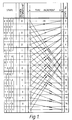
- Figure 1 is a part of a trellis diagram for the 16 states associated with a 2-symbol alphabet in the case where the constraint length is 4.
- the two symbols may, for example, be +1 and -1 mapped from the single bits 1 and 0 respectively.
- the states (0000, 0001 ....1110, 1111) are shown in the left hand (first) column and the decision estimated bit (i.e. the least significant bit) is shown in the column to the right of its respective state.
- the partial trellis diagram itself shows the state transitions for all 16 states at a time k and an incremented time k+1. The time interval between k and k+1 corresponds to the time interval between successive transmitted data symbols.
- Transitions with a single arrowhead represent a, 0 transition bit, whereas transitions with a double arrowhead represent a 1 transition bit.
- a state transition occurs as a result, of adding the transition bit to the current state in the position of the most significant bit and disregarding the least significant bit (i.e. the decision estimated bit) of the current state.
- the number of the state (0-15) is shown to the right of the trellis diagram.
- the partial path metric for any particular state 0 to 15 at time k+1 is given by the sum of the partial path metric at time k plus the branch metric between k and k+1.
- M(x k+1 ,k + 1) M(x k ,k) + b(x k+1 ,k+1
- M is the partial path metric
- b is the branch metric
- x k is the state number
- k is the time index.
- M(x,k+1) is the partial path metric at state number x k+1 at time k+1
- M(x,k) is the partial path metric at state number x k+1 at time k
- x,k) is the branch metric at state number x k at time k + 1 given the state number x k at time k.
- the branch metrics can be determined using conventional techniques which will be familiar to a person skilled in the art.
- a novel multiplier-less approach may be used in accordance with the invention which is the subject of our co-pending European patent publication No.EP-430428 claiming priority from UK patent application No. 8927006.0.
- the two partial path metrics corresponding to a transmitted A and B symbol are:
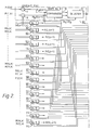
- the arrangement in Figure 2 shows how the partial path metric information is processed to derive an almost immediate estimate of the current data symbol at time k+1.
- the processing blocks 101-115 for states 1 to 15 respectively are all functionally equivalent to the processing block 100 for state 0, shown bounded by a chain line in Figure 2.
- the multiplexer transmits each of the partial path metric input values as a first input y to a comparator 3.
- the second input x to the comparator may initially be set at 0.
- the comparator indicates which is the larger of the two values x and y and the subsequent selector stage 4 selects the larger of the two values and feeds it back to the input x of comparator 3.
- the input x thus remains constant unless the input at y is greater in which case the input x assumes the higher value.
- the selector outputs the maximum value of the partial path metric for the symbol A over all sixteen states. This value is represented as M Amax .
- comparator 6 and selector 7 are used to determine the maximum value of the partial path metrics for the B symbol over all sixteen states.
- the multiplexer 5 has sixteen inputs, viz. M B (0,k+1).
- M B (0,k+1).
- M B (15,k+1) being the values of the partial path metrics at each of the sixteen states respectively and corresponding to the transmission of a data symbol B.
- the drawing shows how the value M B (0,k+1) is determined at adder 8 by summing the value of the partial path metric M(1,k) and the value of the branch metric b(0,k+1
- the equivalent process is carried out at each of the fifteen remaining states to determine the respective partial path metric for the B symbol.
- the comparator 6 and selector 7 are effective to output the maximum value of the partial path metric for the symbol B over all sixteen states. This value is represented as M Bmax .
- the value M Amax from selector 4 is fed to an adder 9.
- the value M Bmax is inverted (made negative) and also fed to the adder 9 which thus combines the two input values to give the difference M Amax - M Bmax .
- the Applicants have used a quantiser 12 to quantise the estimated data symbols into eight levels.
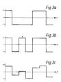
- the output from the quantiser 12 in this case is a sequence of three bits where 000 represents a first transmitted data symbol of the binary pair (i.e. A or -1) with maximum certainty, 001 represents the same data symbol with less certainty, 010 represents the same data symbol with even less certainty and 011 represents the same data symbol with minimum certainty.
- 111 represents the other symbol of the binary pair (hence B or + 1) and 110, 101, and 100 represent the same symbol with gradually decreasing certainty.
- the output from the adder 9 may already be quantized at the desired number of levels, in which case the quantiser 12 can be dispensed with.
- a further comparator 10 and selector 11 are provided within the respective processing blocks 100-115.
- Each comparator compares the two respective inputs at a given time, say k+1, corresponding to the partial path metrics corresponding to the transmission of an A and B symbol respectively.
- the output M A (0,k+1) from adder 1 and the output M B (0,k+1) from adder 8 are applied to the comparator 10 and selector 11 which gives an output M(0,k+1) corresponding to the maximum value of this pair of partial path metrics.
- This information is used to estimate the transmitted data signal at the next successive increment k+2 when, in order to proceed along the trellis, it is necessary to know the partial path metric for each state at time k+1. Thus this same comparison and selection process is carried out in parallel for each of the sixteen states at each time increment.
- the full sequence of estimated data symbols may be further processed by a decoder.
- the decoder may suitably be a conventional Viterbi decoder since only hard decisions are required at the decoder output.
- a decoder in accordance with the present invention may be employed, wherein only the hard decision component of the soft decision is utilized. The availability of soft decisions at the decoder input enables the overall bit error performance to be improved compared with hard decisions, since the decoder is able to utilize the certainty information in arriving at a final more accurate decision.
- the decoder is used for recovering the original data from data which has been convolutionally encoded before transmission.
- the plus or minus sign between terms is determined by the particular mapping scheme used.
- a 1 maps to a plus sign (+) and a 0 maps to a minus sign (-).
- Figure 3 shows a typical sequence of soft decisions (estimated in accordance with the invention (see Figure 3c), in contrast to the equivalent hard decisions which may have been made by a prior art Viterbi detector (see Figure 3b), compared with the original encoded data symbols which were actually transmitted (see Figure 3a). It can be seen that in the case of the hard decisions a wrong decision was made for the symbol at X. By contrast, in the soft decision case this is estimated as a probable +1 symbol but with minimal certainty. At the decoder stage this uncertainty will be taken into account and may result in the effect of this particular decision with a high level of uncertainty being reversed, i.e. corrected. This is the reason why a receiver incorporating an equalizer in accordance with the invention has the potential to significantly improve the error rate performance for a given signal to noise ratio.
- the decisions obtained using a method in accordance with the present invention may be combined with respective hard decision information derived separately using conventional Viterbi techniques.
- the hard decision may be used to represent the sign of the decision estimated bit (where a plus sign is mapped to 1 and a minus sign is mapped to 0) while the decision obtained using the present method is used to indicate the confidence level of the hard decision.
Landscapes
- Engineering & Computer Science (AREA)
- Power Engineering (AREA)
- Computer Networks & Wireless Communication (AREA)
- Signal Processing (AREA)
- Error Detection And Correction (AREA)
Claims (11)
- Procédé pour estimer un symbole de donnée dans une séquence de symboles de données transmis qui sont reçus sur un canal de communication, dans lequel une multitude d'états différents est associée à la transmission desdits symboles de données, procédé qui comprend les étapes consistant à :- déterminer pour chaque état la métrique du trajet partiel respectif (MA ) eu égard à la transition d'état correspondant à la transmission d'un premier type de symbole (A), et- déterminer pour chaque état la métrique du trajet partiel respectif (MB) eu égard à la transition d'état correspondant à la transmission d'un second type de symbole (B),caractérisé par les étapes consistant à sélectionner la valeur maximum (MAmax et MBmax) des métriques des trajets partiels des premier et second types de symboles, respectivement, et
- déterminer la différence (MAmax-MBmax ou MBmax-MAmax) entre les valeurs maximales respectives des métriques des trajets partiels des premier et second types de symboles (MAmax et MBmax). - Procédé selon la revendication 1, comprenant l'utilisation de la différence entre les valeurs maximales respectives des métriques des trajets partiels des premier et second types de symboles comme une estimation représentative du symbole de donnée transmis.
- Procédé selon la revendication 1, comprenant l'utilisation de la différence entre les valeurs maximales respectives des métriques des trajets partiels des premier et second types de symboles comme une valeur représentative du niveau de confiance d'un symbole de donnée estimé.
- Procédé selon la revendication 1, comprenant l'utilisation de la différence entre les valeurs maximales respectives des métriques des trajets partiels des premier et second types de symboles à la fois comme une estimation représentative du symbole de donnée transmis et aussi comme une valeur représentative du niveau de confiance de ladite estimation.
- Procédé selon la revendication 3 ou 4, dans lequel la différence entre les valeurs maximales respectives des métriques des trajets partiels des premier et second types de symboles est sortie à l'une d'une multitude de niveaux de quantification supérieurs au nombre des symboles dans l'alphabet des données.
- Procédé selon l'une quelconque des revendications précédentes, dans lequel les étapes de sélection respectives comprennent l'étape de comparaison des métriques des trajets partiels pour chaque état, tour à tour, avec une valeur précédemment sélectionnée pour déterminer et choisir la plus grande des deux valeurs.
- Agencement pour estimer un symbole de donnée dans une séquence de symboles de données transmis qui sont reçus sur un canal de communication, dans lequel une multitude d'états différents est associée à la transmission desdits symboles de données, comprenant:- un premier moyen (1) pour déterminer pour chaque état la métrique respective du trajet partiel (MA) eu égard à la transition d'état correspondant à la transmission d'un premier type de symbole (A), et- un second moyen (2) pour déterminer pour chaque état la métrique respective du trajet partiel (MB) eu égard à la transition d'état correspondant à la transmission d'un second type de symbole (B), caractérisé par :- un moyen (2, 3, 4) pour sélectionner la valeur maximum (MAmax et MBmax) des métriques des trajets partiels des premier et second types de symboles, respectivement, et- un moyen (9) pour sortir un signal représentatif de la différence (MAmax-MBmax ou MBmax-MAmax) entre la valeurs maximum de la métrique du trajet partiel du premier type de symbole (MAmax) et la valeur maximum de la métrique du trajet partiel du second type de symbole (MBmax).
- Agencement selon la revendication 7, comprenant un moyen (3, 4) pour comparer la métrique du trajet partiel du premier type de symbole pour chaque état à une valeur précédemment sélectionnée pour déterminer et choisir la plus grande des deux valeurs et un moyen (5, 6) pour comparer la métrique du trajet partiel du second type de symbole pour chaque état à une valeur précédemment sélectionnée pour déterminer et choisir la plus grande des deux valeurs.
- Agencement selon la revendication 8, comprenant un moyen de multiplexeur respectif (2; 5) pour appliquer la métrique du trajet partiel pour chaque état, tour à tour, au moyen de comparaison respectif (3, 4; 6, 7).
- Agencement selon l'une quelconque des revendications 7 à 9, comprenant en outre un moyen pour quantifier le signal provenant du moyen de sortie (9) en une multitude de niveaux de quantification supérieurs au nombre des symboles dans l'alphabet des données.
- Appareil de réception de données comprenant (i) un égaliseur comportant un agencement afin d'estimer un symbole de donnée tel que revendiqué dans l'une des revendications 7 à 10, et (ii) un moyen de décodage afin de décoder les signaux émis par le moyen de sortie (9), ledit moyen de décodage comprenant aussi un agencement pour estimer un symbole de donnée tel que revendiqué dans l'une quelconque des revendications 7 à 10.
Applications Claiming Priority (2)
| Application Number | Priority Date | Filing Date | Title |
|---|---|---|---|
| GB8927005A GB2238692B (en) | 1989-11-29 | 1989-11-29 | Data symbol estimation |
| GB8927005 | 1989-11-29 |
Publications (3)
| Publication Number | Publication Date |
|---|---|
| EP0430413A2 EP0430413A2 (fr) | 1991-06-05 |
| EP0430413A3 EP0430413A3 (en) | 1991-07-17 |
| EP0430413B1 true EP0430413B1 (fr) | 1994-09-14 |
Family
ID=10667134
Family Applications (1)
| Application Number | Title | Priority Date | Filing Date |
|---|---|---|---|
| EP19900311158 Expired - Lifetime EP0430413B1 (fr) | 1989-11-29 | 1990-10-11 | Estimation de symboles de données |
Country Status (3)
| Country | Link |
|---|---|
| EP (1) | EP0430413B1 (fr) |
| DE (1) | DE69012518T2 (fr) |
| GB (1) | GB2238692B (fr) |
Cited By (2)
| Publication number | Priority date | Publication date | Assignee | Title |
|---|---|---|---|---|
| DE19509867A1 (de) * | 1995-03-17 | 1996-09-26 | Siemens Ag | Übertragungsverfahren zum gleichzeitigen synchronen oder asynchronen Übertragen von K aus Datensymbolen bestehenden Datenfolgen |
| AU728649B2 (en) * | 1996-08-09 | 2001-01-11 | Nokia Telecommunications Oy | Method for determining connection quality, and a receiver |
Families Citing this family (3)
| Publication number | Priority date | Publication date | Assignee | Title |
|---|---|---|---|---|
| GB2281179B (en) * | 1993-08-18 | 1998-03-11 | Roke Manor Research | Apparatus for use in equipment providing a digital radio link between a fixed and a mobile radio unit |
| DE69429161T2 (de) | 1993-11-29 | 2002-06-20 | Oki Electric Industry Co., Ltd. | Gerät zur schätzung analog entschiedener werte und eines höchstwahrscheinlichkeitssystems |
| US5717723A (en) * | 1994-08-17 | 1998-02-10 | Roke Manor Research Limited | Apparatus for use in equipment providing a digital radio link between a fixed radio unit and a mobile radio unit |
Family Cites Families (1)
| Publication number | Priority date | Publication date | Assignee | Title |
|---|---|---|---|---|
| DE3725655A1 (de) * | 1987-08-03 | 1989-02-16 | Ant Nachrichtentech | Verfahren zum auswerten von zweig- und pfadmetriken sowie anordnung |
-
1989
- 1989-11-29 GB GB8927005A patent/GB2238692B/en not_active Expired - Fee Related
-
1990
- 1990-10-11 DE DE1990612518 patent/DE69012518T2/de not_active Expired - Lifetime
- 1990-10-11 EP EP19900311158 patent/EP0430413B1/fr not_active Expired - Lifetime
Cited By (4)
| Publication number | Priority date | Publication date | Assignee | Title |
|---|---|---|---|---|
| DE19509867A1 (de) * | 1995-03-17 | 1996-09-26 | Siemens Ag | Übertragungsverfahren zum gleichzeitigen synchronen oder asynchronen Übertragen von K aus Datensymbolen bestehenden Datenfolgen |
| US5793814A (en) * | 1995-03-17 | 1998-08-11 | Siemens Aktiengesellschaft | Transmission method for simultaneous synchronous or asynchronous transmission of K data sequences consisting of data symbols |
| AU728649B2 (en) * | 1996-08-09 | 2001-01-11 | Nokia Telecommunications Oy | Method for determining connection quality, and a receiver |
| US6748035B2 (en) | 1996-08-09 | 2004-06-08 | Nokia Corporation | Method for determining connection quality, and a receiver |
Also Published As
| Publication number | Publication date |
|---|---|
| GB2238692B (en) | 1993-12-01 |
| DE69012518T2 (de) | 1995-04-20 |
| GB8927005D0 (en) | 1990-01-17 |
| GB2238692A (en) | 1991-06-05 |
| DE69012518D1 (de) | 1994-10-20 |
| EP0430413A3 (en) | 1991-07-17 |
| EP0430413A2 (fr) | 1991-06-05 |
Similar Documents
| Publication | Publication Date | Title |
|---|---|---|
| US5185747A (en) | Data symbol estimation | |
| US5502735A (en) | Maximum likelihood sequence detector | |
| US5844946A (en) | Soft-decision receiver and decoder for digital communication | |
| US5119400A (en) | Digital transmission system employing a viterbi-like equalizer | |
| US6148431A (en) | Add compare select circuit and method implementing a viterbi algorithm | |
| EP0771080B1 (fr) | Décodage à maximum de vraisemblance avec décisions douces | |
| US5375129A (en) | Maximum likelihood sequence detector | |
| EP0670636A1 (fr) | Processeur Viterbi | |
| KR100554322B1 (ko) | 복수의 코딩 버스트내에 배치된 crc 비트에 의해 종료 상태가결정되는 컨벌루셔널 디코딩 | |
| US5511081A (en) | Method for source-controlled channel decoding by expanding the Viterbi algorithm | |
| EP1236282A1 (fr) | Algorithme d'estimation de symbole a recherche limitee | |
| KR100210534B1 (ko) | 디지탈 전송 시스템용 수신기 | |
| EP0800280A1 (fr) | Décodage Viterbi à décisions douces avec information de vraisemblance basée sur une différence de métriques de chemin | |
| US5822340A (en) | Method for decoding data signals using fixed-length decision window | |
| EP0430413B1 (fr) | Estimation de symboles de données | |
| EP0467522B1 (fr) | Détecteur de séquence à maximum de vraisemblance | |
| US6782060B2 (en) | Method and apparatus for generating reliability information for channel decoding in a radio receiver | |
| MXPA00008251A (es) | Decodificador de convolucion parcialmente paralelo aparato y metodo. | |
| JP4024364B2 (ja) | デジタル伝送システム、デジタル信号の受信機及びデジタル信号の受信方法 | |
| WO2002071710A1 (fr) | Procede d'amelioration d'informations temporaires | |
| GB2238693A (en) | Data symbol estimation | |
| US5751734A (en) | Decoding method and apparatus using trace deletion for Viterbi algorithm | |
| JP2591332B2 (ja) | 誤り訂正復号装置 | |
| JPH11500298A (ja) | 遷移距離を形成する方法及びセルラー無線システムの受信器 | |
| JP2551027B2 (ja) | 逐次復号方法及び装置 |
Legal Events
| Date | Code | Title | Description |
|---|---|---|---|
| PUAI | Public reference made under article 153(3) epc to a published international application that has entered the european phase |
Free format text: ORIGINAL CODE: 0009012 |
|
| PUAL | Search report despatched |
Free format text: ORIGINAL CODE: 0009013 |
|
| AK | Designated contracting states |
Kind code of ref document: A2 Designated state(s): DE FR GB IT SE |
|
| AK | Designated contracting states |
Kind code of ref document: A3 Designated state(s): DE FR GB IT SE |
|
| 17P | Request for examination filed |
Effective date: 19910902 |
|
| RAP1 | Party data changed (applicant data changed or rights of an application transferred) |
Owner name: NOKIA MOBILE PHONES (U.K.) LIMITED |
|
| 17Q | First examination report despatched |
Effective date: 19931209 |
|
| GRAA | (expected) grant |
Free format text: ORIGINAL CODE: 0009210 |
|
| AK | Designated contracting states |
Kind code of ref document: B1 Designated state(s): DE FR GB IT SE |
|
| REF | Corresponds to: |
Ref document number: 69012518 Country of ref document: DE Date of ref document: 19941020 |
|
| ET | Fr: translation filed | ||
| ITF | It: translation for a ep patent filed | ||
| EAL | Se: european patent in force in sweden |
Ref document number: 90311158.1 |
|
| PLBE | No opposition filed within time limit |
Free format text: ORIGINAL CODE: 0009261 |
|
| STAA | Information on the status of an ep patent application or granted ep patent |
Free format text: STATUS: NO OPPOSITION FILED WITHIN TIME LIMIT |
|
| 26N | No opposition filed | ||
| REG | Reference to a national code |
Ref country code: GB Ref legal event code: IF02 |
|
| PGFP | Annual fee paid to national office [announced via postgrant information from national office to epo] |
Ref country code: SE Payment date: 20091007 Year of fee payment: 20 Ref country code: DE Payment date: 20091008 Year of fee payment: 20 |
|
| PGFP | Annual fee paid to national office [announced via postgrant information from national office to epo] |
Ref country code: IT Payment date: 20091016 Year of fee payment: 20 Ref country code: FR Payment date: 20091029 Year of fee payment: 20 Ref country code: GB Payment date: 20091007 Year of fee payment: 20 |
|
| REG | Reference to a national code |
Ref country code: GB Ref legal event code: PE20 Expiry date: 20101010 |
|
| EUG | Se: european patent has lapsed | ||
| PG25 | Lapsed in a contracting state [announced via postgrant information from national office to epo] |
Ref country code: GB Free format text: LAPSE BECAUSE OF EXPIRATION OF PROTECTION Effective date: 20101010 |
|
| PG25 | Lapsed in a contracting state [announced via postgrant information from national office to epo] |
Ref country code: DE Free format text: LAPSE BECAUSE OF EXPIRATION OF PROTECTION Effective date: 20101011 |