EP0430427A2 - Entzerrerschaltung für digitale Signale - Google Patents
Entzerrerschaltung für digitale Signale Download PDFInfo
- Publication number
- EP0430427A2 EP0430427A2 EP90311606A EP90311606A EP0430427A2 EP 0430427 A2 EP0430427 A2 EP 0430427A2 EP 90311606 A EP90311606 A EP 90311606A EP 90311606 A EP90311606 A EP 90311606A EP 0430427 A2 EP0430427 A2 EP 0430427A2
- Authority
- EP
- European Patent Office
- Prior art keywords
- circuit
- differentiating
- frequency
- integrating
- characteristic
- Prior art date
- Legal status (The legal status is an assumption and is not a legal conclusion. Google has not performed a legal analysis and makes no representation as to the accuracy of the status listed.)
- Withdrawn
Links
Images



Classifications
-
- G—PHYSICS
- G11—INFORMATION STORAGE
- G11B—INFORMATION STORAGE BASED ON RELATIVE MOVEMENT BETWEEN RECORD CARRIER AND TRANSDUCER
- G11B20/00—Signal processing not specific to the method of recording or reproducing; Circuits therefor
- G11B20/10—Digital recording or reproducing
- G11B20/10009—Improvement or modification of read or write signals
- G11B20/10046—Improvement or modification of read or write signals filtering or equalising, e.g. setting the tap weights of an FIR filter
-
- G—PHYSICS
- G11—INFORMATION STORAGE
- G11B—INFORMATION STORAGE BASED ON RELATIVE MOVEMENT BETWEEN RECORD CARRIER AND TRANSDUCER
- G11B20/00—Signal processing not specific to the method of recording or reproducing; Circuits therefor
- G11B20/10—Digital recording or reproducing
- G11B20/10009—Improvement or modification of read or write signals
-
- G—PHYSICS
- G11—INFORMATION STORAGE
- G11B—INFORMATION STORAGE BASED ON RELATIVE MOVEMENT BETWEEN RECORD CARRIER AND TRANSDUCER
- G11B5/00—Recording by magnetisation or demagnetisation of a record carrier; Reproducing by magnetic means; Record carriers therefor
- G11B5/02—Recording, reproducing, or erasing methods; Read, write or erase circuits therefor
- G11B5/027—Analogue recording
- G11B5/035—Equalising
Definitions
- This invention relates to digital signal equalizing circuits for magnetic reproducing apparatus, for example, for reproducing a digital audio signal.
- a wave form equalizing circuit is used to correct a frequency characteristic of the reproduced signal, so that a desired frequency characteristic can be obtained as the frequency characteristic of the whole of the recording and reproducing system of the apparatus.
- a record signal S REC is amplified to a predetermined signal level by a recording amplifier circuit 1, and is then fed to a magnetic head 2, whereby desired information is recorded on a magnetic tape 3.
- a reproduced signal S RF reproduced from the tape 3 by the head 2 is amplified by a playback amplifier circuit 4, and is then fed to a waveform equalizing circuit 5.
- the waveform equalizing circuit 5 corrects the frequency characteristics of the recording amplifier circuit 1, the head 2, the tape 3 and the playback amplifier circuit 4 forming an electromagnetic transducing system to make the frequency characteristic of the reproduced signal S RF the same as the frequency characteristic of the recording signal S REC
- the reproduced signal from the waveform equalizing circuit 5 is supplied to a comparing circuit 6, whereby reproduced data D PB can be demodulated under the condition that the frequency characteristic of the reproduced signal S RF is corrected.
- the electromagnetic transducing system has a differential characteristic in the low frequency band, and the amplitude characteristic thereof is lowered at 6 dB/oct.
- the above amplitude characteristic is rapidly lowered due to a magnetic head loss or the like, and the phase is changed by 90 degrees.
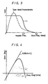
- the amplitude characteristic is expressed using a straight line coordinate system, as shown by a dashed line in Figure 3, the amplitude characteristic thereof becomes considerably different from that of an ideal filter.
- a digital signal equalizing circuit for a magnetic reproducing apparatus, the equalizing circuit comprising: a differentiating and integrating circuit in which an input signal is supplied to a differentiating circuit and an integrating circuit in parallel, and output signals of said differentiating circuit and said integrating circuit are subtracted from each other; a phase-shifting circuit; and a low-pass filter circuit; said differentiating and integrating circuit, said phase-shifting circuit and said low-pass filter circuit being connected in series.
- an embodiment of the present invention comprises a digital signal equalizing circuit in which a differentiating/integrating circuit, a phase-shifting circuit and a low-pass filter circuit are connected in series, whereby a desired frequency characteristic is produced in the whole of a recording and reproducing system.
- FIG 5 shows an embodiment of waveform equalizing circuit 10 in which a reproduced signal S PBIN from a playback amplifier circuit 4 (see Figure 1) is supplied to an integrating circuit 12 and to a differentiating circuit 14.
- the integrating circuit 12 is a primary integrating circuit whose frequency characteristic is set to be expressed by the following equation: Accordingly, as shown in Figure 2, the amplitude characteristic of the integrating circuit 12 is attenuated by -6 dB/oct in the frequency band higher than the frequency ⁇ 1.
- the differentiating circuit 14 is a primary differentiating circuit having the same order as that of the integrating circuit 12, and the frequency characteristic thereof is set to be expressed by the following equation: Accordingly, the amplitude characteristic of the differentiating circuit 14 is attenuated by -6 dB/oct in the frequency band lower than the frequency ⁇ 2.
- a subtracting circuit 16 subtracts an output signal of the differentiating circuit 14 from an output signal of the integrating circuit 12 and supplies a subtracted signal to a phase-shifting circuit 18.
- the subtracting circuit 16 derives an output signal having substantially an intermediate frequency between the frequencies ⁇ 1 and ⁇ 2 and whose amplitude is attenuated (see Figure 6).
- the phases of the signals are respectively changed by -90 and +90 degrees in the frequency band in which the amplitude characteristic is attenuated, so that, in the output signal from the subtracting circuit 16, the change of the phase can be complementarily compensated for, resulting in an output signal having the same phase characteristic as that of the reproduced signal S PBIN being produced.
- the phase-shifting circuit 18 phase-shifts the output signal of the subtracting circuit 16 by a predetermined phase as represented by the following equation:
- a low-pass filter circuit (LPF) 20 comprises a quaternary LPF as represented by the following equation and limits the band of the output signal of the phase-shifting circuit 18:
- the frequency characteristics of the LPF 20 is selected so as to generate a peak level in the high band, and the phase change, caused by the LPF 20, is compensated for by the phase-shifting circuit 18.
- the waveform equalizing circuit 10 presents a frequency characteristic H (s) expressed by the following equation:
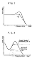
- the frequency characteristic of the waveform equalizing circuit 10 is selected such that, as shown Figures 8 and 9, the output signal of the subtracting circuit 16 is band-limited by the LPF 20, whereby the gain reaches a peak level near the frequency of 4.7 MHz (the Nyquist frequency) after the amplitude characteristic has decreased to a minimum at the frequency of substantially 1.5 MHz, and the gain is reduced substantially to zero at the frequency 9.4 MHz (that is the clock frequency, which is twice as high as the Nyquist frequency).
- the frequency characteristic H (s) of the waveform equalizing circuit must be selected to be the frequency characteristics H (s) expressed by the following equation: H R (s) and H D (s) represent the frequency characteristic of the ideal filter and the frequency characteristic of the electromagnetic transducing system, respectively.
- the ideal filter presents the frequency characteristic H R (s) which is flat in the frequency band lower than the Nyquist frequency and which is attenuated in the frequency band higher than the Nyquist frequency (see Figure 3)
- the electromagnetic transducing system presents the frequency characteristic H D (s) whose gain is attenuated in the high and low frequency bands
- the frequency characteristic H (s) of the waveform equalizing circuit expressed by the equation (6) is approximated to the frequency characteristic represented in Figure 9.
- the frequency characteristic of the waveform equalizing circuit is set so that the amplitude characteristic has the peak level near the Nyquist frequency and the amplitude characteristic is temporarily lowered near the frequency, 1.5 MHz, that is, lower than the Nyquist frequency, then the frequency characteristic of the overall recording and reproducing system can be determined to be a frequency characteristic quite similar to that of an ideal filter.
- the output signal of the differentiating circuit 14 is subtracted from the output signal of the integrating circuit 12, whereby the amplitude characteristic of the waveform equalizing circuit is temporarily lowered near the frequency 1.5 MHz.
- the output signal of the subtracting circuit 16 is limited in band by the quaternary LPF 20 to compensate for the overall frequency characteristic.
- the amplitude characteristic has a peak level near the Nyquist frequency.
- the output signal of the differentiating circuit 14 is subtracted from the output signal of the integrating circuit 12 temporarily to compensate for the phase changes of the output signals of the integrating circuit 12 and the differentiating circuit 14, so that, even when the amplitude characteristic is attenuated near the frequency of 1.5 MHz, the subtracting circuit 16 can derive a subtracted signal having a flat phase.
- the phase-shifting circuit 18 When the output signal of the subtracting signal 16 is limited in band by the LPF 20 to compensate for the overall amplitude characteristic, if the phase change, caused in compensating for the amplitude characteristic, is compensated for by the phase-shifting circuit 18, then the phase shift can be effectively avoided, and a frequency characteristic substantially the same as that of an ideal filter can be obtained.
- the integrating circuit 12, the differentiating circuit 14 and the subtracting circuit 16 form a differentiating/integrating circuit, wherein the differentiating circuit 14 and the integrating circuit 12 receive the input signal S PBIN in parallel and the output signal of the differentiating circuit 14 is subtracted from the output signal of the integrating circuit 12.
- the reproduced signal S PBIN from the playback amplifier circuit 4 is subtracted by the subtracting circuit 16 via the integrating circuit 12 and the differentiating circuit 14, and is thereby corrected to form the reproduced signal in which the amplitude characteristic thereof is increased in the high band after being temporarily lowered near the frequency of 1.5 MHz.
- the output signal from the subtracting circuit 16 is phase corrected in advance by the phase-shifting circuit 18 and the phase thereof is changed by that phase amount by the LPF 20, so being produced with a flat phase characteristic.
- the amplitude characteristics of the reproduced signal S PBIN is compensated so as to have a peak level near the Nyquist frequency (4.7 MHz) by the LPF 20, whereby the whole frequency characteristic of the recording and reproducing system is corrected to be substantially the frequency characteristic of the ideal filter.
- the primary integrating circuit and the primary differentiating circuit are used, the invention is not limited thereto. In short, if the orders of the integrating circuit and the differentiating circuit are made equal, then the phase characteristics can be made flat, and frequency characteristic approximate to that of an ideal filter can be obtained.
- phase characteristic can be determined as a desired characteristic, this can be realized by making the orders of the integrating circuit and the differentiating circuit different.
- the differentiating/integrating circuit the phase-shifting circuit and the low-pass filter circuit are connected in series in that order, the invention is not limited thereto, and the order thereof may be changed if necessary.
- the invention is applied to a digital audio tape recorded having a Nyquist frequency of 4.7 MHz, so that a frequency characteristic approximate to that of an ideal filter is obtained in the whole of the recording and reproducing system
- the invention is not limited to the frequency characteristic of an ideal filter and can be widely applied to the case in which the whole of the recording and reproducing system is set to a desired frequency characteristic.
- the invention is applied to a digital audio tape recorded so as to record a signal processed by the NRZI-coding method
- the invention is not limited thereto and can be widely applied to a magnetic reproducing apparatus for reproducing various digital signals.
Landscapes
- Engineering & Computer Science (AREA)
- Signal Processing (AREA)
- Digital Magnetic Recording (AREA)
- Signal Processing For Digital Recording And Reproducing (AREA)
Applications Claiming Priority (2)
| Application Number | Priority Date | Filing Date | Title |
|---|---|---|---|
| JP1305882A JP2770499B2 (ja) | 1989-11-25 | 1989-11-25 | 波形等化回路 |
| JP305882/89 | 1989-11-25 |
Publications (2)
| Publication Number | Publication Date |
|---|---|
| EP0430427A2 true EP0430427A2 (de) | 1991-06-05 |
| EP0430427A3 EP0430427A3 (en) | 1992-03-04 |
Family
ID=17950456
Family Applications (1)
| Application Number | Title | Priority Date | Filing Date |
|---|---|---|---|
| EP19900311606 Withdrawn EP0430427A3 (en) | 1989-11-25 | 1990-10-23 | Digital signal equalizing circuits |
Country Status (2)
| Country | Link |
|---|---|
| EP (1) | EP0430427A3 (de) |
| JP (1) | JP2770499B2 (de) |
Cited By (2)
| Publication number | Priority date | Publication date | Assignee | Title |
|---|---|---|---|---|
| CN108872957A (zh) * | 2017-05-11 | 2018-11-23 | 通用汽车环球科技运作有限责任公司 | 提升i-q线性频率调制雷达的分辨率和范围 |
| CN110332068A (zh) * | 2019-06-20 | 2019-10-15 | 贝德科技有限公司 | 一种超级电容柴油机泵低温启动装置 |
Families Citing this family (1)
| Publication number | Priority date | Publication date | Assignee | Title |
|---|---|---|---|---|
| JP3351163B2 (ja) * | 1994-07-27 | 2002-11-25 | 株式会社日立製作所 | 情報記録再生装置及び信号処理回路 |
Family Cites Families (3)
| Publication number | Priority date | Publication date | Assignee | Title |
|---|---|---|---|---|
| US4110798A (en) * | 1977-01-26 | 1978-08-29 | Ampex Corporation | Frequency response equalizer |
| JPS62219806A (ja) * | 1986-03-20 | 1987-09-28 | Sanyo Electric Co Ltd | 波形等価器 |
| DE3717981A1 (de) * | 1987-05-27 | 1988-12-08 | Tandberg Data | Verfahren und schaltungsanordnung zum umsetzen von analogsignalen in binaersignale |
-
1989
- 1989-11-25 JP JP1305882A patent/JP2770499B2/ja not_active Expired - Fee Related
-
1990
- 1990-10-23 EP EP19900311606 patent/EP0430427A3/en not_active Withdrawn
Cited By (2)
| Publication number | Priority date | Publication date | Assignee | Title |
|---|---|---|---|---|
| CN108872957A (zh) * | 2017-05-11 | 2018-11-23 | 通用汽车环球科技运作有限责任公司 | 提升i-q线性频率调制雷达的分辨率和范围 |
| CN110332068A (zh) * | 2019-06-20 | 2019-10-15 | 贝德科技有限公司 | 一种超级电容柴油机泵低温启动装置 |
Also Published As
| Publication number | Publication date |
|---|---|
| JPH03168904A (ja) | 1991-07-22 |
| EP0430427A3 (en) | 1992-03-04 |
| JP2770499B2 (ja) | 1998-07-02 |
Similar Documents
| Publication | Publication Date | Title |
|---|---|---|
| EP0141424B1 (de) | Tonsignalübertragungssystem mit Geräuschunterdrückung | |
| US4637036A (en) | Circuit arrangement for a data acquisition circuit of a PCM processor and a method for improving waveform of PCM signal eye pattern | |
| EP0183186B1 (de) | Vorrichtung zur Aufnahme und Wiedergabe von Videosignalen und digitalen, von Videosignalen verschiedenen, Signalen | |
| KR960016898B1 (ko) | 디지탈 신호의 전송계에 있어서 손실된 저주파수 성분을 재생하여 보상하기 위한 직류 재생회로 | |
| EP0385867A2 (de) | Wiedergabegerät für ein digitales Signal | |
| PL163950B1 (pl) | Urzadzenie do zapisu na tasmie magnetycznej PL PL PL | |
| DE3853187T2 (de) | Aufzeichnungsgerät für Informationen. | |
| EP0430427A2 (de) | Entzerrerschaltung für digitale Signale | |
| EP0365330B1 (de) | Vorrichtung zur magnetischen Wiedergabe | |
| US4317144A (en) | Azimuth correction of head gaps | |
| JPH027203A (ja) | 再生等化回路 | |
| EP0465159A2 (de) | Datenaufzeichnungsgerät | |
| US5103349A (en) | Process for directly copying frequency modulated video signals from magnetic tape to magnetic tape | |
| US5663844A (en) | Signal reproducing apparatus having waveform equalizing function | |
| EP0104701B1 (de) | Gerät zur Wiedergabe von einem Aufzeichnungsträger | |
| JPS63133357A (ja) | 信号処理回路 | |
| US6445526B1 (en) | Reproducing apparatus capable of controlling amplitude and phase characteristics of reproduced signals | |
| HK108290A (en) | Method of recording pcm audio transmission signals with signal error compensation | |
| JP3123680B2 (ja) | エンフアシス回路及びその製造方法 | |
| EP0453684A2 (de) | Entzerrer beim Abspielen eines Bandaufzeichnungsgeräts | |
| EP0488811B1 (de) | Magnetisches Aufzeichnungs- und Wiedergabegerät | |
| EP0387804B1 (de) | Aufzeichnung eines frequenzmodulierten Signals auf einem Aufzeichnungsmedium | |
| EP0147073A1 (de) | Schaltung zur Rauschverminderung für ein Videosignal | |
| CA1078063A (en) | Noise reduction circuit | |
| JPS63133358A (ja) | 信号処理回路 |
Legal Events
| Date | Code | Title | Description |
|---|---|---|---|
| PUAI | Public reference made under article 153(3) epc to a published international application that has entered the european phase |
Free format text: ORIGINAL CODE: 0009012 |
|
| AK | Designated contracting states |
Kind code of ref document: A2 Designated state(s): DE FR GB |
|
| PUAL | Search report despatched |
Free format text: ORIGINAL CODE: 0009013 |
|
| AK | Designated contracting states |
Kind code of ref document: A3 Designated state(s): DE FR GB |
|
| 17P | Request for examination filed |
Effective date: 19920710 |
|
| STAA | Information on the status of an ep patent application or granted ep patent |
Free format text: STATUS: THE APPLICATION IS DEEMED TO BE WITHDRAWN |
|
| 18D | Application deemed to be withdrawn |
Effective date: 19940503 |