EP0430515A2 - Erbium-dotierte Faserverstärker - Google Patents
Erbium-dotierte Faserverstärker Download PDFInfo
- Publication number
- EP0430515A2 EP0430515A2 EP90312520A EP90312520A EP0430515A2 EP 0430515 A2 EP0430515 A2 EP 0430515A2 EP 90312520 A EP90312520 A EP 90312520A EP 90312520 A EP90312520 A EP 90312520A EP 0430515 A2 EP0430515 A2 EP 0430515A2
- Authority
- EP
- European Patent Office
- Prior art keywords
- fiber
- pump
- core
- optical amplifier
- radius
- Prior art date
- Legal status (The legal status is an assumption and is not a legal conclusion. Google has not performed a legal analysis and makes no representation as to the accuracy of the status listed.)
- Withdrawn
Links
Images

Classifications
-
- H—ELECTRICITY
- H01—ELECTRIC ELEMENTS
- H01S—DEVICES USING THE PROCESS OF LIGHT AMPLIFICATION BY STIMULATED EMISSION OF RADIATION [LASER] TO AMPLIFY OR GENERATE LIGHT; DEVICES USING STIMULATED EMISSION OF ELECTROMAGNETIC RADIATION IN WAVE RANGES OTHER THAN OPTICAL
- H01S3/00—Lasers, i.e. devices using stimulated emission of electromagnetic radiation in the infrared, visible or ultraviolet wave range
- H01S3/05—Construction or shape of optical resonators; Accommodation of active medium therein; Shape of active medium
- H01S3/06—Construction or shape of active medium
- H01S3/063—Waveguide lasers, i.e. whereby the dimensions of the waveguide are of the order of the light wavelength
- H01S3/067—Fibre lasers
- H01S3/06754—Fibre amplifiers
-
- H—ELECTRICITY
- H01—ELECTRIC ELEMENTS
- H01S—DEVICES USING THE PROCESS OF LIGHT AMPLIFICATION BY STIMULATED EMISSION OF RADIATION [LASER] TO AMPLIFY OR GENERATE LIGHT; DEVICES USING STIMULATED EMISSION OF ELECTROMAGNETIC RADIATION IN WAVE RANGES OTHER THAN OPTICAL
- H01S3/00—Lasers, i.e. devices using stimulated emission of electromagnetic radiation in the infrared, visible or ultraviolet wave range
- H01S3/05—Construction or shape of optical resonators; Accommodation of active medium therein; Shape of active medium
- H01S3/06—Construction or shape of active medium
- H01S3/063—Waveguide lasers, i.e. whereby the dimensions of the waveguide are of the order of the light wavelength
- H01S3/067—Fibre lasers
- H01S3/06708—Constructional details of the fibre, e.g. compositions, cross-section, shape or tapering
- H01S3/0672—Non-uniform radial doping
Definitions
- This invention relates generally to fiber amplifiers and more particularly to erbium-doped fiber amplifiers.
- the rare earth doped optical amplifying fibers are found to have low cost, exhibit low-noise, relatively large bandwidth which is not polarization dependent, substantially reduced crosstalk problems, and low insertion losses at the relevant operating wavelengths which are used in optical communications.
- Contemplated rare earth doped optical fiber amplifiers can be coupled end-to-end to a transmission fiber, and tranversely coupled, through a directional coupler, to a laser diode pump.
- the directional coupler is designed to have a high coupling ratio at the pump wavelength and a low coupling ratio at the signal wavelength so that maximum pump energy is coupled to the amplifier with minimal signal loss.
- the pump energy may be made to propagate either codirectionally or contra-directionally relative to the signal energy, depending upon whether any remaining unconverted pump light can be more conveniently filtered at the transmitter or the receiver.
- a complicating factor in the design of rare earth doped optical amplifiers involves the difference between the various parameters necessary to optimize the performance of the amplifier and those necessary to optimize the performance of the associated transmission fibers. These differences, which arise from the different functions performed by the optical amplifier and the transmission fiber, result in significant signal loss as the signal is transmitted from the transmission fiber to the amplifying fiber, and therefore place a premium on the efficiency of the amplifying fiber which restores the signal to its previous levels.
- waveguide dispersion must be minimized in order to maximize bandwidth and minimize loss, thereby maximizing the spacing between repeaters.
- the major concern involves high gain,high saturation power, and low noise, all with minimal pump powers. Exemplary signal losses that can occur because of the different optimal parameters for the transmission and amplifying fibers are splicing losses due to mode mismatch because the signal mode size may be significantly different for these two fibers.
- This invention is a rare earth doped optical amplifier with increased gain and lowered pump thresholds.
- the amplifying scheme is based on a 3 level lasing system rather than the more prevalent 4 level lasing system.
- the transmission mode of the optical fiber at the pump wavelength has a radius which is substantially equal to or greater than the radius of the distribution profile of the rare earth ions in the fiber amplifier core.
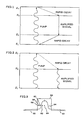
- FIG.1 is on energy level diagram showing population inversion and lasing for a non-semiconductor four level system
- FIG.2 is an energy level diagram showing population inversion and lasing for a non-semiconductor three level system
- FIG.3 is a plot of the index of refraction of an erbium-doped fiber superimposed on a plot of the intensity profile of the pump mode of prior art optical amplifier;
- FIG.4 is a schematic diagram of structure for testing the erbium doped fiber amplifier.
- FIG.6 is a plot of the index of refraction of an erbium-doped fiber superimposed on a plot of the intensity profile of the pump mode in accordance with the principles of the invention.
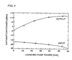
- FIG.7 is a plot of input and output signal saturation powers as a function of the launched pump power.
- Rare earth doped fibers for amplifying weak signals for both local and trunk optical telecommunications networks are of particular interest because of their low insertion loss, broad gain bandwidth and polarization insensitive gain.
- the doped optical fiber is normally traversely coupled to a pump so that a weak optical input signal at some wavelength within the rare earth gain profile experiences a desired amplification.
- Pump light which can be coupled into the optical fiber via a directional coupler may propagate either co-directionally or contra-directionally within the fiber relative to the signal.
- the directional coupler can have a high coupling ratio at the pump wavelength and a low coupling ratio at the signal wavelength.
- the fiber When the fiber is not pumped, the signal experiences loss due to ground state absorption by the rare earth ions. As the pump power that is aplied to the fiber is increased, the loss due to ground level absorption decreases (i.e. gain is negative but increasing) until, at some value of pump power, there is no neg signal absorption (i.e. the gain is zero). This is referred to as the transparency state. Thereafter, as the pump power in the fiber is increased, a higher proportion of rare earth ions are in their excited state and the stimulated emission from the upper lasing state to the ground state becomes stronger than the absorption from the ground state to the upper lasing state, resulting in a net positive gain at various wavelengths. Thus, the opticla amplifier, when pumped so as to populate the upper lasing level, produces a net positive gain above the pump threshold level and the fiber acts as an amplifier.
- FIG.1 illustrates a 4 level lasing system
- FIG.2 illustrates a 3 level lasing system.
- pumping is effected by a separate laser or lamp which emits photons of an appropriate energy which is higher than that which corresponds to the signal wavelength.
- the electrons are excited from the ground state to one or more pump bands which are above the upper lasing level.
- a pump band can comprise a multiplet state in the Stark manifold.
- electronic states In the case of an ion in a glass, electronic states generally are broadened into Stark split manifolds.
- the different manifold multiplet states are usually not really discrete levels at room temperature because of homogeneous broadening.
- the electrons are excited to a level of the upper lasing state, and this level can be above level E4 of FIG.1 and E3 of FIG.2.
- the electrons then decay, normally nonradiatively from this level, to the upper lasing level. It is important that the spontaneous life time of the upper lasing level exceed that of the pump bands by a significant margin to allow heavy population of the upper level.
- stimulated emission can occur. The photon can come from either previous spontaneous emission, stimulated emission, or an input signal.
- the difference between the 4 level lasing system of FIG.1 and the 3 level lasing system of FIG. 2 is important to note.
- the lower lasing level is either the ground state or so close to the ground state that it has a significant thermal population.
- the 4 level lasing system there is still a further transition from the lower lasing level to the ground state, and this is normally nonradiative in nature and much faster than the radiative transition.
- absorption from the ground state directly to the upper lasing level takes place, decreasing the signal intensity and vitiating the effect of emission of lasing photons unless the ground state is depopulated by strong pumping.
- 3 level laser systems normally have higher values of threshold power than 4 level laser systems, especially for bulk, non-fiber active media and, therefore,4 level laser systems are currently preferred.
- Rare earth doped optical fiber amplifiers operate in both 3 and 4 level modes.
- erbium-doped fiber amplifiers have high threshold powers which are obtained because the cores are large relative to the power mode size.
- FIG.3 there is illustrated a plot of a prior art erbium-doped fiber amplifier having a high pump threshold.
- the center step portion 50 represents the index of refraction of the erbium-doped core of the single mode fiber and the ends 52 represent the index of refraction of the cladding of the single mode fiber.
- the core of the optical fiber which can be made from glass and, therefore, is referred to as the glass host is uniformly doped with the rare earth dopant erbium and the index of refraction of the core is greater than that of the cladding.
- the curve of the pump mode 54 of the fiber is illustratively superimposed on the plot of the index of refraction of the optical fiber.
- the radius of the core 50 of the erbium-doped fiber is large compared to the radius of the pump mode 54 of the fiber.
- Included in FIG.3 are representative atoms 56,58,60,62,64 of erbium which may be substantially uniformly distributed across the core.
- erbium atoms 62 and 64 are near or at the center of the fiber and are exposed to the maximum intensity of the pump mode. Obviously they are excited from the ground state to a band which is above the upper lasing level. This, however, does not occur for those erbium atoms 56,58, 60 which are positioned near the edge of the core.
- the intensity of the mode at and near the edge of the core is substantially reduced relative to the peak value at the center of the core.
- this reduction may be such that the erbium atoms at the edge of the core do not see a sufficient flux of pump photons to yield a net gain.
- Such atoms contribute only to signal absorption which reduces the overall fiber gain experienced by the signal mode.
- the lower lasing level is either the ground state or at a level so close to the ground state that it has a significant thermal population.
- atoms of erbium 56,58,60 located in the low intensity area spend most of their time at the lower lasing level, not only do they not materially contribute to the gain process, but they contribute to absorption, decreasing the efficiency of the amplifier.
- atoms in the low pump region spend most of their time in the ground state which is not the lower lasing state thus they are just passive observers; they do not participate in the gain, but contrary to the case of the 3 level system, they do not absorb at the signal wavelength either and thus do not degrade the gain.
- a 4 level lasing system it is desirable to have a large cavity to keep the signal intensities below the saturation intensity to achieve a high saturation output power.
- Corresponding saturation output powers of +2.5dBm to +11dBm have been achieved.
- For the 54mW launched pump power a high saturation output signal power of +11dBm has been measured. This is a dramatic improvement over the +2.5dBm value previously reported for this pump wavelength.
- the erbium-doped fiber amplifier which provides the above mentioned results has a core radius of 1.81 ⁇ m and a Numerical Aperture of 0.23.
- FIG.4 there is illustrated a schematic of a test setup for testing the erbium-doped fiber amplifier.
- a trade-off between maximum output power for the color-center laser 10 and the operating wavelength resulted in this specific pump wavelength being selected as being optimal. It is to be understood, however, that this laser may not represent the optimal pump wavelength for achieving the highest erbium-doped fiber amplifier gains.
- a Faraday isolator 16 is used to prevent feedback from backward ASE onto the signal laser and also prevents feedback from reflections into the erbium-doped fiber amplifier.
- a fiber pig-tail 18 with low-reflectivity index-matching windows is placed between the external cavity laser diode 14 and the Faraday isolator 16. Maximization of the signal passing through the Faraday isolator is achieved through a fiber polarization controller 20 placed onto the pig-tail.
- the erbium doped fiber amplifier 24 is butt-spliced at 26 to the straight through output fiber of coupler 28 which uses index-matching oil 29 to suppress unwanted reflections and Fabry Perot effects.
- the output end 30 of the erbium-doped fiber is polished at a ten degree angle to prevent feedback into the erbium-doped fiber amplifier.
- the 1% output port 32 of the coupler is used to monitor the pump and signal input to the erbium-doped fiber amplifier.
- the end, 34, of the coupler input fiber lead is also polished at a ten degree angle to prevent feedback.
- the other input lead which is not used is index-matched for that same purpose.
- the coupling ratio between the input fiber lead and the fiber amplifier which was measured to be ⁇ 0.63, corresponds to -2.0dB coupling loss.
- this coupling loss is due to the slight mismatch between the mode envelopes of the amplifier fiber and the coupler fiber, to yield a non-optimized overlap integral.
- the output of the erbium-doped fiber amplifier is directed either to a spectrometer to monitor the amplified signal or to a power meter for gain measurements.
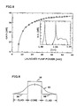
- the signal gain G as a function of pump power P in p launched into the erbium-doped fiber amplifier is illustrated in FIG.5.
- the fiber used to obtain the illustrated results has a length of 47.5m.
- the input pump power required to achieve transparency for long fiber lengths is higher than the pump threshold which is required for medium inversion which is due to the pump decay along the fiber, illustrates that the fiber actually has a low inversion threshold.
- a maximum gain of +36.8 + 0.3dB is achieved with 53.6mW launched pump power, which is slightly more than the highest gains of +35dB reported for Erbium-doped fiber amplifiers when pumped with visible light and about 10dB higher than the gains when pumped at 1.49 ⁇ m as reported in the Optical Fiber Communication Conference, 1989, Technical Digest Series, PD15-1 by K. Hagimoto et al.
- the improvement is attributed to the very low pump threshold of the fiber, which is a consequence of the small size of the pump mode.
- the pump threshold should be as low as possible to obtain improved efficiency.
- FIG. 6 is a plot of the index of refraction of an erbium-doped fiber amplifier in accordance with the principles of the invention wherein the fiber is designed to have a low pump threshold.
- the center step portion 36 represents the index of refraction of the erbium-doped core of the single mode fiber and the ends 38, represent the index of refraction of the cladding of the single mode fiber.
- the core of the optical fiber contains the erbium and the index of refraction of the core is greater than that of the cladding.
- the curve of the pump mode 42 of the fiber is illustratively superimposed on the plot of the index of refraction of the optical fiber.
- the radius of the core 36 of the erbium-doped fiber is equal to or less than to the radius of the pump mode of the fiber.
- the radius of the erbium-doped core is equal to or less than the radius of the pump mode of the fiber, each atom of erbium in the core cross-section is exposed to substantially equal levels of the high intensity portion of the pump mode.
- a high operating efficiency is obtain when the core has a radius of 1.8 ⁇ m, and when the differential of the index of refraction of the core relative to the cladding is substantially 0.019, and the power mode size ⁇ of the pump does not exceed substantially 3 ⁇ m.
- FIG.7 there is illustrated the input and output signal saturation powers which result in 3dB gain compression as a function of the launched pump power.
- the FIG. shows that, as the pump is increased, the input saturation power decreases and the output saturation power increases.
Landscapes
- Physics & Mathematics (AREA)
- Electromagnetism (AREA)
- Engineering & Computer Science (AREA)
- Plasma & Fusion (AREA)
- Optics & Photonics (AREA)
- Lasers (AREA)
- Optical Fibers, Optical Fiber Cores, And Optical Fiber Bundles (AREA)
- Light Guides In General And Applications Therefor (AREA)
Applications Claiming Priority (2)
| Application Number | Priority Date | Filing Date | Title |
|---|---|---|---|
| US07/441,495 US5005175A (en) | 1989-11-27 | 1989-11-27 | Erbium-doped fiber amplifier |
| US441495 | 1989-11-27 |
Publications (2)
| Publication Number | Publication Date |
|---|---|
| EP0430515A2 true EP0430515A2 (de) | 1991-06-05 |
| EP0430515A3 EP0430515A3 (en) | 1991-09-18 |
Family
ID=23753097
Family Applications (1)
| Application Number | Title | Priority Date | Filing Date |
|---|---|---|---|
| EP19900312520 Withdrawn EP0430515A3 (en) | 1989-11-27 | 1990-11-16 | Erbium-doped fiber amplifier |
Country Status (3)
| Country | Link |
|---|---|
| US (1) | US5005175A (de) |
| EP (1) | EP0430515A3 (de) |
| JP (1) | JP2971561B2 (de) |
Cited By (1)
| Publication number | Priority date | Publication date | Assignee | Title |
|---|---|---|---|---|
| EP0452669B1 (de) * | 1990-03-16 | 1996-02-21 | Alcatel N.V. | Erbium-dotierter optischer Faserverstärker |
Families Citing this family (67)
| Publication number | Priority date | Publication date | Assignee | Title |
|---|---|---|---|---|
| JP3137632B2 (ja) * | 1989-08-31 | 2001-02-26 | 富士通株式会社 | 光ファイバ増幅器を備えた光通信方式 |
| IT1238333B (it) * | 1990-01-22 | 1993-07-12 | Pirelli Cavi Spa | Amplificatore ottico di potenza a fibra attiva drogata |
| US5638204A (en) * | 1990-01-22 | 1997-06-10 | Pirelli Cavi S.P.A. | Optical power amplifier with Al2 O3 and erbium doped active fiber |
| DE4002369A1 (de) * | 1990-01-27 | 1991-08-01 | Standard Elektrik Lorenz Ag | Mehrstufiger faseroptischer verstaerker |
| GB9007912D0 (en) * | 1990-04-06 | 1990-06-06 | British Telecomm | A method of forming a refractive index grating in an optical waveguide |
| JPH041614A (ja) * | 1990-04-18 | 1992-01-07 | Mitsubishi Electric Corp | 光増幅装置 |
| DE4014034A1 (de) * | 1990-05-02 | 1991-11-07 | Standard Elektrik Lorenz Ag | Optischer verstaerker |
| GB9016181D0 (en) * | 1990-07-24 | 1990-09-05 | British Telecomm | Optical waveguide amplifier |
| US5155621A (en) * | 1990-07-31 | 1992-10-13 | Fujitsu Limited | Optical fiber amplifier |
| US5185749A (en) * | 1990-09-18 | 1993-02-09 | The Board Of Trustee Of The Leland Stanford Junior University | Large signal three-level superfluorescent fiber sources |
| US5088095A (en) * | 1991-01-31 | 1992-02-11 | At&T Bell Laboratories | Gain stabilized fiber amplifier |
| DE4106778A1 (de) * | 1991-03-04 | 1992-09-10 | Standard Elektrik Lorenz Ag | Optisch-elektrisch-wandler mit erweitertem dynamikbereich |
| US5200029A (en) * | 1991-04-25 | 1993-04-06 | At&T Bell Laboratories | Method of making a planar optical amplifier |
| US5119460A (en) * | 1991-04-25 | 1992-06-02 | At&T Bell Laboratories | Erbium-doped planar optical device |
| US5107538A (en) * | 1991-06-06 | 1992-04-21 | At&T Bell Laboratories | Optical waveguide system comprising a rare-earth Si-based optical device |
| JPH0566430A (ja) * | 1991-09-06 | 1993-03-19 | Ando Electric Co Ltd | 高出力光パルス発生器 |
| US5283847A (en) * | 1991-09-09 | 1994-02-01 | Sumitomo Electric Industries, Ltd. | Method of manufacturing and evaluating an optical fiber coupler and apparatus therefor |
| US5227913A (en) * | 1991-09-11 | 1993-07-13 | Wisconsin Alumni Research Foundation | Co-deposition of erbium and titanium into lithium niobate and optical amplifier produced thereby |
| JP2677726B2 (ja) * | 1991-09-20 | 1997-11-17 | 富士通株式会社 | 光送信機 |
| US5343320A (en) * | 1992-08-03 | 1994-08-30 | At&T Bell Laboratories | Pump laser control circuit for an optical transmission system |
| US5223705A (en) * | 1992-08-12 | 1993-06-29 | At&T Bell Laboratories | Measurement of an optical amplifier parameter with polarization |
| IL106766A (en) * | 1992-08-28 | 1995-12-31 | Hughes Aircraft Co | Bi-directional optical fiber amplifier for missile guidance data link repeater |
| GB2273389B (en) * | 1992-12-14 | 1996-07-17 | Pirelli Cavi Spa | Rare earth doped optical fibre amplifiers |
| DE4315846A1 (de) * | 1993-03-30 | 1994-10-06 | Sel Alcatel Ag | Faseroptischer Verstärker |
| US5448579A (en) * | 1993-12-09 | 1995-09-05 | Hewlett-Packard Company | Polarization independent picosecond fiber laser |
| US5689519A (en) * | 1993-12-20 | 1997-11-18 | Imra America, Inc. | Environmentally stable passively modelocked fiber laser pulse source |
| US5572541A (en) * | 1994-10-13 | 1996-11-05 | Coherent Technologies, Inc. | Laser rod assembly for side pumped lasers |
| US5657153A (en) * | 1995-03-21 | 1997-08-12 | Sdl, Inc. | Optical amplifier with complementary modulation signal inputs |
| US5563979A (en) * | 1995-08-31 | 1996-10-08 | Lucent Technologies Inc. | Erbium-doped planar optical device |
| JP3556379B2 (ja) | 1996-03-07 | 2004-08-18 | 富士通株式会社 | 光伝送システム |
| US5815309A (en) * | 1997-01-21 | 1998-09-29 | Molecular Optoelectronics Corporation | Optical amplifier and process for amplifying an optical signal propagating in a fiber optic |
| US5982961A (en) * | 1997-01-21 | 1999-11-09 | Molecular Optoelectronics Corporation | Organic crystal compound optical waveguide and methods for its fabrication |
| US6198569B1 (en) | 1998-02-20 | 2001-03-06 | Molecular Optoelectronics Corporation | Multiple window dense wavelength divison multiplexed communications link with optical amplification and dispersion compensation |
| CA2299236A1 (en) * | 1998-02-20 | 1999-08-26 | Brian L. Lawrence | Optical amplifier and process for amplifying an optical signal propagating in a fiber optic employing an overlay waveguide and stimulated emission |
| US6034975A (en) * | 1998-03-09 | 2000-03-07 | Imra America, Inc. | High power, passively modelocked fiber laser, and method of construction |
| US6270604B1 (en) | 1998-07-23 | 2001-08-07 | Molecular Optoelectronics Corporation | Method for fabricating an optical waveguide |
| JP2000068929A (ja) * | 1998-08-17 | 2000-03-03 | Tsutomu Kimura | 光通信システム |
| US6545799B1 (en) | 1998-09-02 | 2003-04-08 | Corning Incorporated | Method and apparatus for optical system link control |
| US6236793B1 (en) | 1998-09-23 | 2001-05-22 | Molecular Optoelectronics Corporation | Optical channel waveguide amplifier |
| US6275512B1 (en) * | 1998-11-25 | 2001-08-14 | Imra America, Inc. | Mode-locked multimode fiber laser pulse source |
| US6538805B1 (en) | 1999-02-19 | 2003-03-25 | Photon-X, Inc. | Codopant polymers for efficient optical amplification |
| US6292292B1 (en) | 2000-02-18 | 2001-09-18 | Photon-X | Rare earth polymers, optical amplifiers and optical fibers |
| US20040201000A1 (en) * | 1999-02-19 | 2004-10-14 | Photon-X, Inc. | Polymer blends for optical amplification |
| US6208456B1 (en) | 1999-05-24 | 2001-03-27 | Molecular Optoelectronics Corporation | Compact optical amplifier with integrated optical waveguide and pump source |
| US6353497B1 (en) | 2000-03-03 | 2002-03-05 | Optical Coating Laboratory, Inc. | Integrated modular optical amplifier |
| US7088756B2 (en) * | 2003-07-25 | 2006-08-08 | Imra America, Inc. | Polarization maintaining dispersion controlled fiber laser source of ultrashort pulses |
| US7190705B2 (en) | 2000-05-23 | 2007-03-13 | Imra America. Inc. | Pulsed laser sources |
| JP2002009376A (ja) * | 2000-06-23 | 2002-01-11 | Furukawa Electric Co Ltd:The | 光増幅用光ファイバ |
| CN1274618C (zh) | 2001-02-02 | 2006-09-13 | 信息技术部 | 掺杂稀土的光导纤维的制备方法 |
| US6724528B2 (en) | 2001-02-27 | 2004-04-20 | The United States Of America As Represented By The Secretary Of The Navy | Polarization-maintaining optical fiber amplifier employing externally applied stress-induced birefringence |
| US6751990B2 (en) | 2001-03-06 | 2004-06-22 | Council Of Scientific And Industrial Research | Process for making rare earth doped optical fiber |
| US6819846B2 (en) * | 2001-08-02 | 2004-11-16 | Corning Incorporated | High absorption erbium doped amplifying optical fiber |
| EP1441991B1 (de) | 2001-10-18 | 2006-02-08 | Council of Scientific and Industrial Research | Verfahren zur herstellung einer mit seltenen erden dotierten optischen faser |
| AU2003202227A1 (en) * | 2002-01-08 | 2003-07-24 | Photon-X, Inc. | Optical waveguide amplifiers |
| US6947208B2 (en) * | 2002-01-25 | 2005-09-20 | John Ballato | Optical fiber amplifier with fully integrated pump source |
| US20030194162A1 (en) * | 2002-03-26 | 2003-10-16 | Mininni Robert M. | Fluorinated and halogenated phosphinic acids and their active metal derivatives |
| US6851281B2 (en) * | 2002-03-28 | 2005-02-08 | Council Of Scientific And Industrial Research | Method of fabricating rare earth doped optical fibre |
| US7046902B2 (en) * | 2003-09-30 | 2006-05-16 | Coractive High-Tech Inc. | Large mode field diameter optical fiber |
| US7804864B2 (en) | 2004-03-31 | 2010-09-28 | Imra America, Inc. | High power short pulse fiber laser |
| US7999999B2 (en) * | 2004-10-29 | 2011-08-16 | Unopsys, Llc | Article comprising a multichannel optical amplified transmission system with functional upgrade capabilities and universal modules |
| US7116472B2 (en) * | 2005-02-18 | 2006-10-03 | Fitel Usa Corp. | Rare-earth-doped optical fiber having core co-doped with fluorine |
| US7945158B2 (en) * | 2006-08-18 | 2011-05-17 | Tellabs Operations, Inc. | Transponder-less verification of the configuration of an optical network node |
| JP5204975B2 (ja) * | 2007-01-25 | 2013-06-05 | 株式会社東芝 | ファイバ増幅器 |
| US20090059352A1 (en) * | 2007-08-30 | 2009-03-05 | Furukawa Electric North America, Inc. | Method and arrangement for mitigating bend distortion impact in a fiber amplifier or laser |
| JP5018492B2 (ja) * | 2008-01-15 | 2012-09-05 | 住友電気工業株式会社 | プリフォーム製造方法 |
| US9683830B2 (en) * | 2014-10-29 | 2017-06-20 | Honeywell International Inc | Compensated broadband fiber light source with stable mean wavelength |
| US11489311B2 (en) * | 2019-10-22 | 2022-11-01 | Lumentum Operations Llc | Optical amplifier |
Family Cites Families (3)
| Publication number | Priority date | Publication date | Assignee | Title |
|---|---|---|---|---|
| US4780877A (en) * | 1985-07-26 | 1988-10-25 | Polaroid Corporation | Optical fiber laser |
| GB8724736D0 (en) * | 1987-10-22 | 1987-11-25 | British Telecomm | Optical fibre |
| US4860295A (en) * | 1988-12-12 | 1989-08-22 | The United States Of America As Represented By The Administrator Of The National Aeronautics And Space Administration | Cladding for transverse-pumped solid-state laser |
-
1989
- 1989-11-27 US US07/441,495 patent/US5005175A/en not_active Expired - Lifetime
-
1990
- 1990-11-16 EP EP19900312520 patent/EP0430515A3/en not_active Withdrawn
- 1990-11-27 JP JP2321388A patent/JP2971561B2/ja not_active Expired - Fee Related
Cited By (1)
| Publication number | Priority date | Publication date | Assignee | Title |
|---|---|---|---|---|
| EP0452669B1 (de) * | 1990-03-16 | 1996-02-21 | Alcatel N.V. | Erbium-dotierter optischer Faserverstärker |
Also Published As
| Publication number | Publication date |
|---|---|
| JP2971561B2 (ja) | 1999-11-08 |
| US5005175A (en) | 1991-04-02 |
| JPH03188687A (ja) | 1991-08-16 |
| EP0430515A3 (en) | 1991-09-18 |
Similar Documents
| Publication | Publication Date | Title |
|---|---|---|
| US5005175A (en) | Erbium-doped fiber amplifier | |
| US5027079A (en) | Erbium-doped fiber amplifier | |
| EP0540602B1 (de) | Optischer wellenleiterverstärker | |
| US5623362A (en) | Erbium-doped fiber amplifier and an optical fiber communication system | |
| KR100686417B1 (ko) | 이득 평탄화 필터를 가진 광섬유 증폭기 | |
| EP0588557A1 (de) | Symmetrischer optischer Verstärker | |
| KR100334778B1 (ko) | 피드 백 루프를 이용한 장파장 대역 광섬유 증폭기 | |
| CN1246641A (zh) | 提高功率转换效率的长频带光纤放大器 | |
| US6535329B1 (en) | Temperature tuning an optical amplifier | |
| KR100258970B1 (ko) | 광섬유 증폭기 | |
| Dung et al. | Gain flattening of erbium-doped fibre amplifier using fibre Bragg gratings | |
| US20010022884A1 (en) | C-band multimode cladding optical fiber amplifier | |
| KR20010041602A (ko) | 초광대역의 저-노이즈 게인-플랫된 희토류 도프처리된섬유 증폭기 | |
| US6583922B2 (en) | Optical amplifier site with reduced noise and transmission system utilizing such | |
| Smart et al. | An investigation of the noise figure and conversion efficiency of 0.98 mu m pumped erbium-doped fiber amplifiers under saturated conditions | |
| KR100269170B1 (ko) | 광섬유 반사체를 이용한 광섬유증폭기 | |
| EP0944939B1 (de) | Faserverstärker mit verringerter verzerrung des flachen, temperaturabhängigen verstärkerprofils | |
| US6847769B1 (en) | Optical fiber amplifier | |
| Segi et al. | Silica-based composite fiber amplifier with 1480-1560 nm seamless gain-band | |
| KR100219711B1 (ko) | 평탄한 이득특성을 갖는 광섬유증폭기 | |
| Qian et al. | Erbium-doped phosphosilicate fiber amplifiers: a comparison of configurations for the optimization of noise figure and conversion efficiency | |
| JP2842674B2 (ja) | 光増幅装置 | |
| KR0183911B1 (ko) | 평탄한 고이득 및 낮은 잡음지수를 갖는 광섬유 증폭기 | |
| KR0183913B1 (ko) | 평탄한 고이득 및 낮은 잡음지수를 갖는 어븀도핑 광섬유 증폭기 | |
| Tachibana et al. | Spectral Gain Cross Saturation and Hole-Burning in Wideband Erbium-Doped Fibre Amplifiers |
Legal Events
| Date | Code | Title | Description |
|---|---|---|---|
| PUAI | Public reference made under article 153(3) epc to a published international application that has entered the european phase |
Free format text: ORIGINAL CODE: 0009012 |
|
| AK | Designated contracting states |
Kind code of ref document: A2 Designated state(s): DE FR GB |
|
| PUAL | Search report despatched |
Free format text: ORIGINAL CODE: 0009013 |
|
| AK | Designated contracting states |
Kind code of ref document: A3 Designated state(s): DE FR GB |
|
| 17P | Request for examination filed |
Effective date: 19920311 |
|
| 17Q | First examination report despatched |
Effective date: 19930323 |
|
| STAA | Information on the status of an ep patent application or granted ep patent |
Free format text: STATUS: THE APPLICATION IS DEEMED TO BE WITHDRAWN |
|
| 18D | Application deemed to be withdrawn |
Effective date: 19931005 |