EP0430564B1 - Schutzkappe für Gabelkopf - Google Patents
Schutzkappe für Gabelkopf Download PDFInfo
- Publication number
- EP0430564B1 EP0430564B1 EP90312667A EP90312667A EP0430564B1 EP 0430564 B1 EP0430564 B1 EP 0430564B1 EP 90312667 A EP90312667 A EP 90312667A EP 90312667 A EP90312667 A EP 90312667A EP 0430564 B1 EP0430564 B1 EP 0430564B1
- Authority
- EP
- European Patent Office
- Prior art keywords
- legs
- protective cover
- component
- shoulders
- end portion
- Prior art date
- Legal status (The legal status is an assumption and is not a legal conclusion. Google has not performed a legal analysis and makes no representation as to the accuracy of the status listed.)
- Expired - Lifetime
Links
Images
Classifications
-
- F—MECHANICAL ENGINEERING; LIGHTING; HEATING; WEAPONS; BLASTING
- F16—ENGINEERING ELEMENTS AND UNITS; GENERAL MEASURES FOR PRODUCING AND MAINTAINING EFFECTIVE FUNCTIONING OF MACHINES OR INSTALLATIONS; THERMAL INSULATION IN GENERAL
- F16D—COUPLINGS FOR TRANSMITTING ROTATION; CLUTCHES; BRAKES
- F16D3/00—Yielding couplings, i.e. with means permitting movement between the connected parts during the drive
- F16D3/16—Universal joints in which flexibility is produced by means of pivots or sliding or rolling connecting parts
-
- B—PERFORMING OPERATIONS; TRANSPORTING
- B65—CONVEYING; PACKING; STORING; HANDLING THIN OR FILAMENTARY MATERIAL
- B65D—CONTAINERS FOR STORAGE OR TRANSPORT OF ARTICLES OR MATERIALS, e.g. BAGS, BARRELS, BOTTLES, BOXES, CANS, CARTONS, CRATES, DRUMS, JARS, TANKS, HOPPERS, FORWARDING CONTAINERS; ACCESSORIES, CLOSURES, OR FITTINGS THEREFOR; PACKAGING ELEMENTS; PACKAGES
- B65D59/00—Plugs, sleeves, caps, or like rigid or semi-rigid elements for protecting parts of articles or for bundling articles, e.g. protectors for screw-threads, end caps for tubes or for bundling rod-shaped articles
- B65D59/06—Caps
Definitions
- This invention relates in general to protective devices and in particular to a protective cover which is releasably securable to an end yoke.
- the end yoke has a splined bore formed through a hub portion which permits it to be mounted on a splined shaft for rotation therewith.
- the end yoke is mounted on the output shaft of a vehicle transmission.
- the end yoke further has a pair of spaced apart arms which form a portion of a universal joint.
- the universal joint provides a variable angular driving connection between the output shaft and a drive shaft.
- the outer surface of the hub portion of the end yoke is usually formed having a precisely ground outer surface for engagement by a seal.
- DE-A-7912106 describes a protective cover having a plurality of legs depending from a cover portion.
- the legs are spaced apart and form an annular sleeve which is inserted into an opening to be covered. In use, the legs extend completely through the opening.
- Outwardly projecting cone-shaped bosses are formed on each of the leg.
- the legs are formed from resilient material and are forced inwardly as the bosses pass through the opening. When the legs are inserted completely through the opening, they spring apart, causing the projectings to retain the cover in the opening.
- a protective cover adapted to be secured to a hollow component having an outer surface and an opening formed therein which terminates in an end surface
- the protective cover comprising: an end portion defining an outer periphery; a skirt portion depending from the outer periphery of the end portion; a pair of legs connected to the end portion and extending therefrom within the skirt portion the legs being spaced apart from the skirt portion so as to define an annular space therebetween, the legs being adapted to extend into the opening of the component; shoulder means formed on at least one of the legs for releasably engaging the end surface of the component to secure the protective cover thereto, the outer surface of the component being received within the annular space defined between the skirt portion and the pair of legs so as to be protectively covered by the skirt portion characterized in that a depending tab is formed on the outer end of at least one of the legs for facilitating the removal of the protective cover from the component the depending tab having an outwardly facing surface which, when the protective cover is secured to the component, is substantially perpendicular
- a cover according to the invention is installed by slightly compressing the legs together and inserting them through an aperture at one end of the component. When the ends of the legs are moved beyond the opposite end of the component, the legs spring apart such that the shoulders engage the other end to retain the cover thereon.
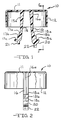
- Fig. 1 is a sectional elevational view of a protective cover for an end yoke in accordance with this invention.
- Fig. 2 is a sectional elevational view, partially broken away, taken along line 2-2 of Fig. 1.
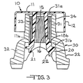
- Fig. 3 is a sectional elevational view of the protective cover illustrated in Fig. 1 mounted on a conventional end yoke.
- the cover 10 includes a generally flat circular end portion 11 having a depending skirt portion 12 formed about the outer periphery thereof.
- the skirt portion 12 is formed integrally with the end portion 11 and extends axially downwardly therefrom to define a hollow cylindrical protected region, as will be explained below.
- First and second legs 15 and 16 are formed integrally with the end portion 11.
- the legs 15 and 16 are located on opposite sides of a central axis passing through the end portion 11 and are equidistantly spaced therefrom. From the end portion 11, the legs 15 and 16 extend downwardly within and beyond the skirt portion 12. As they extend downward, the legs 15 and 16 diverge slightly apart from one another in inverted-V fashion. Thus, the lower ends of the legs 15 and 16 are spaced apart greater than the upper ends. As best shown in Fig. 2, respective strengthening ribs 15a and 16a are formed throughout most of the length of the legs 15 and 16.
- a series of shoulders 17a, 17b, and 17c are formed on an outwardly facing side thereof.
- a similar series of shoulders 18a, 18b, and 18c are formed on an outwardly facing side of the second leg 16 near the lower end thereof.
- the shoulders 17a, 17b, and 17c and the shoulders 18a, 18b, and 18c face in opposite directions.
- the shoulders 17a, 17b, and 17c define increasing axial distances from the end portion 11.
- the shoulders 18a, 18b, and 18c also define increasing axial distances from the end portion 11, which are equal to the respective axial distances defined by the shoulders 17a, 17b, and 17c.
- the transverse distance separating the first shoulders 17a and 18a is less than the transverse distance separating the second shoulders 17b and 18b.
- the transverse distance separating the second shoulders 17b and 18b is less than the transverse distance separating the third shoulders 17c and 18c.
- the second leg 16 is formed somewhat longer than the first leg 15. Below the third shoulder 18c on the second leg 16, a curved surface 20 is formed. The extended length of the second leg 16 and the curved surface 20 are provided to facilitate the installation of the cover 10, as will be described below. Axially extending tabs 21 and 22 are formed on the lower ends of the first and second legs 15 and 16, respectively. The tabs 21 and 22 are provided to facilitate the removal of the cover 10, as will also be described below.
- the entire cover 10 is preferably formed from a relatively stiff, yet slightly flexible material.
- High density polyethylene has been found to function satisfactorily. However, it will be appreciated that other materials may be used to form the cover 10.
- Fig. 3 illustrates the protective cover 10 mounted on an end yoke, illustrated generally at 30.
- the end yoke 30 is conventional in the art and includes a generally cylindrical hub portion 31 having a pair of space apart arms 32 extending therefrom.
- a splined bore 33 is formed through the hub portion 31 extending between two end surfaces 31a and 31b thereof.
- the splined bore 33 permits the end yoke 30 to be mounted on a male splined shaft (not shown) for rotation therewith.
- An outer cylindrical surface 34 of the hub 30 is precisely ground to a smooth finish. This precisely ground outer surface 34 is the portion of the end yoke 30 which must be protected from impacts during shipment.
- the legs 15 and 16 are generally aligned with the splined bore 33 adjacent to the first end 31a of the hub portion 31.
- the inner diameter of the splined bore 33 is slightly smaller than the distance separating the outer sides of the legs 15 and 16. Therefore, the two legs 15 and 16 must be slightly compressed together to permit them to be inserted within the splined bore 33.
- the cover 10 is first slightly angled relative to the end yoke 30. Then, the cover 10 is moved axially such that the longer second leg 16 initially enters the splined bore 33, followed by the first leg 15.
- the legs 15 and 16 may be inserted within the splined bore 33 without exerting a large amount of force to compress them together. Consequently, the amount of force required to begin this installation process is significantly reduced.
- the cover 10 is easily adapted for use with differently sized end yokes 30.
- the axial length of the splined bore 33 will determine which of the shoulder pairs 17a, 18a or 17b, 18b, or 17c, 18c will engage the second end 31b of the hub 31.
- the axial movement of the cover 10 is continued until the appropriate pair of shoulders 17a, 18a or 17b, 18b or 17c, 18c automatically seats against the second end 31b of the hub 31.
- the tabs 21 and 22 are provided to facilitate removal of the cover 10 from the hub 30.
- the tabs 21 and 22 are initially squeezed between the thumb and index finger of an operator. As a result, the legs 15 and 16 are compressed toward one another. This movement disengages the legs from the second end surface 31b of the hub 31, permitting the cover 10 to be moved axially in the opposite direction for removal.
Landscapes
- Engineering & Computer Science (AREA)
- Mechanical Engineering (AREA)
- General Engineering & Computer Science (AREA)
- Sealing Devices (AREA)
- Closures For Containers (AREA)
- Connector Housings Or Holding Contact Members (AREA)
- Telephone Set Structure (AREA)
- Casings For Electric Apparatus (AREA)
- Fluid-Damping Devices (AREA)
Claims (5)
- Schutzdeckel (10), der auf einem hohlen Element (30) befestigbar ist, das eine äußere Oberfläche (34) und eine Öffnung (33) aufweist, und das in einer Stirnfläche (31b) endigt, wobei der Schutzdeckel (10) folgende Teile umfaßt:
Ein Endabschnitt (11), der einen Außenumfang definiert; ein Randabschnitt (12), der vom Außenumfang des Endabschnittes (11) ausgeht;
ein Paar Schenkel (15, 16), die mit dem Endabschnitt (11) verbunden sind und von diesem aus innerhalb des Randabschnittes (12) verlaufen, wobei ferner die Schenkel (15, 16) vom Randabschnitt (12) beabstandet sind, so daß sie einen ringförmigen Zwischenraum mit diesem bilden und die Schenkel (15, 16) sich in die Öffnung (33) des Elementes (30) hineinerstrecken können;
ferner mit Schultern (17, 18), die an wenigstens einem der Schenkel (15, 16) ausgebildet sind, für lösbaren Eingriff mit der Stirnfläche (31b) des Elementes (30), um den Schutzdeckel (10) an diesem zu halten, wobei die äußere Oberfläche (34) des Elementes (30) in dem ringförmigen Zwischenraum zwischen dem Randabschnitt (12) und dem Paar Schenkel (15, 16) aufgenommen ist, so daß sie schützend durch den Randabschnitt (12) abgedeckt ist, dadurch gekennzeichnet, daß eine abwärts gerichtete Nase (21, 22) am äußeren Ende von wenigstens einem der Schenkel (15, 16) ausgebildet ist, um die Abnahme des Schutzdeckels (10) von dem Element (30) zu erleichtern, daß ferner die Nase (21, 22) eine nach außen gerichtete Fläche hat, die, wenn der Schutzdeckel (10) an dem Element (30) befestigt ist, im wesentlichen senkrecht zur Stirnfläche (31b) verläuft. - Schutzdeckel nach Anspruch 1, dadurch gekennzeichnet, daß die Schenkel (15, 16) voneinander divergieren, wenn sie sich von dem Endabschnitt aus erstrecken.
- Schutzdeckel nach Anspruch 1 oder 2, dadurch gekennzeichnet, daß die Schultern erste und zweite Schultern (17a, 17b) umfassen, die an einem der Schenkel (15, 16) ausgebildet ist, und daß die erste Schulter (17a) weiter weg vom Endabschnitt (11) liegt,als die zweite Schulter (17b).
- Schutzdeckel nach Anspruch 1 oder 2, dadurch gekennzeichnet, daß die Schultern erste und zweite Schultern (17a, 17b, 18a, 18b) umfassen, die an jedem der Schenkel ausgebildet sind, und daß die ersten Schultern (17a, 18a) weiter weg vom Endabschnitt (11) liegen, als die zweiten Schultern (17b, 18b).
- Schutzdeckel nach einem der vorhergehenden Ansprüche, dadurch gekennzeichnet, daß wenigstens einer der Schenkel (15, 16) in einer abgerundeten Oberfläche (20) endigt, um den Einbau des Schutzdeckels (10) auf das Element zu erleichtern.
Applications Claiming Priority (2)
| Application Number | Priority Date | Filing Date | Title |
|---|---|---|---|
| US07/441,170 US5048571A (en) | 1989-11-27 | 1989-11-27 | Protective cover for end yoke |
| US441170 | 1989-11-27 |
Publications (2)
| Publication Number | Publication Date |
|---|---|
| EP0430564A1 EP0430564A1 (de) | 1991-06-05 |
| EP0430564B1 true EP0430564B1 (de) | 1994-04-13 |
Family
ID=23751814
Family Applications (1)
| Application Number | Title | Priority Date | Filing Date |
|---|---|---|---|
| EP90312667A Expired - Lifetime EP0430564B1 (de) | 1989-11-27 | 1990-11-21 | Schutzkappe für Gabelkopf |
Country Status (7)
| Country | Link |
|---|---|
| US (1) | US5048571A (de) |
| EP (1) | EP0430564B1 (de) |
| JP (1) | JPH03200548A (de) |
| KR (1) | KR100201577B1 (de) |
| AU (1) | AU632871B2 (de) |
| DE (1) | DE69008124T2 (de) |
| ES (1) | ES2063931T3 (de) |
Families Citing this family (18)
| Publication number | Priority date | Publication date | Assignee | Title |
|---|---|---|---|---|
| US5383494A (en) * | 1993-06-25 | 1995-01-24 | Camco Manufacturing, Inc. | Hose end cap with pivotal lock |
| US5758693A (en) * | 1993-06-25 | 1998-06-02 | Camco Manufacturing, Inc. | Hose end cap with clamp mechanism |
| AUPM911594A0 (en) * | 1994-10-28 | 1994-11-24 | Underwood, Daniel Charles | A protective end cap |
| USD372192S (en) | 1995-04-14 | 1996-07-30 | Nucon Corporation | Cover for a pallet connector |
| US5503189A (en) * | 1995-05-15 | 1996-04-02 | Bunzl Plastics, Inc. | Flange protector having flexible coupling insert and method for detachably coupling same to a conduit |
| US5954094A (en) * | 1997-01-13 | 1999-09-21 | Lufran Incorporated | End cap for providing a fluid-tight seal between dissimilar materials |
| AU5804899A (en) | 1998-10-29 | 2000-05-22 | National Lightning Protection Corporation | A safer lightning rod and warning system |
| JP3419445B2 (ja) * | 1999-09-27 | 2003-06-23 | 株式会社アツミテック | リッド |
| US6532992B1 (en) * | 2000-06-26 | 2003-03-18 | General Electric Co. | Reusable pipe flange cover |
| US6332478B1 (en) | 2000-06-29 | 2001-12-25 | General Electric Company | Reusable pipe flange covers |
| US6475093B1 (en) | 2000-11-29 | 2002-11-05 | Dana Corporation | Protective cover assembly for a slip yoke in a vehicle drive train assembly |
| US6857235B2 (en) | 2001-02-23 | 2005-02-22 | Dayton Superior Corporation | Protective cover for reinforcing bar |
| DE20310502U1 (de) * | 2003-07-09 | 2003-09-18 | Schwarz Verbindungssysteme GmbH, 75382 Althengstett | Schutzkappen-Anordnung für eine aus einem Steck-Bolzen und einer Haltefeder bestehende Verbindungsanordnung für zwei Bauteile |
| US7690505B2 (en) * | 2006-05-30 | 2010-04-06 | Gunite Corporation | Wheel hub shipping retainer system |
| US9546029B1 (en) * | 2015-11-03 | 2017-01-17 | Karl Keevert | Pipe thread protector |
| US10954045B2 (en) * | 2018-06-07 | 2021-03-23 | G&H Diversified Manufacturing Lp | Thread protector for tubular members |
| CN110294209B (zh) * | 2019-04-30 | 2021-05-11 | 武汉船用机械有限责任公司 | 管体零件的焊层防护工装 |
| DE102023102774B4 (de) * | 2023-02-06 | 2024-08-22 | Schaeffler Technologies AG & Co. KG | Verschlusskappe für ein Achsgetriebe sowie Achssystem |
Family Cites Families (17)
| Publication number | Priority date | Publication date | Assignee | Title |
|---|---|---|---|---|
| US622376A (en) * | 1899-04-04 | Albert lieber | ||
| US1749162A (en) * | 1929-03-28 | 1930-03-04 | Henry D Scott | Thread protector |
| US2092535A (en) * | 1936-05-28 | 1937-09-07 | Charles H Schnorr | Thread protector |
| US2195530A (en) * | 1939-06-17 | 1940-04-02 | Frederick F Murphy | Thread protector |
| US2272863A (en) * | 1940-11-04 | 1942-02-10 | Fred M Young | Heat exchange tube protector |
| US2365888A (en) * | 1943-11-18 | 1944-12-26 | Hal R Linderfelt | Tubing closure |
| US3354742A (en) * | 1965-07-12 | 1967-11-28 | Teleflex Inc | Remote control assembly construction |
| US3773169A (en) * | 1970-12-21 | 1973-11-20 | Crawford Fitting Co | Apparatus for use in the make-up of tube fittings |
| US3856050A (en) * | 1972-12-18 | 1974-12-24 | T Rooney | Flange protector |
| US3942681A (en) * | 1973-12-12 | 1976-03-09 | Richardson Ernest T | Flange protector |
| DE2510637C2 (de) * | 1975-03-12 | 1982-11-18 | Hoechst Ag, 6000 Frankfurt | Hohlstab aus gerafftem Schlauch mit den Hohlstab umgebender Hülle |
| US4014368A (en) * | 1976-02-13 | 1977-03-29 | Alliance Plastics, Inc. | Flange protector |
| US4202378A (en) * | 1976-06-11 | 1980-05-13 | Bush Lyman F | Rebar safety cap |
| DE7912106U1 (de) * | 1979-04-26 | 1979-08-02 | Em Tech Gmbh | Schutzkappe fuer Flanscharmaturen |
| US4423753A (en) * | 1982-08-16 | 1984-01-03 | Smith John S | Flange protector |
| US4518017A (en) * | 1983-12-16 | 1985-05-21 | Dana Corporation | Protective cover assembly |
| US4694863A (en) * | 1986-01-15 | 1987-09-22 | Cajon Company | Protective cap |
-
1989
- 1989-11-27 US US07/441,170 patent/US5048571A/en not_active Expired - Lifetime
-
1990
- 1990-11-21 ES ES90312667T patent/ES2063931T3/es not_active Expired - Lifetime
- 1990-11-21 DE DE69008124T patent/DE69008124T2/de not_active Expired - Fee Related
- 1990-11-21 EP EP90312667A patent/EP0430564B1/de not_active Expired - Lifetime
- 1990-11-26 KR KR1019900019196A patent/KR100201577B1/ko not_active Expired - Fee Related
- 1990-11-26 JP JP2318158A patent/JPH03200548A/ja active Pending
- 1990-11-26 AU AU66984/90A patent/AU632871B2/en not_active Ceased
Also Published As
| Publication number | Publication date |
|---|---|
| KR100201577B1 (ko) | 1999-06-15 |
| DE69008124D1 (de) | 1994-05-19 |
| AU6698490A (en) | 1991-05-30 |
| KR910010085A (ko) | 1991-06-28 |
| DE69008124T2 (de) | 1994-07-21 |
| EP0430564A1 (de) | 1991-06-05 |
| AU632871B2 (en) | 1993-01-14 |
| JPH03200548A (ja) | 1991-09-02 |
| ES2063931T3 (es) | 1995-01-16 |
| US5048571A (en) | 1991-09-17 |
Similar Documents
| Publication | Publication Date | Title |
|---|---|---|
| EP0430564B1 (de) | Schutzkappe für Gabelkopf | |
| US4687392A (en) | Torque limiting fastener | |
| SE419793B (sv) | Anordning for lasning av ror- och slangkopplingar | |
| US3995897A (en) | Coupling | |
| US4472095A (en) | Locking fastener | |
| US4791826A (en) | Gearshift knob joining arrangement | |
| US3785584A (en) | Snap lock assembly | |
| GB2070737A (en) | Drive coupling | |
| US4684157A (en) | Hose coupling | |
| US4692079A (en) | Bowed internal spring retaining ring that functions regardless of its orientation when installed in a groove | |
| US5078533A (en) | Driveline yoke with improved seal retainer | |
| US4274460A (en) | Panel fastener joint | |
| US4074945A (en) | Cable fastener assembly | |
| EP0153487A1 (de) | Bedeckung | |
| EP0100577A1 (de) | Muffenhalterung | |
| EP0154216B1 (de) | Verfahren zur Herstellung einer Schutzvorrichtung für eine Kardanwelle und durch dieses Verfahren hergestellte Schutzvorrichtung | |
| US5674079A (en) | Ground lug | |
| SE445408B (sv) | Kabelgenomforing | |
| EP1503115B1 (de) | Befestigung für einen Faltenbalg. | |
| GB2045884A (en) | Safety guards for cardan shafts | |
| US5076406A (en) | Radially interlocking clutch brake | |
| JP4039690B2 (ja) | ろう接材料スリーブ及びその形成方法 | |
| EP0771251B1 (de) | Zange | |
| US4290711A (en) | Key system for shaft and gear or the like | |
| EP0128039B1 (de) | Tragbare Werkzeuge und ihre Handgriffe |
Legal Events
| Date | Code | Title | Description |
|---|---|---|---|
| PUAI | Public reference made under article 153(3) epc to a published international application that has entered the european phase |
Free format text: ORIGINAL CODE: 0009012 |
|
| AK | Designated contracting states |
Kind code of ref document: A1 Designated state(s): DE ES FR GB |
|
| 17P | Request for examination filed |
Effective date: 19911127 |
|
| 17Q | First examination report despatched |
Effective date: 19921016 |
|
| GRAA | (expected) grant |
Free format text: ORIGINAL CODE: 0009210 |
|
| AK | Designated contracting states |
Kind code of ref document: B1 Designated state(s): DE ES FR GB |
|
| REF | Corresponds to: |
Ref document number: 69008124 Country of ref document: DE Date of ref document: 19940519 |
|
| ET | Fr: translation filed | ||
| REG | Reference to a national code |
Ref country code: ES Ref legal event code: FG2A Ref document number: 2063931 Country of ref document: ES Kind code of ref document: T3 |
|
| PLBE | No opposition filed within time limit |
Free format text: ORIGINAL CODE: 0009261 |
|
| STAA | Information on the status of an ep patent application or granted ep patent |
Free format text: STATUS: NO OPPOSITION FILED WITHIN TIME LIMIT |
|
| 26N | No opposition filed | ||
| REG | Reference to a national code |
Ref country code: GB Ref legal event code: IF02 |
|
| PGFP | Annual fee paid to national office [announced via postgrant information from national office to epo] |
Ref country code: GB Payment date: 20041117 Year of fee payment: 15 |
|
| PGFP | Annual fee paid to national office [announced via postgrant information from national office to epo] |
Ref country code: FR Payment date: 20041119 Year of fee payment: 15 |
|
| PGFP | Annual fee paid to national office [announced via postgrant information from national office to epo] |
Ref country code: ES Payment date: 20041209 Year of fee payment: 15 |
|
| PGFP | Annual fee paid to national office [announced via postgrant information from national office to epo] |
Ref country code: DE Payment date: 20041230 Year of fee payment: 15 |
|
| PG25 | Lapsed in a contracting state [announced via postgrant information from national office to epo] |
Ref country code: GB Free format text: LAPSE BECAUSE OF NON-PAYMENT OF DUE FEES Effective date: 20051121 |
|
| PG25 | Lapsed in a contracting state [announced via postgrant information from national office to epo] |
Ref country code: ES Free format text: LAPSE BECAUSE OF NON-PAYMENT OF DUE FEES Effective date: 20051122 |
|
| PG25 | Lapsed in a contracting state [announced via postgrant information from national office to epo] |
Ref country code: DE Free format text: LAPSE BECAUSE OF NON-PAYMENT OF DUE FEES Effective date: 20060601 |
|
| GBPC | Gb: european patent ceased through non-payment of renewal fee |
Effective date: 20051121 |
|
| PG25 | Lapsed in a contracting state [announced via postgrant information from national office to epo] |
Ref country code: FR Free format text: LAPSE BECAUSE OF NON-PAYMENT OF DUE FEES Effective date: 20060731 |
|
| REG | Reference to a national code |
Ref country code: FR Ref legal event code: ST Effective date: 20060731 |
|
| REG | Reference to a national code |
Ref country code: ES Ref legal event code: FD2A Effective date: 20051122 |