EP0430630A2 - Elektrophotographischer Photorezeptor und Bildherstellungsverfahren - Google Patents
Elektrophotographischer Photorezeptor und Bildherstellungsverfahren Download PDFInfo
- Publication number
- EP0430630A2 EP0430630A2 EP90312847A EP90312847A EP0430630A2 EP 0430630 A2 EP0430630 A2 EP 0430630A2 EP 90312847 A EP90312847 A EP 90312847A EP 90312847 A EP90312847 A EP 90312847A EP 0430630 A2 EP0430630 A2 EP 0430630A2
- Authority
- EP
- European Patent Office
- Prior art keywords
- photoreceptor
- image
- phthalocyanine pigment
- photoreceptor according
- toner
- Prior art date
- Legal status (The legal status is an assumption and is not a legal conclusion. Google has not performed a legal analysis and makes no representation as to the accuracy of the status listed.)
- Withdrawn
Links
Images




Classifications
-
- G—PHYSICS
- G03—PHOTOGRAPHY; CINEMATOGRAPHY; ANALOGOUS TECHNIQUES USING WAVES OTHER THAN OPTICAL WAVES; ELECTROGRAPHY; HOLOGRAPHY
- G03G—ELECTROGRAPHY; ELECTROPHOTOGRAPHY; MAGNETOGRAPHY
- G03G5/00—Recording-members for original recording by exposure, e.g. to light, to heat or to electrons; Manufacture thereof; Selection of materials therefor
- G03G5/02—Charge-receiving layers
- G03G5/04—Photoconductive layers; Charge-generation layers or charge-transporting layers; Additives therefor; Binders therefor
- G03G5/06—Photoconductive layers; Charge-generation layers or charge-transporting layers; Additives therefor; Binders therefor characterised by the photoconductive material being organic
- G03G5/0664—Dyes
- G03G5/0696—Phthalocyanines
Definitions
- the present invention relates to an electrophotographic photoreceptor, more specifically to an electrophotographic photoreceptor using a specific phthalocyanine dye as a photoconductive material, useful to a printer and a copying machine, and suitable for forming latent images with a semiconductor laser ray or an LED ray.
- organic photoconductive materials have come to be widely used instead of inorganic ones for the electrophotographic photoreceptors, because a wider freedom for selection of the raw materials for the organic photoconductive materials and a variety of the combinations of the raw materials and the synthesis conditions make it possible to obtain the various types of the organic photoconductive materials, which in turn makes it easy to prepare a desired photoreceptor for a specific purpose.
- a function separation type photoreceptor comprising an organic photoconductive material, in which there are provided a carrier generation layer and a carrier transfer layer both containing the different materials responsible for the respective functions, can have the further wider freedom of material selection and thereby an improvement in the electrophotographic properties such as electrification ability, sensitivity and durability can be expected.
- a more improvement in image quality and an image edition function are demanded to a copying machine.
- development of a digital control copying machine or printer is under way, and improvement of a photoreceptor therefore is strongly desired.
- dotted latent images are formed by a dotwise exposure with a laser ray modulated by an image signal, and then the latent images are developed by a reverse developing method to form images, wherein a semiconductor laser capable of providing a simpler, smaller and less expensive exposing unit is preferred. Its oscillation wavelength is in an infrared region of more than 750 nm. Therefore, a photoreceptor applied thereto is required to have a high sensitivity at least in a wavelength region of 750 to 850 nm.
- organic dyes and pigments are proposed as a carrier generating substance for the foregoing function separation type photoreceptor, and there are used practically polycyclic quinone pigments such as dibromoanthanthrone, pyrylium dyes and eutectic complexes thereof with polycarbonate, squarium pigments, phthalocyanine pigments and azo pigments.
- polycyclic quinone pigments such as dibromoanthanthrone, pyrylium dyes and eutectic complexes thereof with polycarbonate, squarium pigments, phthalocyanine pigments and azo pigments.
- phthalocyanine dyes are regarded to be the most fitted for an electrophotographic photoreceptor packaged with a light source of a semiconductor laser ray because of their higher quantum efficiency in photoelectric transfer and high spectral sensitivity extended to a near infrared region.
- phthalocyanine has a crystal form of ⁇ , ⁇ , ⁇ , X and Y types and that the characteristics of the photoreceptor are affected notably by the crystal form thereof, and phthalocyanine of a crystal form capable of providing stably a high sensitivity and an excellent electrification property is required.
- titanylphthalocyanines having a high sensitivity and a good stability in a repetitive operation under high temperature, high humidity and high ozone conditions; ⁇ -type titanylphthalocyanine has high sensitivity but poor stability; ⁇ -type titanylphthalocyanine has poor sensitivity; and Y-type phthalocyanine disclosed in Japanese Patent Publication Open to Public Inspection has a deteriorated charging property in repeated use in a high ozone condition.
- a contact developing method and a non-contact developing method are conventionally used in forming an image with an electrophotographic photoreceptor.
- the non-contact developing method particularly the jumping developing method, is liable to be affected by environmental conditions. Particularly, repeated use of a photoreceptor under high temperature humidity conditions and lowering of electrification properties of corona electrodes owing to scattering of toners in a repetitive operation cause deterioration of image quality such as lowering of resolution and increase of fogging.
- An object of the present invention is to provide an electrophotographic photoreceptor containing a specific phthalocyanine pigment and having excellent repeating properties and high sensitivity with less liability to be affected by environmental conditions.
- Another object of the present invention is to provide a method of forming images with the above photoreceptor.
- an electrophotographic photoreceptor comprising a conductive substrate and provided thereon a photoreceptive layer containing a phthalocyanine pigment and a binder resin, wherein the phthalocyanine pigment has a water molecule the most of the substances absorbed thereon, provided that the contents of the adsorbed substances are measured by a vacuum method.
- Figs. 1 through 6 are cross-sectional drawings of the layer configuration of the photoreceptor according to the invention.
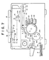
- Fig. 7 shows a schematic cross-sectional drawing of an image forming equipment using the photoreceptor of the invention.
- Fig. 8 is a block diagram of copying operations of the equipment shown in Fig. 7.
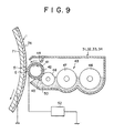
- Fig. 9 is a cross-sectional drawing of the principal part of a developing device.
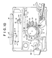
- Fig. 10 shows a schematic cross-sectional drawing of a color copying machine.
- Figs. 11 to 13 show the differential thermal curves of phthalocyanines of the invention.
- Fig. 14 shows a differential thermal curve of Y-type phthalocyanine and
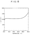
- Fig. 15 shows a differential thermal curve of ⁇ -type titanylphthalocyanine.
- the phthalocyanine pigments of the invention have different crystal aggregation conditions from those of the titanylphthalocyanine pigments disclosed in the foregoing patent publications and are characterized by that they contain water molecules the most by number of the substances adsorbed thereon, of which contents are measured by a vacuum method, and that they have an aggregation condition in which their absorption spectra in the visible and near infrared regions have the maximum absorptions in 780 to 860 nm. They have a high sensitivity to a semiconductor laser ray.
- the adsorbed substances are analyzed in the following manner:
- a 3.0 cm3 glass ampul in which 0.5 g of a phthalocyanine pigment is sealded at an atmospheric pressure and 60% RH, and then the ampul is broken under a vacuum of 2 ⁇ 10 ⁇ 8 Torr to measure the molecular numbers of the substances desorbed from the phthalocyanine pigment by analyzing with a quadrupole mass spectrometer.
- the phthalocyanine pigment of the invention adsorbs water the most of hydrogen, nitrogen, carbon dioxide and water while a conventional phthalocyanine pigment adsorbs nitrogen the most.
- the phthalocyanine pigment of the invention has an endothermic peak between 80°C and 120°C in a differential thermal analysis.
- phthalocyanine pigments examples include non-metallic phthalocyanines, titanylphthalocyanines, vanadylphthalocyanines, lead phthalocyanines, chloroindium phthalocyanines and tin phthalocyanines. Of them, titanylphthalocyanine pigments and vanadylphthalocyanine pigments are preferred. Particularly preferred is a titanylphthalocyanine pigment of which X-ray diffraction spectrum with a Cu-K ⁇ ray has the peaks at Bragg angles (2 ⁇ ) of 9.5° ⁇ 0.2° and 27.2° ⁇ 0.2°.
- the basic structure of the titanylphthalocyanine pigment used in the invention is represented by the following formula: wherein X1, X2, X3 and X4 independently represent a hydrogen atom, a halogen atom, an alkyl group and an alkoxy group; and n, m, l and k independently represent an integer of 0 to 4.
- Titanium tetrapropoxide is added to the mixture of 1,3-diimino-isoindoline and sulfolane to react in a nitrogen atmosphere at 80 to 300°C, preferably 100 to 260°C. After completion of the reaction, the mixture is allowed to cool, and then precipitated titanylphthalocyanine is filtered. Subsequently, the product is subjected to mixed solvent treatment to obtain the phthalocyanine pigment of the invention.
- a mixed solvent comprising hydrophilic solvents such as alcohol and ketone.
- a homomixer, a disperser, an agitator, a ball mill, a sand mill or an attritor can be used as well as a conventional stirrer.
- a carrier generation substance other than the phthalocyanine pigment of the invention may be jointly used, examples of which are ⁇ -type, mixture of ⁇ - and ⁇ -types, ⁇ -type and amorphous titanylphthalocyanines having different crystal forms from that of the phthalocyanine pigment of the invention; azo pigments; anthraquinone pigments; perylene pigments; polycyclic quinone pigments; and squarium pigments.
- the photoreceptor of the invention can be prepared by dispersing the phthalocyanine pigment of the invention in a solution dissolving a binder resin in a solvent, dissolving therein a carrier transfer substance to prepare a coating solution and coating it on a conductive support, which may have thereon a subbing layer, by methods such as dip coating, spray coating and spiral coating.
- the photoreceptor prepared as above has a single-layered configuration shown in Fig. 1 or Fig. 2.
- Function separation type photoreceptors shown in Figs. 3 through 6 are preferred to provide high sensitivity and durability, wherein a coating solution containing a binder resing and the pigment is coated on a conductive support 1 to form a carrier generation layer 2; then, a coating solution containing a carrier transfer substance is coated on the carrier generation layer 2 to form a carrier transfer layer 3, whereby a photoreceptive layer of double-layered configuration 4 (Fig. 3 or 5) or 4′ (Fig. 4 or 6) is formed.
- the carrier generation layer 2 and the carrier transfer layer 3 can be provided by dissolving or dispersing each of the carrier generation and transfer substances together with a binder resin in a solvent or dispersant coating the solutions or dispersions on a support, respectively.
- the binder used for the photoreceptive layer is preferably a hydrophobic polymer capable of forming an insulated film with a high dielectric constant. Examples of such a polymer are as follows:
- binder resins may be used singly or in combination.
- the addition rate of the carrier generation substance to the binder resin is preferably 10 to 600 wt%, more preferably 50 to 400 wt%.
- the thickness of the carrier generation layer is preferably 0.01 to 20 ⁇ m, more preferably 0.05 to 5 ⁇ m.
- the carrier generation substance is preferably a fine powder having an average particle size of 2 ⁇ m or less, preferably 1 ⁇ m or less. Too large particle size is liable to hinder particles from dispersing in the layer and form protrusions of particle on the surface to thereby deteriorate surface smoothness. In some cases, the protrusions cause electric discharge or adsorption of toner particles, which tends to form toner filming.
- the examples of the carrier transfer substance are the compounds having a nitrogen-containing heterocyclic ring or a ring condensed therewith, such as oxazoles, oxadiazoles, thiazoles, thiadiazoles and imidazoles; polyarylalkane compounds; pyrazoline compounds; hydrazone compounds, triarylamine compounds; styryl compounds; styryltriphenylamine compounds; ⁇ -phenylstyryltriphenylamine compounds, butadiene compounds, hexatriene compounds, carbazole compounds; and condensed polycyclic compounds.
- carrier transfer substances are used preferably in an amount of 10 to 500% by weight of the binder resin.
- the thickness of the carrier transfer layer is 1 to 100 ⁇ m, preferably 5 to 30 ⁇ m.
- the photoreceptive layer on the photoreceptor of the invention may contain an electron acceptable substance so that sensitivity enhancement, minimization of residual voltage and lowering of fatigue in a repetitive operation can be expected.
- the electron acceptable substance are succinic anhydride, maleic anhydride, dibromosuccinic anhydride, phthalic anhydride, tetrachlorophthalic anhydride, tetrabromophthalic anhydride, 3-nitrophthalic anhydride, 4-nitrophthalic anhydride, pyromellitic anhydride, mellitic anhydride, tetracyanoethylene, tetracyanoquinodimethane, o-dinitrobenzene, m-dinitrobenzene, 1,3,5-trinitrobenzene, p-nitrobenzonitrile, picryl chloride, quinonechloroimide, chloranil, bromal, dichlorodicyano-p-benzoquinone, anthraquinone, dinitroanthraquino
- the photoreceptive layer may contain a deterioration inhibitor such as an antioxidant and an optical stabilizer in order to improve preservability and durability.
- the conductive support used in the invention may be a metal plate, metal drum, and a paper or plastic film having conductivity which is provided by coating, vapor-depositing or laminating thereon a thin film of a conductive compound such as a conductive polymer, indium oxide and metal such as aluminum and palladium.
- a conductive compound such as a conductive polymer, indium oxide and metal such as aluminum and palladium.
- the intermediate layer 5 which functions as an adhesive layer or a barrier layer, there can be used the high polymers described above as the binder resins, an organic polymer such as polyvinyl alcohol, ethyl cellulose, carboxymethylcellulose and polyamide, and aluminum oxide.
- an organic polymer such as polyvinyl alcohol, ethyl cellulose, carboxymethylcellulose and polyamide, and aluminum oxide.
- Fig. 7 is a schematic cross-sectional drawing of a copying machine.
- an image reading section LE an original copy 18 placed on an original copy stand 19 is exposed to a light source 13 movable in an X direction, and a reflected light 20 is imaged on each of CCD image pick-up elements 17R, 17G and 17B for red, green and blue colors, respectively, through a mirror 14, a lens 15 and a color separation filter 16.
- CCD image pick-up elements convert optical information to time series electric signals and send them to an image data processing section TR1 (see Fig. 8), where record image data are formed.
- a modulator MD modulates a laser ray from a semiconductor laser 21 in accordance with record image data from a video signal processing section TR2 (22 Fig. 7 is a polygonal mirror). Meanwhile, the surface of an image carrier 1 (photoreceptor drum) is uniformly electrified by a scorotron electrification electrode 2. Subsequently, a modulated laser ray L from the laser optical system 10 is radiated on the image carrier 1, whereby an electrostatic latent image is formed. An electrostatic latent image formed through a blue color separation filter is subjected to reversal development by a yellow toner contained in a developing device 31.
- the image carrier 1 on which a toner image is formed is uniformly electrified once again by the scorotron electrification electrode 2. Similarly, the magenta and cyan toner images are formed on the image carrier.
- a recording paper P is fed to a drum-type transfer unit 63 through a feed roller 23 and gripped by a gripper 64 to be sent in a direction of an arrow with a rotation of the drum.
- the developed toner image is then transferred onto the recording paper P with a transferring device 5 equipped in the transfer unit 63.
- the recording paper P is immediately separated from the transfer unit 63 with a separation nail 66 and then sent to a heat-fixing roller 9 for fixing the toner image.
- the separation nail 66 does not work immediately, and the recording paper P rotates while being fixed on the transfer unit 63.
- a transfer-accelerating exposure may be performed before transferring by the transferring device 5.
- Residual toners on the surface of the image carrier 1 after transferring of a toner image of one color are removed by a cleaning device 8 (de-electrification may be carried out before cleaning, if necessary) in preparation for the following image forming procedure. Then, the above procedure is repeated to transfer, a toner image of the other colors over a preceding toner image fixed on the recording paper P held on the transfer unit 63. The above procedures are repeated to form a multi-colored image on the recording paper P, which is separated from the transfer unit 63 with the separation nail 66, followed by fixing similarly to the case of the monochromatic image.
- Fig. 8 is a block diagram of copying operations of the copying machine shown in Fig. 7.
- an operation section OP actuates a control section CT, by which an image reading section LE is controlled to convert optical informations of the original copy to time series signals of respective colors.
- the data converted to the signals are processed in an image data processing section TR1 and then converted to the data suitable for recording at an video signal processing section TR2.
- the image forming section RE performs the above image forming procedure to transfer a toner image on a copying paper and form a copied image.
- An electrophotography is used in the image forming section RE.
- an image memory ME such as a ROM (read only memory), a floppy disk and a magnetic tape, and can be taken out to send to the image forming section RE.
- Fig. 9 is an enlarged figure of the developing devices 31 to 34, wherein a non-magnetic developing sleeve 41 which serves as a developer carrier rotates left while an internal magnet 42 rotates right, whereby a developer 50 in a developer reservoir 43 is adsorbed on the surface of the developing sleeve 41 and carried in a direction reverse to that of the rotation of a magnet 42.
- the developer carried on the developing sleeve 41 is regulated to a proper thickness in transit by a layer thickness regulating blade 44 to form a developer layer.
- a DC bias voltage and/or an AC voltage are applied to the developing sleeve 41 by a bias power source 52 for developing in a developing area E.
- the developer layer passed through the developing area E is removed from the developing sleeve 41 by a cleaning blade 45 and returned to the developer reservoir 43.
- the toner is fed from a toner hopper to the developer reservoir 43 by a toner feeding roller, both of which are not illustrated.
- the developer 50 is stirred uniformly by stirring/carrying means 46, 47 and 48, and fully charged.
- the developer layer may be carried with the developing sleeve 41 resting or rotating right, or with the magnet 42 resting or rotating left.
- the developer 50 may be a one-component developer comprising magnetic toner particles but a two-components developer comprising magnetic carrier particles and non-magnetic toner particles is preferred in view of color sharpness and easiness in controlling electrification of toner particles.
- Developing with the developing device of Fig. 9 is carried out by the non-contact developing method.
- Specific conditions of the development may be the same as those described in Japanese Patent O.P.I. Publication Nos. 147652/1982 or 181362/1984, both of which use two-component developers.
- the conditions may be the same as those described in Japanese Patent O.P.I. Publication No. 18656/1980 or Japanese Patent Examined Publication No. 9475/1966.
- an alternating electric field applied between the image carrier 1 and the developing sleeve 41 be 100 Hz to 5 KHz and that the DC bias voltage applied to the developing sleeve 41 be 100 V to 2 KV.
- An opening 51 between the image carrier 1 and the developing sleeve 41 is controlled to the range of 10 to 2000 ⁇ m. Therefore, it is preferred that the thickness of the developer layer regulated by the layer thickness regulating blade 44 be thinner than the above opening.
- the particle sizes of a carrier and a toner are preferably 5 to 100 ⁇ m and 20 ⁇ m or less, respectively.
- Useful carriers are a magnetic carrier and an insulating carrier coated with an insulating substance.
- a conventional insulating toner can be used.
- FIG. 10 an image forming equipment capable of forming multi-colored images in one cycle of transfer process is explained in accordance with Fig. 10, in which a multi-color image forming equipment of a digital copying system is shown.
- a four-colors toner image is formed on the image carrier 1 by repeating the procedures described in the above equipment.
- the four-colors toner image may be electrified with an electrification electrode in advance of transfer. Then, it is transferred on the recording paper P by a transfer electrode 4, which is separated from the image carrier 1 by a separation electrode 5 and subjected to fixing by a fixing device 6.
- the image carrier 1 is cleaned by a cleaning device 8.
- Synthesis 1 was repeated to obtain the crystals having the peaks at the Bragg angles (2 ⁇ ) of 9.5° ⁇ 0.2° and 27.2° ⁇ 0.2° in an X-ray diffraction spectrum, except that methanol used for treating the wet paste in the mixed solvent was replaced with acetone.
- a differential thermal analysis of this crystal gave a differential thermal curve shown in Fig. 8.
- the ground product taken out from the grinder was washed with water and methanol to remove the pulverizing aid and dispersant. Then, the product was refined with a 2% dilute sulfuric acid aqueous solution and filtered, followed by washing and drying, to obtain the crystals having the peaks at the Bragg angles of 9.5 ⁇ 0.2° and 27.2 ⁇ 0.2° in an X-ray diffraction spectrum.
- the differential thermal curve is shown in Fig. 14.
- Synthesis 1 was repeated to obtain ⁇ -titanylphthalocyanine, except that the wet paste was stirred and heated in ⁇ -chloronaphthalene.
- An X-ray diffraction spectrum of the product had the peaks at the Bragg angles (2 ⁇ ) of 9.3° ⁇ 0.2°, 10.6° ⁇ 0.2, 13.2° ⁇ 0.2°, 15.1° ⁇ 0.2°, 15.7° ⁇ 0.2°, 16.1° ⁇ 0.2, 20.8° ⁇ 0.2°, 23.3° ⁇ 0.2°, 26.3° ⁇ 0.2° and 27.1° ⁇ 0.2°.
- the differential thermal curve thereof is shown in Fig. 15.
- titanylphthalocyanines and vanadylphthalocyanine prepared in Syntheses 1 to 3 contain water molecules at the largest percentage.
- part means part by weight
- a copolymer polyamide (Luckamide 5003 made by Dainippon Ink & Chemicals, Inc.) was dissolved in 100 parts of methanol by heating.
- the solution was filtered with a 0.6 ⁇ m filter and coated on an aluminum drum by the penetration coating method to form a subbing layer of 0.5 ⁇ m thickness.
- a dispersion was prepared by dispersing 3 parts of the inventive titanylphthalocyanine pigment prepared in Synthesis 1, 3 parts of a cellulose-modified silicone resin (KR 5240 made by Shin-Etsu Chemical Co.) as a binder resin, and 100 parts of methyl isobutyl ketone as a dispersant with a sand mill. Then, the dispersion was coated on the subbing layer by the penetration coating method to form a carrier generating layer of 0.2 ⁇ m thickness.
- a cellulose-modified silicone resin KR 5240 made by Shin-Etsu Chemical Co.
- a photoreceptor sample was prepared in the same manner as in Example 1, except that the titanylphthalocyanine pigment prepared in Synthesis 1 was replaced with what was prepared in Synthesis 2.
- a photoreceptor sample was prepared in the same manner as in Example 1, except that the titanylphthalocyanine pigment of Synthesis 1 was replaced with the vanadylphthalocyanine pigment prepared in Synthesis 3.
- copolymer polyamide CM 8000 made by Toray was dissolved in 100 parts of methanol by heating. The solution was filtered with a 0.6 ⁇ m filter and coated on an aluminum drum by the penetration coating method to form a subbing layer of 0.5 ⁇ m thickness.
- the dispersion was prepared by dispersing 3 parts of the inventive titanylphthalocyanine pigment prepared in Synthesis 1, 3 parts of a polyvinylbutyral resin Eslec BHS made by Sekisui Chemical and 100 parts of methyl isobutyl ketone with a sand mill.
- the dispersion was coated on the subbing layer by the penetration method to form a carrier generating layer of 0.2 ⁇ m thickness, and a carrier transport layer was provided thereon in the same manner as in Example 1, whereby the photoreceptor sample of the invention was prepared.
- Example 4 was repeated to prepare the photoreceptor sample of the invention, except that the titanylphthalocyanine pigment prepared in Synthesis 1 was replaced with what was prepared in Synthesis 2.
- Example 4 was repeated to prepare the photoreceptor sample of the invention, except that the titanylphthalocyanine pigment prepared in Synthesis 1 was replaced with the vanadylphthalocyanine pigment prepared in Synthesis 3.
- Example 1 was repeated to prepare the photoreceptor sample of the comparison, except that the titanylphthalocyanine pigment prepared in Synthesis 1 was replaced with what was prepared in Comparative Synthesis 1.
- Example 1 was repeated to prepare the photoreceptor sample of the comparison, except that the titanylphthalocyanine pigment prepared in Synthesis 1 was replaced with what was prepared in Comparative Synthesis 2.
- Example 4 was repeated to prepare the photoreceptor sample of the comparison, except that the titanylphthalocyanine pigment prepared in Synthesis 1 was replaced with what was prepared in Comparative Synthesis 1.
- Example 4 was repeated to prepare the photoreceptor sample of the comparison, except that the titanylphthalocyanine pigment prepared in Synthesis 1 was replaced with what was prepared in Comparative Synthesis 2.
- Each of the inventive and comparative samples was mounted in a modified model of U-Bix 1550 made by Konica Corp. (having a semiconductor laser light source). After adjusting in a grid voltage V G to 600 [V], a potential V H of an unexposed portion and a potential V L of an exposed portion illuminated at 0.7 mW were measured. Further, V H and V L were also measured on the samples which were subjected to 50,000 cycles of copying operations at 33°C and 80%RH. The results are shown in Table 1.
- the inventive photoreceptors have the high sensitivities and excellent stability in a repetitive use at a high temperature, high humidity and high ozone concentration, while the sensitivities of the comparative photoreceptors are deteriorated in a repetitive use at the above environment.
- An aluminum drum coated with a polyamide resin layer of 0.3 ⁇ m thickness was coated by the dip coating method with a dispersion prepared by dispersing 3 parts of the titanylphthalocyanine pigment prepared in Synthesis 1 and 35 parts of a silicone resin (15% xylene-butanol solution of KR-5240 made by Shin-Etsu Chemical Co.) in 100 parts of methyl ethyl ketone with a sand mill to form a carrier generating layer of 0.2 ⁇ m thickness.
- the drum was coated by the blade coating method with a solution prepared by dissolving 1 part of the foregoing carrier transfer substance T-1, 1.3 parts of a polycarbonate resin (Iupilon Z200 made by Mithubishi Gas Chemical Co.), and a small amount of a silicone oil (KF-54 made by Shin-Etsu Chemical Co.) in 10 parts of 1,2-dichloroethane to form a carrier transfer layer of 20 ⁇ m thickness, whereby the photoreceptor sample of the invention was prepared.
- a solution prepared by dissolving 1 part of the foregoing carrier transfer substance T-1 1.3 parts of a polycarbonate resin (Iupilon Z200 made by Mithubishi Gas Chemical Co.), and a small amount of a silicone oil (KF-54 made by Shin-Etsu Chemical Co.) in 10 parts of 1,2-dichloroethane to form a carrier transfer layer of 20 ⁇ m thickness, whereby the photoreceptor sample of the invention was prepared.
- a polycarbonate resin I
- the sample was mounted in a modified model of a color copier DC-8010 (made by Konica Corp.; two-component developer type) equipped with a 400 dpi optical system, and quality of copied images was evaluated, wherein a latent image was developed by the non-contact jumping method of a reversal system.
- the developing conditions are described below.
- the resolution and background fog were evaluated for the image quality of the sample at an initial stage and after 50,000 cycles of a copying operation at 33°C and 80% RH. The results are shown in Table 2.
- a comparative photoreceptor sample was prepared and evaluated in the same manners as in Example 7, except that the titanylphthalocyanine pigment prepared in Comparative Synthesis 1 was used instead of the titanylphthalocyanine pigment of Synthesis 1.
- a comparative photoreceptor sample was prepared and evaluated in the same manners as in Example 7, provided that a developer layer was contacted to the photoreceptor.
- the results are shown in Table 2.
- the developing conditions were as follows:
- non-contact developing with the phthalocyanine photoreceptor of the invention makes it passible to provide a high resolution without causing background fog even after repeating 50,000 cycles of copying operation at such a high temperature and humidity as 33°C and 80% RH.
- the photoreceptor sample of the invention was prepared in the same manner as in Example 7.
- the sample was mounted in an image forming equipment shown in Fig. 10, and quality of copied images was evaluated.
- a comparative photoreceptor sample was prepared in the same manner as in Example 7, except that the titanylphthalocyanine pigment of Comparative Synthesis 1 was used instead of the titanylphthalocyanine pigment of Synthesis 1.
- the photoreceptor of the invention has little degradation of a surface potential and causes substantially no fog, optical memory and ghost.
Landscapes
- Physics & Mathematics (AREA)
- General Physics & Mathematics (AREA)
- Photoreceptors In Electrophotography (AREA)
Applications Claiming Priority (6)
| Application Number | Priority Date | Filing Date | Title |
|---|---|---|---|
| JP30871689A JPH03168645A (ja) | 1989-11-28 | 1989-11-28 | 電子写真感光体 |
| JP308716/89 | 1989-11-28 | ||
| JP2034360A JP2838429B2 (ja) | 1990-02-15 | 1990-02-15 | 画像形成方法 |
| JP2034359A JPH03237465A (ja) | 1990-02-15 | 1990-02-15 | 画像形成方法 |
| JP34359/90 | 1990-02-15 | ||
| JP34360/90 | 1990-02-15 |
Publications (2)
| Publication Number | Publication Date |
|---|---|
| EP0430630A2 true EP0430630A2 (de) | 1991-06-05 |
| EP0430630A3 EP0430630A3 (en) | 1991-07-10 |
Family
ID=27288398
Family Applications (1)
| Application Number | Title | Priority Date | Filing Date |
|---|---|---|---|
| EP19900312847 Withdrawn EP0430630A3 (en) | 1989-11-28 | 1990-11-27 | Electrophotographic photoreceptor and method of forming images |
Country Status (1)
| Country | Link |
|---|---|
| EP (1) | EP0430630A3 (de) |
Cited By (3)
| Publication number | Priority date | Publication date | Assignee | Title |
|---|---|---|---|---|
| EP0584698A3 (de) * | 1992-08-24 | 1994-10-12 | Xerox Corp | Photogenerierende Pigmente und Verfahren zu ihrer Herstellung. |
| EP0801330A1 (de) * | 1996-04-10 | 1997-10-15 | Mitsubishi Chemical Corporation | Electrophotographischer Photorezeptor |
| US5968696A (en) * | 1997-04-11 | 1999-10-19 | Fit Corporation | Electrophotographic photoreceptor |
Family Cites Families (2)
| Publication number | Priority date | Publication date | Assignee | Title |
|---|---|---|---|---|
| CA1279787C (en) * | 1985-12-06 | 1991-02-05 | Tatsuro Iwabuchi | Electrophotographic photoconductor using phthalocyanine compound |
| JPS644747A (en) * | 1987-06-26 | 1989-01-09 | Minolta Camera Kk | Photosensitive body |
-
1990
- 1990-11-27 EP EP19900312847 patent/EP0430630A3/en not_active Withdrawn
Cited By (5)
| Publication number | Priority date | Publication date | Assignee | Title |
|---|---|---|---|---|
| EP0584698A3 (de) * | 1992-08-24 | 1994-10-12 | Xerox Corp | Photogenerierende Pigmente und Verfahren zu ihrer Herstellung. |
| EP0801330A1 (de) * | 1996-04-10 | 1997-10-15 | Mitsubishi Chemical Corporation | Electrophotographischer Photorezeptor |
| US5804346A (en) * | 1996-04-10 | 1998-09-08 | Mitsubishi Chemical Corporation | Electrophotographic photoreceptor |
| US5968696A (en) * | 1997-04-11 | 1999-10-19 | Fit Corporation | Electrophotographic photoreceptor |
| EP0987602A1 (de) * | 1997-04-11 | 2000-03-22 | Fit Corporation | Elektrophotographischer Photorezeptor |
Also Published As
| Publication number | Publication date |
|---|---|
| EP0430630A3 (en) | 1991-07-10 |
Similar Documents
| Publication | Publication Date | Title |
|---|---|---|
| US5114815A (en) | Electrophotographic photoreceptor having a light-sensitive layer formed from titanyl phthalocyanine pigment dispersed in a branched ester or alcohol solvent | |
| JP2696400B2 (ja) | 画像形成方法及びその装置 | |
| US5336578A (en) | Phthalocyanine mixed crystal and electrophotographic photoreceptor containing the same | |
| EP0430630A2 (de) | Elektrophotographischer Photorezeptor und Bildherstellungsverfahren | |
| JP2879369B2 (ja) | 電子写真感光体、該電子写真感光体を備えた電子写真装置並びにファクシミリ | |
| JPH06214415A (ja) | 電子写真感光体とそのためのフタロシアニン顔料および顔料分散液 | |
| JP2759344B2 (ja) | 画像形成方法及びその装置 | |
| JP2813813B2 (ja) | 電子写真感光体 | |
| JP3277285B2 (ja) | 画像形成方法 | |
| US5484674A (en) | Benzimidazole perylene imaging members and processes thereof | |
| JP2974036B2 (ja) | 電子写真感光体 | |
| JP4873728B2 (ja) | アゾ顔料を含有する電子写真感光体、電子写真装置及びプロセスカートリッジ | |
| JP2838429B2 (ja) | 画像形成方法 | |
| JP2704658B2 (ja) | 画像形成方法 | |
| JPH0337672A (ja) | 画像形成方法及びその装置 | |
| US5587262A (en) | Photoconductive imaging members | |
| JP2813810B2 (ja) | 電子写真感光体 | |
| JP2813811B2 (ja) | 電子写真感光体 | |
| US6150064A (en) | Photoconductor for electrophotography and method for manufacturing the same | |
| JP2841242B2 (ja) | 電子写真感光体、該電子写真感光体を備えた電子写真装置並びにファクシミリ | |
| JP2002040693A (ja) | 電子写真感光体、電子写真感光体の製造方法、電荷発生層の分散塗布液の製造方法、画像形成方法、画像形成装置、及びプロセスカートリッジ | |
| JP2743286B2 (ja) | 画像形成方法及びその装置 | |
| JP5089152B2 (ja) | ビスアゾ顔料、ビスアゾ顔料を有する電子写真感光体、並びに電子写真感光体を有するプロセスカートリッジ及び電子写真装置 | |
| JP2961574B2 (ja) | 画像形成方法及びその装置 | |
| JPH04254862A (ja) | 電子写真感光体、該電子写真感光体を備えた電子写真装置並びにファクシミリ |
Legal Events
| Date | Code | Title | Description |
|---|---|---|---|
| PUAI | Public reference made under article 153(3) epc to a published international application that has entered the european phase |
Free format text: ORIGINAL CODE: 0009012 |
|
| PUAL | Search report despatched |
Free format text: ORIGINAL CODE: 0009013 |
|
| AK | Designated contracting states |
Kind code of ref document: A2 Designated state(s): DE FR GB |
|
| AK | Designated contracting states |
Kind code of ref document: A3 Designated state(s): DE FR GB |
|
| 17P | Request for examination filed |
Effective date: 19920109 |
|
| STAA | Information on the status of an ep patent application or granted ep patent |
Free format text: STATUS: THE APPLICATION HAS BEEN WITHDRAWN |
|
| 18W | Application withdrawn |
Withdrawal date: 19920330 |