EP0430648A2 - Système de chargement à effet corona et appareil pour une presse à imprimer électrophotographique - Google Patents
Système de chargement à effet corona et appareil pour une presse à imprimer électrophotographique Download PDFInfo
- Publication number
- EP0430648A2 EP0430648A2 EP90312882A EP90312882A EP0430648A2 EP 0430648 A2 EP0430648 A2 EP 0430648A2 EP 90312882 A EP90312882 A EP 90312882A EP 90312882 A EP90312882 A EP 90312882A EP 0430648 A2 EP0430648 A2 EP 0430648A2
- Authority
- EP
- European Patent Office
- Prior art keywords
- charge
- recited
- potential
- imparted
- cylinder
- Prior art date
- Legal status (The legal status is an assumption and is not a legal conclusion. Google has not performed a legal analysis and makes no representation as to the accuracy of the status listed.)
- Withdrawn
Links
- 238000007639 printing Methods 0.000 title claims abstract description 12
- 238000000034 method Methods 0.000 claims abstract description 13
- 230000008569 process Effects 0.000 claims description 9
- 230000002093 peripheral effect Effects 0.000 claims description 4
- 241001354243 Corona Species 0.000 description 20
- 239000007788 liquid Substances 0.000 description 8
- 239000002245 particle Substances 0.000 description 8
- 230000015572 biosynthetic process Effects 0.000 description 5
- 239000000975 dye Substances 0.000 description 5
- 230000007246 mechanism Effects 0.000 description 5
- 239000000049 pigment Substances 0.000 description 5
- 239000006185 dispersion Substances 0.000 description 3
- 238000003384 imaging method Methods 0.000 description 3
- 239000000463 material Substances 0.000 description 3
- 230000008439 repair process Effects 0.000 description 3
- 229910017000 As2Se3 Inorganic materials 0.000 description 2
- 239000003795 chemical substances by application Substances 0.000 description 2
- 238000004140 cleaning Methods 0.000 description 2
- 230000006866 deterioration Effects 0.000 description 2
- 238000010586 diagram Methods 0.000 description 2
- 239000000758 substrate Substances 0.000 description 2
- IIZPXYDJLKNOIY-JXPKJXOSSA-N 1-palmitoyl-2-arachidonoyl-sn-glycero-3-phosphocholine Chemical compound CCCCCCCCCCCCCCCC(=O)OC[C@H](COP([O-])(=O)OCC[N+](C)(C)C)OC(=O)CCC\C=C/C\C=C/C\C=C/C\C=C/CCCCC IIZPXYDJLKNOIY-JXPKJXOSSA-N 0.000 description 1
- 239000004215 Carbon black (E152) Substances 0.000 description 1
- 229920004943 Delrin® Polymers 0.000 description 1
- WHNWPMSKXPGLAX-UHFFFAOYSA-N N-Vinyl-2-pyrrolidone Chemical class C=CN1CCCC1=O WHNWPMSKXPGLAX-UHFFFAOYSA-N 0.000 description 1
- 229910018219 SeTe Inorganic materials 0.000 description 1
- 230000009471 action Effects 0.000 description 1
- XAGFODPZIPBFFR-UHFFFAOYSA-N aluminium Chemical compound [Al] XAGFODPZIPBFFR-UHFFFAOYSA-N 0.000 description 1
- 229910052782 aluminium Inorganic materials 0.000 description 1
- 230000000712 assembly Effects 0.000 description 1
- 238000000429 assembly Methods 0.000 description 1
- 239000011230 binding agent Substances 0.000 description 1
- 230000002860 competitive effect Effects 0.000 description 1
- 238000007599 discharging Methods 0.000 description 1
- 230000005684 electric field Effects 0.000 description 1
- 229930195733 hydrocarbon Natural products 0.000 description 1
- 150000002430 hydrocarbons Chemical class 0.000 description 1
- 150000002500 ions Chemical class 0.000 description 1
- 230000001788 irregular Effects 0.000 description 1
- 238000007648 laser printing Methods 0.000 description 1
- 229940067606 lecithin Drugs 0.000 description 1
- 235000010445 lecithin Nutrition 0.000 description 1
- 239000000787 lecithin Substances 0.000 description 1
- 239000011344 liquid material Substances 0.000 description 1
- 238000012423 maintenance Methods 0.000 description 1
- 239000000203 mixture Substances 0.000 description 1
- 239000000025 natural resin Substances 0.000 description 1
- 230000008520 organization Effects 0.000 description 1
- 230000005855 radiation Effects 0.000 description 1
- FESBVLZDDCQLFY-UHFFFAOYSA-N sete Chemical compound [Te]=[Se] FESBVLZDDCQLFY-UHFFFAOYSA-N 0.000 description 1
- 239000007787 solid Substances 0.000 description 1
- 229920003002 synthetic resin Polymers 0.000 description 1
- 239000000057 synthetic resin Substances 0.000 description 1
Images

Classifications
-
- G—PHYSICS
- G03—PHOTOGRAPHY; CINEMATOGRAPHY; ANALOGOUS TECHNIQUES USING WAVES OTHER THAN OPTICAL WAVES; ELECTROGRAPHY; HOLOGRAPHY
- G03G—ELECTROGRAPHY; ELECTROPHOTOGRAPHY; MAGNETOGRAPHY
- G03G15/00—Apparatus for electrographic processes using a charge pattern
- G03G15/02—Apparatus for electrographic processes using a charge pattern for laying down a uniform charge, e.g. for sensitising; Corona discharge devices
- G03G15/0266—Arrangements for controlling the amount of charge
-
- G—PHYSICS
- G03—PHOTOGRAPHY; CINEMATOGRAPHY; ANALOGOUS TECHNIQUES USING WAVES OTHER THAN OPTICAL WAVES; ELECTROGRAPHY; HOLOGRAPHY
- G03G—ELECTROGRAPHY; ELECTROPHOTOGRAPHY; MAGNETOGRAPHY
- G03G15/00—Apparatus for electrographic processes using a charge pattern
- G03G15/02—Apparatus for electrographic processes using a charge pattern for laying down a uniform charge, e.g. for sensitising; Corona discharge devices
- G03G15/0291—Apparatus for electrographic processes using a charge pattern for laying down a uniform charge, e.g. for sensitising; Corona discharge devices corona discharge devices, e.g. wires, pointed electrodes, means for cleaning the corona discharge device
Definitions
- the present invention pertains to a high speed electrophotographic printing press and specifically to methods and apparatus for charging the surface of the photoconductive printing cylinder and for compensating for irregularities in the charge imparted thereto.
- Electrophotographic printing is well known and has been widely refined. For example, today, almost every office and indeed some homes have electrophotographic copiers. The industry has grown to the point where it is now a highly competitive multi-billion dollar industry. In most instances, these home and office copiers are capable of providing only about a few copies per minute.
- images are photoelectrically formed on a photoconductive layer mounted on a conductive base.
- Liquid or dry developer or toner mixtures may be used to develop the requisite image.
- Liquid toner dispersions for use in the process are formed by dispersing dyes or pigments and natural or synthetic resin materials in a highly insulating, low dielectric constant carrier liquid.
- Charge control agents are added to the liquid toner dispersions to aid in charging the pigment and dye particles to the requisite polarity for proper image formation on the desired substrate.
- the photoconductive layer is sensitized by electrical charging whereby electrical charges are uniformly distributed over the surface.
- the photoconductive layer is then exposed by projecting or alternatively by writing an image over the surface with a laser, L.E.D. array, or the like.
- the electrical charges on the photoconductive layer are conducted away from the areas exposed to light with an electrostatic charge remaining in the image area.
- the charged pigment and/or dye particles from the liquid toner dispersion contact and adhere to the image areas of the photoconductive layer.
- the image is then transferred to the desired substrate, such as a travelling web of paper or the like.
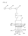
- a feedback process and system that measure the potential imparted to the photoconductive surface and then adjust the potential supplied to the charging corona array to compensate for irregularities that may exist from a predetermined norm.
- An electrometer measures the actual potential imparted to the photoconductive surface. The electrometer relays this information to a programmable logic controller (PLC) that compares the actual potential imparted to the photoconductive surface to that desired. As a result, the PLC then signals a variable potential power source connected to the corona charging array to make appropriate adjustment in the potential imparted thereto so as to result in the desired charge being imparted to the photoconductive surface by the corona charging array.
- PLC programmable logic controller
- the desired electrical charge is imparted to the photoconductive surface by a plurality of corona discharge wires that extend closely above the surface and are transversely oriented with respect to the movement direction of the surface.
- the wires are carried by and housed within a shield member that is provided with elongated channels, with each wire disposed in a channel.
- the shield member is removably mounted in brackets that extend transversely across and above the photoconductive surface.
- the shield is provided with flanges that slidably fit and are received within grooves formed in the bracket. Accordingly, the entire shield assembly with its associated corona charge wires may be readily detached from the printing press for purposes of cleaning, repair, etc.
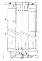
- FIG. 1 this view shows the overall organization of a typical photoconductive cylinder and associated mechanisms for formation of the latent electrostatic image, and subsequent image formation on the cylinder surface.
- a rotatable photoconductive drum 50 typically As2Se3 or SeTe, rotates in a counterclockwise direction as indicated by the arrow shown on cylinder 50 in Fig. 1.
- Special systems are arranged sequentially around drum 50 as shown in Fig. 1, to accomplish the desired formation and transfer of images onto web w. These systems include a high intensity charging apparatus 52, exposing-discharging (or imaging) apparatus 54, developing apparatus 55, transfer apparatus 56 and cleaning apparatus 58. These assure that the drum surface is charged, exposed, discharged and cleared of residual toner, while the developed images are continually transferred to the web material w.
- Charging apparatus 52 comprises a plurality of corona discharge devices comprising corona discharge wires 60 disposed within appropriately shaped shielded members 62 with each wire 60 and associated shield member 62 forming a separate focusing chamber 64. Although only two such corona discharge devices are shown in Fig. 1, in practice, five of same are employed (see Fig. 4) to help ensure that the proper potential is imparted to the photoconductive surface. It is to be appreciated that due to the rapid peripheral speed of drum 50, it is necessary to provide such a large array of corona charging means in light of the necessity of imparting a relatively high charge potential of the order specified to the photoconductive surface within the very short time provided for this task.
- the charge imparted by the coronas to the photoconductive cylinder is in the order of at least +1000 volts d.c., preferably between +1000 and +1450 volts. At present, a charge of +1100 v is clearly preferred.
- each of the corona charge wires 60 it is necessary to charge each of the corona charge wires 60 at +5600 to about +6500 v d.c.
- the corona assemblies extend across the drum surface 51 and along an arc closely parallel to surface 51. In a successful embodiment using a drum having a 33-inch circumference (thus 10.504-inch diameter) the arcuate length of the charging unit is about 4.5 inches or somewhat greater than 1/8 th of the drum circumference.
- a charge potential sensor 65 (an electrometer) which senses the voltage at the surface 55 and provides a continuous feedback signal to the charging power supply 67 to thereby adjust the charge level of the photoconductor surface 51 regardless of variations due, for example, to irregularities in the power supply or changes in the peripheral velocity of drum 50, drum shape irregularities or photoconductor wear and deterioration.
- the information sensed by sensor 65 is forwarded to a high speed amplifier 102 which receives the signal from sensor 65 and, as an output, forwards a voltage signal from 0-5 v to resistive capacitance network 104 which averages fluctuations in the signal over a time period of about 2.5 seconds.
- Network 104 is of conventional nature and may be referred to as a time constant RC network.
- the output from the RC network is a smooth signal that is forwarded to programmable logic controller 106 that is, for example, Texas Instruments Model 565.
- the signal received by the PLC 106 is compared to an expected normal signal that corresponds to, for example, +1100 v charge on the photoconductor surface.
- an expected normal signal that corresponds to, for example, +1100 v charge on the photoconductor surface.
- a signal is sent to the variable voltage power supply unit 67 to either increase or decrease potential output supplied to the corona discharge wires 60a, 60b, 60c, 60d, 60e, in parallel, so that the desired voltage (e.g., +1100 v) is imparted thereby to the photoconductor surface.
- Corona discharge wires 60a-e are each connected to resistors 108a-e prior to grounding of the wires.
- the resistors have resistances, each of about 3 megohms.
- the resistors are necessary in order to inhibit arcing that may otherwise occur due to the large potentials (i.e., +5600 v to +6800 v) impressed upon the wires in order to impart the correct voltages to the photoconductor.
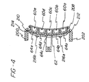
- Brackets 200, 202 are secured in frame members 204, 206 via screws or the like so that the brackets are slightly spaced from and extend transversely over the surface of drum 50. That is, the brackets extend in the axial direction of drum 50.
- the shield member 62 is generally arcuately shaped and is inserted into brackets 200, 202 via flanges 208, 210 that slide into corresponding recesses 212, 214 formed in the brackets.
- the shield member 62 is preferably formed of lightweight extruded aluminum with the brackets being composed of, for example, Delrin plastic. As shown, five corona discharge wires 60a-e are provided with each wire being disposed in and extending along a substantially "C" cross-sectioned channel 64a-e formed in the shield 62. The channels 64a-e are evenly spaced from each other and provide a separate housing for each wire 60a-e to ensure that the ions created by discharge wires 60a-e are properly deflected and directed onto the surface of drum 50 to provide for proper charging thereof.
- End-cap members 220, 222 are provided at endwise portions of the shield 62 and are secured thereto by the provision of screws 216a-d.
- the end-cap members are preferably made of plastic and serve to house the electrical leads thus securing same, fuses, and resistors that are also connected to the wires 60a-e.
- shield 62 the five evenly spaced channels thereof 64a-e, and the slidable mounting of the shield to the brackets 200, 202 provides for proper spacing of the wires 60a-e and easy service and repair of the entire charging unit.
- an imaging device 54 is mounted to extend transversely of the rotating drum surface 51.
- Light from the imaging device operates to discharge the background or non-image areas of the passing drum surface to a substantially lower potential, for example, in the order of +100 to +300 volts d.c. by exposing individual dot areas to radiation at a predetermined frequency, whereby the remaining or image areas comprise a latent electrostatic image of the printed portions of the form.
- drum 50 comprises an As2Se3 photoconductive layer to which charge coronas 52 impart a positive charge. Toner particles are accordingly provided with a negative charge in the range of about 60 to 75 picamhos/cm.
- transfer apparatus 56 as including a pair of idler rollers 90 which guide web W onto the "3 o'clock" location of drum 50, and behind the web path at this location is a transfer coratron 92.
- the web is driven at a speed equal to the velocity of drum surface 51, to minimize smudging or disturbance of the developed image on the surface 51. Both toner particles and liquid carrier transfer to the web, including carrier liquid on the drum surface 51 in the background areas.
Landscapes
- Physics & Mathematics (AREA)
- Engineering & Computer Science (AREA)
- Plasma & Fusion (AREA)
- General Physics & Mathematics (AREA)
- Electrostatic Charge, Transfer And Separation In Electrography (AREA)
Applications Claiming Priority (2)
| Application Number | Priority Date | Filing Date | Title |
|---|---|---|---|
| US442880 | 1989-11-29 | ||
| US07/442,880 US5017964A (en) | 1989-11-29 | 1989-11-29 | Corona charge system and apparatus for electrophotographic printing press |
Publications (2)
| Publication Number | Publication Date |
|---|---|
| EP0430648A2 true EP0430648A2 (fr) | 1991-06-05 |
| EP0430648A3 EP0430648A3 (en) | 1992-04-08 |
Family
ID=23758515
Family Applications (1)
| Application Number | Title | Priority Date | Filing Date |
|---|---|---|---|
| EP19900312882 Withdrawn EP0430648A3 (en) | 1989-11-29 | 1990-11-27 | Corona charge system and apparatus for electrophotographic printing press |
Country Status (3)
| Country | Link |
|---|---|
| US (1) | US5017964A (fr) |
| EP (1) | EP0430648A3 (fr) |
| CA (1) | CA2029813A1 (fr) |
Families Citing this family (4)
| Publication number | Priority date | Publication date | Assignee | Title |
|---|---|---|---|---|
| JP3019355B2 (ja) * | 1990-03-19 | 2000-03-13 | ミノルタ株式会社 | 画像形成装置 |
| JPH04251859A (ja) * | 1991-01-29 | 1992-09-08 | Murata Mach Ltd | 静電電位測定方法 |
| CA2076791C (fr) * | 1991-09-05 | 1999-02-23 | Mark A. Scheuer | Controle des pertes d'image dans un appareil d'imagerie a trois niveaux |
| US5526097A (en) * | 1995-06-07 | 1996-06-11 | Lexmark International, Inc. | Cartridge utilizing a plurality of contact charging members |
Family Cites Families (59)
| Publication number | Priority date | Publication date | Assignee | Title |
|---|---|---|---|---|
| BE590009A (fr) * | 1959-04-22 | 1900-01-01 | ||
| US3604925A (en) * | 1968-12-03 | 1971-09-14 | Zerox Corp | Apparatus for controlling the amount of charge applied to a surface |
| US3972305A (en) * | 1969-04-11 | 1976-08-03 | Xerox Corporation | Imaging system |
| US3599070A (en) * | 1969-09-17 | 1971-08-10 | Siltron | Battery charger and emergency power supply for illumination device |
| CA939732A (en) * | 1969-11-11 | 1974-01-08 | Masayoshi Furuichi | Apparatus for supplementing toner in electrophotographic machines |
| US4021586A (en) * | 1970-10-08 | 1977-05-03 | Canon Kabushiki Kaisha | Method of and means for the development of electrostatic images |
| US3900735A (en) * | 1971-09-10 | 1975-08-19 | Hoechst Ag | Corona discharge apparatus |
| US3736103A (en) * | 1971-09-20 | 1973-05-29 | Tec Systems | Incinerator combustion apparatus |
| US3739491A (en) * | 1971-09-22 | 1973-06-19 | Tec Systems | High velocity air web dryer |
| US4019055A (en) * | 1972-04-19 | 1977-04-19 | Xerox Corporation | Corona cleaning assembly |
| US3788739A (en) * | 1972-06-21 | 1974-01-29 | Xerox Corp | Image compensation method and apparatus for electrophotographic devices |
| JPS5434541B2 (fr) * | 1972-12-22 | 1979-10-27 | ||
| US3776440A (en) * | 1973-01-30 | 1973-12-04 | Tec Systems | Web handling apparatus |
| US3873013A (en) * | 1973-10-04 | 1975-03-25 | Tec Systems | High velocity web floating air bar having center exhaust means |
| US3934141A (en) * | 1974-07-03 | 1976-01-20 | Xerox Corporation | Apparatus for automatically regulating the amount of charge applied to an insulating surface |
| JPS5188230A (fr) * | 1975-01-31 | 1976-08-02 | ||
| US3964656A (en) * | 1975-04-14 | 1976-06-22 | Tec Systems, Inc. | Air bar assembly for web handling apparatus |
| US3961193A (en) * | 1975-05-27 | 1976-06-01 | Xerox Corporation | Self adjusting corona device |
| US4177730A (en) * | 1976-11-04 | 1979-12-11 | Harris Corporation | Method and apparatus for web printing |
| US4116620A (en) * | 1977-05-23 | 1978-09-26 | Tec Systems, Inc. | Web drying apparatus having means for heating recirculated air |
| JPS54628A (en) * | 1977-06-03 | 1979-01-06 | Ricoh Co Ltd | Multiple copying method for electronic copying apparatus |
| US4295383A (en) * | 1977-11-11 | 1981-10-20 | W. R. Grace & Co. | Variable speed drive |
| US4455562A (en) * | 1981-08-14 | 1984-06-19 | Pitney Bowes Inc. | Control of a light emitting diode array |
| US4182472A (en) * | 1978-07-13 | 1980-01-08 | W. R. Grace & Co. | Contactless turning guide for running webs |
| US4197972A (en) * | 1978-08-28 | 1980-04-15 | W. R. Grace & Co. | Contactless turning guide having air slots longitudinally along running web edges |
| US4197973A (en) * | 1978-10-12 | 1980-04-15 | W. R. Grace & Co. | High velocity web floating air bar having air flow straightening means for air discharge slot means |
| US4201323A (en) * | 1978-10-12 | 1980-05-06 | W. R. Grace & Co. | High velocity web floating air bar having a recessed Coanda plate |
| US4197971A (en) * | 1978-10-12 | 1980-04-15 | W. R. Grace & Co. | High velocity web floating air bar having an internal passage for transverse air discharge slot means |
| US4245272A (en) * | 1979-04-30 | 1981-01-13 | Eastman Kodak Company | Apparatus and method for low sensitivity corona charging of a moving photoconductor |
| US4286039A (en) * | 1979-05-15 | 1981-08-25 | Savin Corporation | Method and apparatus for removing excess developing liquid from photoconductive surfaces |
| US4310238A (en) * | 1979-09-08 | 1982-01-12 | Ricoh Company, Ltd. | Electrostatic copying apparatus |
| US4325627A (en) * | 1979-12-19 | 1982-04-20 | Savin Corporation | Method and apparatus for liquid-developing latent electrostatic images |
| US4265384A (en) * | 1980-01-21 | 1981-05-05 | W. R. Grace & Co. | Air bar having asymmetrical inlet |
| US4288015A (en) * | 1980-02-11 | 1981-09-08 | W. R. Grace & Co. | Contactless web turning guide |
| US4282998A (en) * | 1980-05-09 | 1981-08-11 | W. R. Grace & Co. | Maintenance of constant web clearance at contactless turning guide |
| US4343769A (en) * | 1980-08-11 | 1982-08-10 | W. R. Grace & Co. | Catalytic solvent vapor incinerating apparatus |
| US4432634A (en) * | 1980-10-20 | 1984-02-21 | Minolta Camera Kabushiki Kaisha | Electrophotographic copying apparatus |
| US4369584A (en) * | 1981-04-16 | 1983-01-25 | W. R. Grace & Co. | Preventing air film between web and roller |
| US4417804A (en) * | 1981-06-19 | 1983-11-29 | Xerox Corporation | High voltage comparator for photoreceptor voltage control |
| US4469428A (en) * | 1981-08-08 | 1984-09-04 | Mita Industrial Co., Ltd. | Corona discharging apparatus used in an electrostatic photographic copying machine |
| US4462169A (en) * | 1982-02-19 | 1984-07-31 | W. R. Grace & Company | Web dryer solvent vapor control means |
| US4425719A (en) * | 1982-03-15 | 1984-01-17 | W. R. Grace & Co. | Compact air bar assembly for contactless web support |
| US4399203A (en) * | 1982-04-15 | 1983-08-16 | The Standard Oil Company | Sulfide and selenide compositions |
| US4480859A (en) * | 1982-06-28 | 1984-11-06 | W. R. Grace & Co. | Flexible connector for flat wall ducting |
| US4564282A (en) * | 1982-11-15 | 1986-01-14 | Xerox Corporation | Corona charging device |
| US4474496A (en) * | 1983-01-24 | 1984-10-02 | W. R. Grace & Co. | Compact dryer for two web stretches |
| US4482624A (en) * | 1983-02-15 | 1984-11-13 | The Mead Corporation | Photosensitive material employing encapsulated radiation sensitive composition and process for improving sensitivity by sequestering oxygen |
| US4515292A (en) * | 1983-05-19 | 1985-05-07 | Burroughs Corporation | Digital implementation of toner concentration sensing apparatus |
| JPS6032074A (ja) * | 1983-08-03 | 1985-02-19 | Hitachi Metals Ltd | 現像装置 |
| JPS6147973A (ja) * | 1984-08-16 | 1986-03-08 | Ricoh Co Ltd | トナ−濃度制御方法 |
| US4563086A (en) * | 1984-10-22 | 1986-01-07 | Xerox Corporation | Copy quality monitoring for magnetic images |
| US4860924A (en) * | 1986-02-14 | 1989-08-29 | Savin Corporation | Liquid developer charge director control |
| US4631244A (en) * | 1986-02-18 | 1986-12-23 | E. I. Du Pont De Nemours And Company | Process for preparation of liquid toners for electrostatic imaging using polar additive |
| US4848633A (en) * | 1986-02-28 | 1989-07-18 | Thermo Electron Web Systems, Inc. | Non-contact web turning and drying apparatus |
| US4702985A (en) * | 1986-04-28 | 1987-10-27 | E. I. Du Pont De Nemours And Company | Aminoalcohols as adjuvant for liquid electrostatic developers |
| US4827315A (en) * | 1986-12-16 | 1989-05-02 | Larry Wolfberg | Printing press |
| US4760423A (en) * | 1987-03-12 | 1988-07-26 | Savin Corporation | Apparatus and method for reducing hydrocarbon emissions from a liquid-based electrophotographic copying machine |
| US4829336A (en) * | 1988-04-18 | 1989-05-09 | International Business Machines Corporation | Toner concentration control method and apparatus |
| US4828956A (en) * | 1988-05-02 | 1989-05-09 | Xerox Corporation | Processes for maintaining the triboelectric stability of electrophotographic developers |
-
1989
- 1989-11-29 US US07/442,880 patent/US5017964A/en not_active Expired - Fee Related
-
1990
- 1990-11-13 CA CA002029813A patent/CA2029813A1/fr not_active Abandoned
- 1990-11-27 EP EP19900312882 patent/EP0430648A3/en not_active Withdrawn
Also Published As
| Publication number | Publication date |
|---|---|
| EP0430648A3 (en) | 1992-04-08 |
| US5017964A (en) | 1991-05-21 |
| CA2029813A1 (fr) | 1991-05-30 |
Similar Documents
| Publication | Publication Date | Title |
|---|---|---|
| US5164779A (en) | Image forming apparatus with dual voltage supplies for selectively charging and discharging an image bearing member | |
| US5701551A (en) | Image forming apparatus including control means for controlling an output from en electrical power source to a charging member for charging an image bearing member | |
| EP0555102B1 (fr) | Appareil de formation d'images comprenant un élément de chargement en contact avec l'élément de support d'image | |
| US4432634A (en) | Electrophotographic copying apparatus | |
| US5243383A (en) | Image forming apparatus with predictive electrostatic process control system | |
| KR0168868B1 (ko) | 화상형성장치용 화상전사기구 | |
| JPH0772776A (ja) | 静電写真式単一経路型マルチステーションプリンタ | |
| US5926669A (en) | Image forming apparatus and method of forming an image with enhanced transfer condition settings | |
| US4003650A (en) | Controller for reproduction apparatus | |
| CA1066354A (fr) | Generateur de couronne pour electrocopieur couleur | |
| US5300984A (en) | Image forming apparatus having controlled transfer unit | |
| US3805069A (en) | Regulated corona generator | |
| US3891316A (en) | Multi-process control system for an electrophotographic printing machine | |
| EP0430648A2 (fr) | Système de chargement à effet corona et appareil pour une presse à imprimer électrophotographique | |
| US20090052915A1 (en) | Constant voltage leveling device for integrated charging system | |
| EP0531063B1 (fr) | ContrÔle de la perte de charge d'une zone image dans un appareil de formation d'images à trois niveaux | |
| KR100608053B1 (ko) | 전자사진방식 화상형성장치의 방전 시스템 및 방법 | |
| US5826138A (en) | Toner supply roller applied with a.c. voltage in nonmagnetic single component developing device | |
| US5008707A (en) | Simultaneous charging and exposure for pictorial quality | |
| JP2003131444A (ja) | 画像形成装置 | |
| US3822093A (en) | Transfer regulating apparatus | |
| US20060165438A1 (en) | Image forming apparatus | |
| US5457519A (en) | Two dimensional process control system for an electrostratographic printing machine | |
| JPH0239183A (ja) | 画像形成装置 | |
| US5881347A (en) | Biasing method and apparatus for electrostatically transferring an image |
Legal Events
| Date | Code | Title | Description |
|---|---|---|---|
| PUAI | Public reference made under article 153(3) epc to a published international application that has entered the european phase |
Free format text: ORIGINAL CODE: 0009012 |
|
| 17P | Request for examination filed |
Effective date: 19901208 |
|
| AK | Designated contracting states |
Kind code of ref document: A2 Designated state(s): BE CH DE ES FR GB IT LI LU NL SE |
|
| PUAL | Search report despatched |
Free format text: ORIGINAL CODE: 0009013 |
|
| AK | Designated contracting states |
Kind code of ref document: A3 Designated state(s): BE CH DE ES FR GB IT LI LU NL SE |
|
| 17Q | First examination report despatched |
Effective date: 19930709 |
|
| STAA | Information on the status of an ep patent application or granted ep patent |
Free format text: STATUS: THE APPLICATION IS DEEMED TO BE WITHDRAWN |
|
| 18D | Application deemed to be withdrawn |
Effective date: 19931120 |