EP0430710A2 - Vorrichtung zur Halterung eines Sensors - Google Patents
Vorrichtung zur Halterung eines Sensors Download PDFInfo
- Publication number
- EP0430710A2 EP0430710A2 EP90313063A EP90313063A EP0430710A2 EP 0430710 A2 EP0430710 A2 EP 0430710A2 EP 90313063 A EP90313063 A EP 90313063A EP 90313063 A EP90313063 A EP 90313063A EP 0430710 A2 EP0430710 A2 EP 0430710A2
- Authority
- EP
- European Patent Office
- Prior art keywords
- stream
- stem
- passage
- valve stem
- stems
- Prior art date
- Legal status (The legal status is an assumption and is not a legal conclusion. Google has not performed a legal analysis and makes no representation as to the accuracy of the status listed.)
- Withdrawn
Links
Images

Classifications
-
- G—PHYSICS
- G01—MEASURING; TESTING
- G01N—INVESTIGATING OR ANALYSING MATERIALS BY DETERMINING THEIR CHEMICAL OR PHYSICAL PROPERTIES
- G01N1/00—Sampling; Preparing specimens for investigation
- G01N1/02—Devices for withdrawing samples
- G01N1/10—Devices for withdrawing samples in the liquid or fluent state
- G01N1/20—Devices for withdrawing samples in the liquid or fluent state for flowing or falling materials
- G01N1/2035—Devices for withdrawing samples in the liquid or fluent state for flowing or falling materials by deviating part of a fluid stream, e.g. by drawing-off or tapping
-
- G—PHYSICS
- G01—MEASURING; TESTING
- G01N—INVESTIGATING OR ANALYSING MATERIALS BY DETERMINING THEIR CHEMICAL OR PHYSICAL PROPERTIES
- G01N21/00—Investigating or analysing materials by the use of optical means, i.e. using sub-millimetre waves, infrared, visible or ultraviolet light
- G01N21/01—Arrangements or apparatus for facilitating the optical investigation
- G01N21/03—Cuvette constructions
- G01N21/05—Flow-through cuvettes
-
- G—PHYSICS
- G01—MEASURING; TESTING
- G01N—INVESTIGATING OR ANALYSING MATERIALS BY DETERMINING THEIR CHEMICAL OR PHYSICAL PROPERTIES
- G01N21/00—Investigating or analysing materials by the use of optical means, i.e. using sub-millimetre waves, infrared, visible or ultraviolet light
- G01N21/84—Systems specially adapted for particular applications
- G01N21/85—Investigating moving fluids or granular solids
-
- G—PHYSICS
- G01—MEASURING; TESTING
- G01N—INVESTIGATING OR ANALYSING MATERIALS BY DETERMINING THEIR CHEMICAL OR PHYSICAL PROPERTIES
- G01N1/00—Sampling; Preparing specimens for investigation
- G01N1/02—Devices for withdrawing samples
- G01N1/10—Devices for withdrawing samples in the liquid or fluent state
- G01N1/20—Devices for withdrawing samples in the liquid or fluent state for flowing or falling materials
- G01N1/2035—Devices for withdrawing samples in the liquid or fluent state for flowing or falling materials by deviating part of a fluid stream, e.g. by drawing-off or tapping
- G01N2001/205—Devices for withdrawing samples in the liquid or fluent state for flowing or falling materials by deviating part of a fluid stream, e.g. by drawing-off or tapping using a valve
-
- G—PHYSICS
- G01—MEASURING; TESTING
- G01N—INVESTIGATING OR ANALYSING MATERIALS BY DETERMINING THEIR CHEMICAL OR PHYSICAL PROPERTIES
- G01N21/00—Investigating or analysing materials by the use of optical means, i.e. using sub-millimetre waves, infrared, visible or ultraviolet light
- G01N21/17—Systems in which incident light is modified in accordance with the properties of the material investigated
- G01N21/47—Scattering, i.e. diffuse reflection
- G01N21/49—Scattering, i.e. diffuse reflection within a body or fluid
- G01N21/53—Scattering, i.e. diffuse reflection within a body or fluid within a flowing fluid, e.g. smoke
Definitions
- This invention relates to a sensor-holding device and, more particularly, to a sensor-holding device which permits removal of sensors used for on-line measurements of a fluid stream flowing in a pipe without interrupting fluid flow.
- the present invention overcomes these problems by providing a sensor-holding device which allows for easy on-line maintenance or replacement of sensors without fluid stream shutdown.
- the device is useful for holding a wide variety of sensor types, including, but not limited to, light, ultrasonic, temperature and pressure sensors.
- the device provides stems which may be advanced and retracted independently so as to allow for both the adjustment of the distance between sensor windows or ends and adjustment of the position of the sensors in the fluid stream.
- One or both stems may be hollow to hold a one or two component sensor, respectively. When the stems are in their fully advanced positions, intimate and leak-proof contact of the stems is provided between the two mating stem surfaces. This permits the sensor elements to be removed for maintenance and reinstalled with no interruption of the fluid stream.
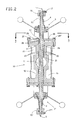
- the sensing apparatus includes a body 10 defining a fluid flow path 11 therethrough from an inlet end flange 12 to an outlet end flange 14 for connection to subsequent piping.
- the body may also be welded directly into an existing pipeline.
- Non-rotating hollow stems 4 and 6 are advanced and retracted by means of stem operating mechanisms 3 and 3′.
- 3 and 3′ are rising stem mechanisms assembled from nut 16 which is keyed to handle 17 by key 18. Washers 19 and 19′ are inserted between handle 17 and device body flange 53 and nut 20. Nut 20 is threaded onto 16 to secure the rising stem mechanism together.
- the sensor components consist of observation and illuminatioin probes 1 and 5 used for particle detection.
- An example of such a sensor is described in U.S. Patent No. 4,529,306.
- the probes 1 and 5 are contained in the hollow stems 4 and 6, respectively. They are held in place and maintained in a leak-tight condition by being either in a packing arrangement with or being threaded or gasketed into the stems 4 and 6. Probes 1 and 5 are further secured in the stems by means of caps 16 and 16′ and lock screws 17 and 17′.
- a packing arrangement is used to maintain stems 4 and 6 in a leaktight condition in device body 52. More particularly, the packing arrangement (Figs. 1 and 2) is assembled from bushing 21, packing rings 22 separated by metal waters 23, and sleeve 24 which acts as a packing follower. This packing arrangement may be compressed to effect a leaktight seal by tightening screws 25 and 25' which are threaded through plate 26 which presses against sleeve 24 and device body 52. This packing arrangement prevents fluid from the pipeline from leaking between the stems and the body of the device.
- the sensors 1 and 5 are recessed slightly into the holes in the stems 4 and 6 to prevent contact of the sensor faces when the device is in a closed position. Sensor ends in contact with the fluid may be provided with jewelled windows, as in the case of sensors using light, x-ray, or similar elements. Sensors which require direct contact with the fluid will not need this protection.
- the stems are advanced and retracted to expose the light path 51 to the flowing fluid path 11.
- the depth of view is varied by adjustment of the separation distance between the stems 4 and 6.
- the sampling zone may be varied by moving both stems simultaneously by equal distances in the desired direction.
- intimate contact of the stem 4 concave surface 7 and the stem 6 convex surface 8 isolates the sensor from the fluid flow path 11 and permits the removal, cleaning and reinstallation of the probes 1 and 5 while allowing fluid flow to continue uninterrupted.
- the device may be provided with a jacket means 15 for circulation of a heat transfer fluid if required to maintain the fluid in a molten or heated state, as in a polymer stream.
- stem surfaces 7 and 8 become fouled, a means is provided for cleaning these surfaces without the need for process stream shutdown.
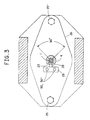
- Slot 27 is machined so as to allow for an approximately 90 degree rotation of stem 4. Key 28 prevents further rotation.
- stem 4 is caused to rotate back and forth relative to stem 6 while maintaining contact of the stem surfaces 7 and 8, thus wiping the surfaces to clean them.
- the arrangement of stem 6 is identical to that of stem 4, allowing for rotation of either or both of stems for cleaning purposes.
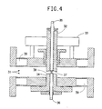
- Fig. 4 illustrates another embodiment of the present invention in which the stem 32 is movable but in which the seat 34 is fixed. Operation is similar to the embodiment given in Figs. 1-3.
- the stem 32 is advanced and retracted by means of stem operating mechanism 33 which may be identical to the rising stem mechanism illustrated in the embodiment of Figs. 1-3.
- Stem 32 may also be designed to provide for rotation relative to stem 34 for cleaning purposes as shown in the embodiment of Figs. 1-3.
- the depth of view may be adjusted by varying the position of the non-rotating stem 32 in the fluid path 31.
- intimate contact of the stem and seat surfaces 37 and 38 provides a leak-proof seal, thus allowing the removal, cleaning and reinstallation of the sensor probes 35 and 36.
- the device may also be provided with a jacket means 39 for circulation of heat transfer fluid if required.
- the above description is provided by way of example only.
- the sensor end, holding device stem and seat openings, and windows may be redesigned depending on the requirements of a particular sensor device to provide a leak-tight fit.
- a variety of seat/stem complementary mating configurations such as tapered, rounded, flat, convex/concave and concave/convex, are possible.
Landscapes
- Life Sciences & Earth Sciences (AREA)
- General Health & Medical Sciences (AREA)
- Health & Medical Sciences (AREA)
- Chemical & Material Sciences (AREA)
- Analytical Chemistry (AREA)
- Biochemistry (AREA)
- Physics & Mathematics (AREA)
- General Physics & Mathematics (AREA)
- Immunology (AREA)
- Pathology (AREA)
- Hydrology & Water Resources (AREA)
- Investigating Or Analyzing Materials By The Use Of Ultrasonic Waves (AREA)
- Sampling And Sample Adjustment (AREA)
- Examining Or Testing Airtightness (AREA)
Applications Claiming Priority (2)
| Application Number | Priority Date | Filing Date | Title |
|---|---|---|---|
| US07/444,778 US5069552A (en) | 1989-12-01 | 1989-12-01 | Sensor-holding device |
| US444778 | 1989-12-01 |
Publications (2)
| Publication Number | Publication Date |
|---|---|
| EP0430710A2 true EP0430710A2 (de) | 1991-06-05 |
| EP0430710A3 EP0430710A3 (en) | 1992-06-24 |
Family
ID=23766321
Family Applications (1)
| Application Number | Title | Priority Date | Filing Date |
|---|---|---|---|
| EP19900313063 Withdrawn EP0430710A3 (en) | 1989-12-01 | 1990-11-30 | Sensor-holding device |
Country Status (3)
| Country | Link |
|---|---|
| US (1) | US5069552A (de) |
| EP (1) | EP0430710A3 (de) |
| CA (1) | CA2031047A1 (de) |
Families Citing this family (4)
| Publication number | Priority date | Publication date | Assignee | Title |
|---|---|---|---|---|
| EP0540035A3 (en) * | 1991-10-31 | 1993-12-01 | Hughes Aircraft Co | Sensor for monitoring solutes in a liquid stream |
| AU7208196A (en) * | 1996-10-15 | 1998-05-11 | Renner Herrmann S.A. | Fluid analysis system and method, for analysing characteristic properties of a fluid |
| WO2002061400A1 (en) * | 2001-01-31 | 2002-08-08 | Sau Lan Tang Staats | Optical detection system for chromatographic and electrokinetic liquid phase separations |
| FR2903775B1 (fr) * | 2006-07-12 | 2009-01-16 | Tethys Instr Soc Par Actions S | Dispositif d'ecoulement d'un fluide et appareillage de mesure optique utilisant un tel dispositif. |
Family Cites Families (20)
| Publication number | Priority date | Publication date | Assignee | Title |
|---|---|---|---|---|
| US3020795A (en) * | 1959-05-14 | 1962-02-13 | Du Pont | Fluid inspection apparatus |
| US3584964A (en) * | 1967-12-15 | 1971-06-15 | Int Equipment Co | Spectrophotometer, flow cells and holders |
| US3728032A (en) * | 1971-10-13 | 1973-04-17 | H Noll | Flow cell for spectroscopic analysis of density gradients |
| US3810695A (en) * | 1972-12-14 | 1974-05-14 | Gam Rad | Fluid analyzer with variable light path |
| FR2231286A5 (de) * | 1973-05-21 | 1974-12-20 | Commissariat Energie Atomique | |
| US3886364A (en) * | 1973-06-19 | 1975-05-27 | Union Carbide Corp | High pressure infrared cell |
| US3936196A (en) * | 1974-10-21 | 1976-02-03 | Spectrotherm Corporation | Fluid chamber having manipulatable window elements |
| US4098119A (en) * | 1976-07-27 | 1978-07-04 | Coats William H | Sight-glass adapter |
| US4165179A (en) * | 1976-08-19 | 1979-08-21 | Nippon Precision Optical Instrument Co., Ltd. | Device for wiping optical window in turbidimeter or similar optical instrument for examining liquid sample |
| DE2838396A1 (de) * | 1978-09-02 | 1980-03-20 | Hartmann & Braun Ag | Optische sondenvorrichtung |
| BE880666A (fr) * | 1979-12-17 | 1980-04-16 | Centre Rech Metallurgique | Dispositif et procede pour mesurer l'emissivite d'un produit |
| GB2066947B (en) * | 1980-01-09 | 1984-06-20 | Measurex Corp | Gas measuring apparatus with adjustable path length and method for operation and standardization therefor |
| US4281935A (en) * | 1980-01-25 | 1981-08-04 | E. I. Du Pont De Nemours And Company | Additive injection valve |
| US4319138A (en) * | 1980-03-06 | 1982-03-09 | Shaban Manufacturing Ltd. | Housing for turbidimeter sensor |
| DE3104258A1 (de) * | 1981-02-07 | 1982-10-21 | Ruhrchemie Ag, 4200 Oberhausen | Vorrichtung zur messung von temperaturen in druckreaktoren |
| CA1199814A (en) * | 1981-11-25 | 1986-01-28 | Par H. Bergstrom | Device for measuring fluid consistency |
| US4516864A (en) * | 1982-12-27 | 1985-05-14 | General Electric Company | Non-contact sensing apparatus and method for polymer melt temperature profile determination |
| US4529306A (en) * | 1983-06-13 | 1985-07-16 | Flow Vision, Inc. | Apparatus and method for polymer melt stream analysis |
| DE3861563D1 (de) * | 1987-07-22 | 1991-02-21 | Ciba Geigy Ag | Prozesskuevette. |
| EP0302009A1 (de) * | 1987-07-22 | 1989-02-01 | Ciba-Geigy Ag | Prozessküvette |
-
1989
- 1989-12-01 US US07/444,778 patent/US5069552A/en not_active Expired - Lifetime
-
1990
- 1990-11-28 CA CA002031047A patent/CA2031047A1/en not_active Abandoned
- 1990-11-30 EP EP19900313063 patent/EP0430710A3/en not_active Withdrawn
Also Published As
| Publication number | Publication date |
|---|---|
| US5069552A (en) | 1991-12-03 |
| CA2031047A1 (en) | 1991-06-02 |
| EP0430710A3 (en) | 1992-06-24 |
Similar Documents
| Publication | Publication Date | Title |
|---|---|---|
| US5296197A (en) | Automated sample extractor or feeder/inoculator for bioreactors and similar equipment | |
| US5834657A (en) | Apparatus and methods for sensing fluid parameters | |
| US7389792B2 (en) | Dip tube valve assembly | |
| US5146792A (en) | Sampling device with a valve unit and a receiving unit | |
| US5905213A (en) | Liquid sampler having connecting device | |
| US6532981B2 (en) | Dip tube valve assembly | |
| US4606560A (en) | Thrust bearing rotary joint | |
| US5069552A (en) | Sensor-holding device | |
| JPH0720523U (ja) | 測定器用連結装置 | |
| US20040017569A1 (en) | System and method for sensing a characteristic of a fluid and related apparatus | |
| USRE37153E1 (en) | Variable pressure reducing device | |
| US20050253106A1 (en) | Drainable ferrule valve design | |
| US6000290A (en) | Quick-connect industrial process sensor | |
| US9285312B2 (en) | Reflection probe | |
| FR2748566A1 (fr) | Dispositif de prise d'echantillon sur une canalisation | |
| GB2105427A (en) | Erosion protection of pipework joints especially in a filtering system | |
| JPH0633829B2 (ja) | 弁組立体 | |
| WO1993002345A1 (en) | Isokinetic sampling apparatus | |
| US4085618A (en) | Composite sampling system and rotatable sampling valve therefor | |
| US5758692A (en) | Orifice fitting | |
| US20030133210A1 (en) | Changeable process window | |
| US5588467A (en) | Orifice fitting | |
| US20030019058A1 (en) | Process tapping point clearing apparatus | |
| SU1264035A1 (ru) | Устройство дл отбора проб жидкости | |
| USH1190H (en) | Analytical sampling valve |
Legal Events
| Date | Code | Title | Description |
|---|---|---|---|
| PUAI | Public reference made under article 153(3) epc to a published international application that has entered the european phase |
Free format text: ORIGINAL CODE: 0009012 |
|
| AK | Designated contracting states |
Kind code of ref document: A2 Designated state(s): DE ES GB |
|
| PUAL | Search report despatched |
Free format text: ORIGINAL CODE: 0009013 |
|
| AK | Designated contracting states |
Kind code of ref document: A3 Designated state(s): DE ES GB |
|
| 17P | Request for examination filed |
Effective date: 19921204 |
|
| 17Q | First examination report despatched |
Effective date: 19941223 |
|
| STAA | Information on the status of an ep patent application or granted ep patent |
Free format text: STATUS: THE APPLICATION IS DEEMED TO BE WITHDRAWN |
|
| 18D | Application deemed to be withdrawn |
Effective date: 19950905 |