EP0430740B1 - Plattenkühler für Hochöfen und eine aus solchen Kühlelementen zusammengesetzte Einrichtung - Google Patents
Plattenkühler für Hochöfen und eine aus solchen Kühlelementen zusammengesetzte Einrichtung Download PDFInfo
- Publication number
- EP0430740B1 EP0430740B1 EP90403169A EP90403169A EP0430740B1 EP 0430740 B1 EP0430740 B1 EP 0430740B1 EP 90403169 A EP90403169 A EP 90403169A EP 90403169 A EP90403169 A EP 90403169A EP 0430740 B1 EP0430740 B1 EP 0430740B1
- Authority
- EP
- European Patent Office
- Prior art keywords
- cooling
- plates
- cooling plate
- blast furnace
- plate
- Prior art date
- Legal status (The legal status is an assumption and is not a legal conclusion. Google has not performed a legal analysis and makes no representation as to the accuracy of the status listed.)
- Expired - Lifetime
Links
- 238000001816 cooling Methods 0.000 title claims abstract description 76
- 239000011819 refractory material Substances 0.000 claims abstract description 14
- 239000012530 fluid Substances 0.000 claims abstract description 6
- 239000011449 brick Substances 0.000 claims description 14
- 238000009434 installation Methods 0.000 claims description 10
- 239000012809 cooling fluid Substances 0.000 claims description 9
- 230000000903 blocking effect Effects 0.000 claims description 4
- 229920001971 elastomer Polymers 0.000 claims description 4
- 239000000806 elastomer Substances 0.000 claims description 4
- HBMJWWWQQXIZIP-UHFFFAOYSA-N silicon carbide Chemical compound [Si+]#[C-] HBMJWWWQQXIZIP-UHFFFAOYSA-N 0.000 claims description 4
- 229910010271 silicon carbide Inorganic materials 0.000 claims description 4
- 238000007789 sealing Methods 0.000 claims description 2
- 238000005266 casting Methods 0.000 claims 2
- 239000000463 material Substances 0.000 claims 2
- 238000012856 packing Methods 0.000 claims 2
- 230000002787 reinforcement Effects 0.000 claims 1
- 230000010485 coping Effects 0.000 abstract description 12
- 239000011248 coating agent Substances 0.000 abstract description 4
- 238000000576 coating method Methods 0.000 abstract description 4
- 239000002826 coolant Substances 0.000 abstract description 2
- 229910001018 Cast iron Inorganic materials 0.000 description 5
- 230000004907 flux Effects 0.000 description 5
- XLYOFNOQVPJJNP-UHFFFAOYSA-N water Substances O XLYOFNOQVPJJNP-UHFFFAOYSA-N 0.000 description 4
- 230000008901 benefit Effects 0.000 description 3
- 238000010276 construction Methods 0.000 description 3
- XEEYBQQBJWHFJM-UHFFFAOYSA-N Iron Chemical compound [Fe] XEEYBQQBJWHFJM-UHFFFAOYSA-N 0.000 description 2
- 229910000831 Steel Inorganic materials 0.000 description 2
- 239000002245 particle Substances 0.000 description 2
- 238000003908 quality control method Methods 0.000 description 2
- 230000003014 reinforcing effect Effects 0.000 description 2
- 230000008439 repair process Effects 0.000 description 2
- 230000000284 resting effect Effects 0.000 description 2
- 239000010959 steel Substances 0.000 description 2
- 230000000930 thermomechanical effect Effects 0.000 description 2
- XUIMIQQOPSSXEZ-UHFFFAOYSA-N Silicon Chemical compound [Si] XUIMIQQOPSSXEZ-UHFFFAOYSA-N 0.000 description 1
- 210000001015 abdomen Anatomy 0.000 description 1
- 238000005299 abrasion Methods 0.000 description 1
- 230000015572 biosynthetic process Effects 0.000 description 1
- 230000036760 body temperature Effects 0.000 description 1
- 230000008859 change Effects 0.000 description 1
- 230000001627 detrimental effect Effects 0.000 description 1
- 230000009977 dual effect Effects 0.000 description 1
- 238000004049 embossing Methods 0.000 description 1
- 238000010438 heat treatment Methods 0.000 description 1
- 238000004519 manufacturing process Methods 0.000 description 1
- 238000000034 method Methods 0.000 description 1
- 150000004767 nitrides Chemical group 0.000 description 1
- 238000005192 partition Methods 0.000 description 1
- 230000002093 peripheral effect Effects 0.000 description 1
- 230000001902 propagating effect Effects 0.000 description 1
- 230000001681 protective effect Effects 0.000 description 1
- 238000000275 quality assurance Methods 0.000 description 1
- 239000003507 refrigerant Substances 0.000 description 1
- 230000000630 rising effect Effects 0.000 description 1
- 238000000926 separation method Methods 0.000 description 1
- 239000000126 substance Substances 0.000 description 1
- FIAFUQMPZJWCLV-UHFFFAOYSA-N suramin Chemical compound OS(=O)(=O)C1=CC(S(O)(=O)=O)=C2C(NC(=O)C3=CC=C(C(=C3)NC(=O)C=3C=C(NC(=O)NC=4C=C(C=CC=4)C(=O)NC=4C(=CC=C(C=4)C(=O)NC=4C5=C(C=C(C=C5C(=CC=4)S(O)(=O)=O)S(O)(=O)=O)S(O)(=O)=O)C)C=CC=3)C)=CC=C(S(O)(=O)=O)C2=C1 FIAFUQMPZJWCLV-UHFFFAOYSA-N 0.000 description 1
- 238000009827 uniform distribution Methods 0.000 description 1
Images


Classifications
-
- C—CHEMISTRY; METALLURGY
- C21—METALLURGY OF IRON
- C21B—MANUFACTURE OF IRON OR STEEL
- C21B7/00—Blast furnaces
- C21B7/10—Cooling; Devices therefor
Definitions
- the present invention relates to a cooling plate used in metallurgical units whose walls are subjected to high heat fluxes such as for blast furnaces.
- the present invention also relates to a cooling installation using this type of plate.
- Modern blast furnaces are increasingly operated at speeds and pressure levels, such that the heat fluxes emitted can be, globally, locally and randomly important, and which it is necessary to capture and ensure their transfer, especially in the display areas, belly, bottom of tank, mid-tank and top of tank.
- the shield does not reach temperature levels or does not undergo temperature variations with the formation of thermomechanical stresses, which can jeopardize its resistance to mechanical resistance.
- the heat fluxes emitted in the different zones of the blast furnace must be captured by a heterogeneous system formed by the refractory lining, the cooling element, ie the cooling plate, the shielding, such that the cooling element fills a dual function of energetic cooling of the refractory and of screen for the passage of fluxes towards the shielding.
- the cooling plates can be brought and maintained at a certain temperature to fulfill functions of heating or maintaining body temperature in any particle size form in order to evacuate their water content or bring them at a temperature necessary for their use.
- the cooling plates consist of cast iron elements traversed in their mass by a network of tubes in which circulates a cooling flow which is generally water.
- These cooling tubes open on one side of the cooling plates and pass through the shield, outside of which they are connected either to each other or to cooling tubes of an adjacent upper or lower plate.
- the tubes thus connected determine the circulation lines of the fluid rising in a substantially vertical plane along the wall of the blast furnace, these lines being connected to an external circuit for circulation and cooling of the fluid.
- the cooling plates must be designed in such a way that they ensure good heat exchange with the cooling fluid and with the refractory lining, while creating a screen for the heat flow propagating from the furnace to the shielding.
- thermomechanical deformations and stresses resulting from high heat fluxes resist abrasion when the refractory lining has partially or completely disappeared and they must be able to be changed easily without having to enter the enclosure of the upper furnace.
- Cooling installations are known, in particular blast furnaces, the cooling plates of which consist of a cast iron element of substantially parallelepiped shape, in which are embedded longitudinal tubes arranged parallel to each other, these tubes opening onto the same main face, respectively in the upper and lower part of the cooling plate, in a protective sheath, one of the original characteristics of which is the embossed shape from the side opposite to that where the cooling tubes open.
- the cooling plates are lined with their refractory lining element directly on the steel site during the construction or repair of a blast furnace, which does not allow this operation to be carried out with all the care and quality controls. required.
- EP-A-0337 271 discloses a cooling panel for a shaft furnace comprising a cast iron plate in which are embedded cooling pipes opening on one of the main faces of the plate. A thick layer of refractory concrete is applied to the other main face of the plate before mounting it and is molded on said other face of the plate on a profiled structure to improve the bonding of said layer.
- US-A-1 376 617 is a hearth partition of an oven composed of a brick wall embedded in a box composed of a double envelope and in which a volume of water circulates.
- the box is made up of two parallelepiped boxes assembled one inside the other and having hollow horizontal and vertical peripheral walls.
- the subject of the present invention is a cooling installation having greater reliability, still ensuring uniformly and effective the role of screen in the passage of flows from the furnace to the shielding and allowing the refractory lining element to be placed directly in the workshop.
- the present invention thus relates to a cooling plate of a blast furnace in which circulates a cooling fluid by means of internal tubes, characterized in that it has the shape of a "C" whose branches define two curbs horizontal lines between which a coating element of refractory material is inserted.
- the present invention also relates to a cooling installation of a blast furnace using cooling plates defined above, said cooling plates being arranged in successive rings superimposed along the inner wall of the upper shield.
- the installation shown in FIG. 1 comprises a blast furnace 1, against the internal wall of which are placed cooling plates of which only the internal conduits have been shown connected to each other, designated by the general reference 2.
- the cooling plates indeed have internal tubes which open at different levels to the upper and lower parts of the latter, and are connected to the adjacent upper plate and to the plate adjacent immediately lower in a vertical plane, to define a circulation line formed by all of the internal tubes connected together.
- a circular supply line 3, surrounding the blast furnace at its bottom, comprises a set of individual supply lines 4 which are respectively connected. at the inputs 5 of the circulation lines 2.
- a circular return line 6, surrounding the blast furnace at a higher level, also comprises a set of individual return lines 7 connected to the outputs 8 of the circulation lines.
- This set of vertical circulation lines constitutes a network placed along the shielding of the blast furnace which is connected respectively at its lower part to the supply circular 3 and at the upper part to the return circular 6.
- This network of circulation lines is connected at each of its ends by means of the supply circulars 3 and return 6 to an external circuit, not shown.
- Fig.1 there is shown, for the sake of simplification, only a supply circular and a return circular for a circulation line of the refrigerant.
- the coolant which in the following description will be considered without limitation as being water, is introduced at different levels in the same vertical plane in different rows of the cooling plates.
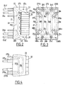
- each cooling plate 20 consists of a cast iron element of substantially parallelepiped shape having the shape of a "C" whose central part constitutes the body 21 of the plate and whose two branches define in the upper and lower part a curb 22 and 23 respectively horizontal and continuous.
- the inputs 25a, 25b, 25c ... and the outputs 26a, 26b, 26c ... are distributed over three levels so as to define in the body 21 an alternation of short tubes 24a, 24c and 24e and long tubes 24b and 24d.
- Each coping 22 and 23 is cooled for example by two transverse tubes 27a, 27b and 28a, 28a, 28b respectively arranged horizontally, the inlets 270a, 270b and 280a, 280b and the outlets 271a, 271b and 281a, 281b open onto the rear face of the cooling plate.
- the horizontal tubes 25a, 27b and 28a and 28b allow the angles of the cooling plate 20 to be cooled more intensely, and provide, with all of the longitudinal tubes, homogeneously, the role of a screen in the passage of heat flows, by effective cooling of each of the cooling plates 20 and of all the plates which are adjoining them.
- the number of horizontal tubes is a function of the position of the cooling plate 20 in the blast furnace.
- the section of the horizontal tubes 27a, 27b, 28a and 28b is such that it is possible, by sufficient circulation speeds, greater than 2 m / s, to capture the flows emitted without requiring large flow rates, or to generate abnormally high pressure drops .
- the speed of circulation of the cooling fluid in the vertical tubes 24a, 24b, 24c ... can be adjusted according to a cooling module.
- the front face of the plate 20 located between the coping 22 and 23 has an embossing 30 (Fig. 2) whose waves are filled with a good conductive refractory product 31 of small particle size.
- the thickness of the coping 22 and 23 is of the order of 200 mm.
- the brick 32a resting on the undercut 22a is a key brick blocking all of the refractory bricks.
- the bricks 32 can be mounted directly in the workshop during the manufacturing the plates with all the care and quality controls required, which cannot be perfectly applied during the usual period of construction or repairing the refractory walls of blast furnaces on the steel site.
- the refractory covering element can be monolithic, for example made of refractory concrete poured between the coping 22 and 23 and in this case the undercut 22a forms a notch for holding said element on the plate 20.
- this new generation of cooling plates makes it possible to obtain better contact between the cast iron and the refractory, a quality assurance of the implementation of the refractories and a saving of time during the operations of construction or repair of blast furnaces.
- Each coping 22 and 23 has on its hot face an insert 33, for example made of silicon carbide, in particular of trapezoidal cross section with dovetail, for reinforcing said hot face (FIG. 2).
- cooling plates 20 are arranged in successive rings A, B, C ... superimposed along the internal wall of the shield of the blast furnace and the internal tubes 24 of two adjacent plates in a vertical plane are interconnected so as to define a network of vertical circulation lines of the fluid, connected to the external circuit.
- the plates 20 of a crown on two are offset in a horizontal plane, relative to the plates 20 of the adjacent upper ring A and C, of a cooling fluid circulation tube so as to form over the major part of the surface determined by said cooling plates lines 40 of identical lengths.
- This definition makes it possible to obtain a uniform distribution of the cooling fluid.
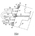
- Each plate 20 is fixed to the shield 41 using, on the one hand, a fixed point 42 for example in the lower part under controlled pressure on continuous seals 43 made of elastomer and insulating filling products 44 and, on the other hand, from a movable point 45 with sealing compensators 46 for example in the upper part of said plate 20 under controlled pressure on discontinuous seals 47 made of elastomer and insulating filling products 44.
- Welded washers 48 are provided between the inlets 25 of the tubes 24 and the shield 41 at the fixed points 42, while sliding washers 49 are provided between the outlets 26 of the tubes 24 at the mobile points 45.
- seals 50 which are mounted after placing said plates on the shield 41.
- These seals 50 are constituted by example of a fibrous putty.
- the installation according to the present invention makes it possible to have, for certain sensitive areas of the blast furnace, an even more efficient screen for the passage of heat flow, to irrigate the angular areas of the plates more intensely and to avoid the creation of 'more or less wide interfaces detrimental to heat transfer and conduction phenomenon through the assembly formed by the plates and the refractory wall.
- cooling plates avoids the separation of the refractory lining from its support on the hot face, which makes it possible to fully benefit from the physicochemical qualities of the refractories.
Landscapes
- Engineering & Computer Science (AREA)
- Chemical & Material Sciences (AREA)
- Manufacturing & Machinery (AREA)
- Materials Engineering (AREA)
- Metallurgy (AREA)
- Organic Chemistry (AREA)
- Blast Furnaces (AREA)
- Furnace Housings, Linings, Walls, And Ceilings (AREA)
- Vertical, Hearth, Or Arc Furnaces (AREA)
Claims (12)
- Kühlplatte eines Hochofens, in welcher eine Kühlflüssigkeit mittels interner Rohre (24a, 24b, 24c,..) strömt, dadurch gekennzeichnet, daß sie die Form eines "C" hat, dessen Schenkel zwei fortgesetzte horizontale Einfassungen (22, 23) definieren, zwischen denen ein Verkleidungselement aus hochschmelzendem Material eingesetzt ist.
- Kühlplatte nach Anspruch 1, dadurch gekennzeichent, daß wenigstens eine der Einfassungen (22, 23) eine Hinterschneidung (22a) zur Einspannung des Verkleidungselements aus hochschmelzendem Material aufweist.
- Kühlplatte nach den Ansprüchen 1 und 2, dadurch gekennzeichnet, daß das Verkleidungselement aus hochschmelzendem Material aus geformten hochschmelzenden Ziegeln (32) zusammengesetzt ist.
- Kühlplatte nach den Ansprüchen 1 und 2, dadurch gekennzeichnet, daß das Verkleidungselement aus hochschmelzendem Material monolithisch, hergestellt durch Gießen eines hochschmelzenden Betons in den durch die Einfassungen (22, 23) begrenzten Raum, ist.
- Kühlplatte nach den Ansprüchen 1 bis 3, dadurch gekennzeichnet, daß der an der Hinterschneidung (22a) anliegende Ziegel (32a) ein Schlüsselziegel, ist, der die Gesamtheit der Ziegel (32) des Verkleidungselement aus hochschmelzendem Material blockiert.
- Kühlplatte nach den Ansprüche 1, 2 und 4 dadurch gekennzeichnet, daß die Hinterschneidung, (22a) ein Ausschnitt zum Halten des monolithischen verkleidungselements ist.
- Kühlplatte nach Anspruch 2, dadurch gekennzeichnet, daß eine die Hinterschneidung (22a) aufweisende Einfassung (22) sich im oberen Teil der Kühlplatte (20) befindet.
- Kühlplatte nach Anspruch 1, dadurch gekennzeichnet, daß jede Einfassung (22, 23) eine horizontale Schicht aus wenigstens einem Kühlrohr (27a, 27b, 28a, 28b) in Abhänigkeit von ihrem Standort im Hochofen (1) aufweist.
- Kühlplatte nach Anspruch 1, dadurch gekennzeichnet, daß jede Einfassung (22, 23) auf ihrer heißen Seite einen Einsatz (33) mit einem zur Verstärkung der heißen Seite geeigneten Profil aufweist.
- Kühlplatte nach Anspruch 9, dadurch gekennzeichnet, daß der Einsatz (33) aus Siliziumkarbid ist.
- Einrichtung zur Kühlung eines Hochofens mit Hilfe von Kühlplatten nach einem der vorstehenden Ansprüche, wobei die Kühlplatten (20) in übereinander liegenden aufeinanderfolgenden Kränzen längs der Innenwand des Panzers (41) des Hochofens (1) angeordnet und von internen Rohren (24a, 24b, 24c..) durchsetzt sind, in denen eine Kühlflüssigkeit strömt, wobei die Eingänge (25a, 25b, 25c, ...) und die Ausgänge (26a, 26b, 26c...) der internen Rohre auf verschiedenen Höhen liegen, die internen Rohre (24a, 24b, 24c..) von zwei in einer vertikalen Ebene benachbarten Platten (20) miteinander so verbunden sind, daß ein Netz von den wesentlichen vertikalen Leitungen (40) für das Strömen der Flüssigkeit geschaffen wird, das mit einem äußeren Kreis verbunden ist, dadurch gekennzeichet, das die Platten (20) jedes Kranzes in Bezug auf die Platten (20) des benachbarten Kranzes in einer horizontalen Ebene um wenigstens ein Kühlrohr versetzt sind derart, daß auf dem größten Teil der Oberfläche der Platten (20) Leitungen (40) identischer Längen ausgebildet werden.
- Einrichtung nach Anspruch 11, dadurch gekennzeichnet, daß jede Kühlplatte (20) gegen den Panzer (41) des Hochofens unter kontrolliertem Druck mittels einerseits fester Punkte (42) im unteren oder oberen Teil der Platte (20) auf kontinuierlichen Dichtungen (43) aus Elastomer und Füllisolierstoffen (44) und anderseits beweglicher Punkte (45) mit Dichtungskompensator (46) in oberen oder unteren Teil der Platte (20) auf diskontinuierlichen Dichtungen (47) aus Elastomer und Füllisolierstoffen (44) festgelegt ist.
Applications Claiming Priority (2)
| Application Number | Priority Date | Filing Date | Title |
|---|---|---|---|
| FR8914936 | 1989-11-14 | ||
| FR8914936A FR2654438B1 (fr) | 1989-11-14 | 1989-11-14 | Plaques de refroidissement pour hauts-fourneaux et installation de refroidissement mettant en óoeuvre ce type de plaques. |
Publications (2)
| Publication Number | Publication Date |
|---|---|
| EP0430740A1 EP0430740A1 (de) | 1991-06-05 |
| EP0430740B1 true EP0430740B1 (de) | 1994-07-13 |
Family
ID=9387393
Family Applications (1)
| Application Number | Title | Priority Date | Filing Date |
|---|---|---|---|
| EP90403169A Expired - Lifetime EP0430740B1 (de) | 1989-11-14 | 1990-11-07 | Plattenkühler für Hochöfen und eine aus solchen Kühlelementen zusammengesetzte Einrichtung |
Country Status (7)
| Country | Link |
|---|---|
| US (1) | US5295666A (de) |
| EP (1) | EP0430740B1 (de) |
| JP (1) | JPH03183708A (de) |
| AT (1) | ATE108492T1 (de) |
| CA (1) | CA2029737A1 (de) |
| DE (1) | DE69010639T2 (de) |
| FR (1) | FR2654438B1 (de) |
Families Citing this family (7)
| Publication number | Priority date | Publication date | Assignee | Title |
|---|---|---|---|---|
| EP0705906B1 (de) * | 1994-10-07 | 2000-01-26 | Sms Schloemann-Siemag Aktiengesellschaft | Kühlplatte für Schachtöfen |
| DE19503912C2 (de) * | 1995-02-07 | 1997-02-06 | Gutehoffnungshuette Man | Kühlplatte für Schachtöfen, insbesondere Hochöfen |
| ATE205546T1 (de) * | 1995-05-05 | 2001-09-15 | Sms Demag Ag | Kühlplatten für schachtöfen |
| DE102008008477A1 (de) * | 2008-02-08 | 2009-08-13 | Sms Demag Ag | Kühlelement zur Kühlung der feuerfesten Auskleidung eines metallurgischen Ofens (AC,DC) |
| WO2017201172A1 (en) * | 2016-05-17 | 2017-11-23 | Berry Metal Company | Furnace stave |
| CN113957190B (zh) * | 2020-07-21 | 2022-10-21 | 宝山钢铁股份有限公司 | 一种高炉用冷却板及其维护方法 |
| CA3191845A1 (en) * | 2020-09-15 | 2022-03-24 | Arcelormittal | Blast furnace for ironmaking production |
Family Cites Families (12)
| Publication number | Priority date | Publication date | Assignee | Title |
|---|---|---|---|---|
| US1371906A (en) * | 1918-04-03 | 1921-03-15 | Blaw Knox Co | Water-cooler for furnaces |
| US1376617A (en) * | 1919-11-24 | 1921-05-03 | John O Griggs | Portable back wall for open-hearth furnaces |
| GB496289A (en) * | 1937-04-23 | 1938-11-23 | Brassert & Co | Improvements in and relating to refractory linings for shaft furnaces |
| JPS505125B1 (de) * | 1968-10-22 | 1975-02-28 | ||
| JPS5231282B2 (de) * | 1973-11-19 | 1977-08-13 | ||
| US4026352A (en) * | 1974-09-04 | 1977-05-31 | Sergei Mikhailovich Andoniev | Device for evaporative cooling of metallurgical units |
| SU590068A1 (ru) * | 1976-03-23 | 1978-01-30 | Каширский Литейный Завод "Центролит" | Плакированна смесь дл изготовлени литейных оболочковых форм и стержней,отверждаемых при контракте с гор чей оснасткой |
| FR2458591A1 (fr) * | 1979-06-06 | 1981-01-02 | Technilor | Etancheite aux gaz sur plaques de refroidissement interieures et sur paroi exterieure de blindages de hauts fourneaux |
| FR2526928A1 (fr) * | 1982-05-14 | 1983-11-18 | Inst Proekt Metallu | Dispositif de refroidissement de la paroi d'un four metallurgique |
| JPS6335708A (ja) * | 1986-07-31 | 1988-02-16 | Nippon Steel Corp | 高炉炉体保護壁 |
| LU87198A1 (fr) * | 1988-04-13 | 1989-11-14 | Wurth Paul Sa | Panneau de refroidissement pour four a cuve |
| JPH0663012B2 (ja) * | 1988-08-10 | 1994-08-17 | 川崎製鉄株式会社 | 高炉炉体保護壁 |
-
1989
- 1989-11-14 FR FR8914936A patent/FR2654438B1/fr not_active Expired - Fee Related
-
1990
- 1990-11-07 AT AT90403169T patent/ATE108492T1/de not_active IP Right Cessation
- 1990-11-07 DE DE69010639T patent/DE69010639T2/de not_active Expired - Fee Related
- 1990-11-07 EP EP90403169A patent/EP0430740B1/de not_active Expired - Lifetime
- 1990-11-13 CA CA002029737A patent/CA2029737A1/fr not_active Abandoned
- 1990-11-14 JP JP2308446A patent/JPH03183708A/ja active Pending
-
1992
- 1992-12-02 US US07/985,237 patent/US5295666A/en not_active Expired - Fee Related
Also Published As
| Publication number | Publication date |
|---|---|
| US5295666A (en) | 1994-03-22 |
| DE69010639D1 (de) | 1994-08-18 |
| EP0430740A1 (de) | 1991-06-05 |
| ATE108492T1 (de) | 1994-07-15 |
| JPH03183708A (ja) | 1991-08-09 |
| CA2029737A1 (fr) | 1991-05-15 |
| DE69010639T2 (de) | 1995-03-16 |
| FR2654438B1 (fr) | 1994-04-01 |
| FR2654438A1 (fr) | 1991-05-17 |
Similar Documents
| Publication | Publication Date | Title |
|---|---|---|
| CA2119596C (fr) | Procede et dispositif pour la fusion du verre | |
| FR2493871A1 (fr) | Plaques de refroidissement pour hauts fourneaux | |
| EP0228918A1 (de) | Verfahren zur Herstellung feuerfest zugestellter Wände für Öfen und Brennkammern und Stein dafür | |
| CH627834A5 (fr) | Paroi refroidie d'un four a arc. | |
| EP0430740A1 (de) | Plattenkühler für Hochöfen und eine aus solchen Kühlelementen zusammengesetzte Einrichtung | |
| EP0090761B1 (de) | Rinne für eine Metallschmelze | |
| EP0618301B1 (de) | Vorrichtung zum Einblasen vorgewärmter Luft in einen Schachtofen | |
| EP2751051B1 (de) | Stopfmasse für die feuerfeste auskleidung eines metallurgischen gefässes, metallurgisches gefäss, beispielsweise ein hochofen, das eine auskleidung umfasst, die die genannte stopfmasse verwendet | |
| FR2516536A1 (fr) | Four de craquage a tubes pour le chauffage indirect de milieux aptes au craquage | |
| FR2707791A1 (fr) | Ecran pour le système de refroidissement par air entre cuve et silo dans un réacteur nucléaire. | |
| FR2526810A1 (fr) | Appareil cowper muni d'une double enveloppe creuse pour hauts fourneaux | |
| EP0012132A1 (de) | Metallische Kühlelemente für Industrieöfen | |
| EP4010651A1 (de) | Verbesserter wärmespeicher | |
| LU87198A1 (fr) | Panneau de refroidissement pour four a cuve | |
| FR2526928A1 (fr) | Dispositif de refroidissement de la paroi d'un four metallurgique | |
| EP1856468A2 (de) | Feuerfeste platte, insbesondere für vergaser | |
| BE897590A (fr) | Elements moules d'isolation destines au revetement de conduits refroidis de chaufferies | |
| EP0021919A1 (de) | Vorrichtung zum Befestigen und Abdichten von Kühlplatten am Hochofen | |
| FR2507757A1 (fr) | Cuve comportant des supports destines a des pieces internes | |
| FR2521702A1 (fr) | Dispositif de refroidissement de la paroi conique d'un four a cuve | |
| EP0015351B2 (de) | Verbindungsrohr zwischen dem Inneren und dem Äusseren eines Ofens | |
| WO2024089054A1 (fr) | Four verrier | |
| LU88629A1 (fr) | Garnissage de protection en briques rétractaires pour un caisson de refroidissement d'un four industriel | |
| FR2458775A1 (fr) | Revetement pour des tubes situes dans des espaces de chauffe de fours industriels | |
| BE557186A (de) |
Legal Events
| Date | Code | Title | Description |
|---|---|---|---|
| PUAI | Public reference made under article 153(3) epc to a published international application that has entered the european phase |
Free format text: ORIGINAL CODE: 0009012 |
|
| 17P | Request for examination filed |
Effective date: 19910402 |
|
| AK | Designated contracting states |
Kind code of ref document: A1 Designated state(s): AT BE CH DE DK ES FR GB GR IT LI LU NL SE |
|
| 17Q | First examination report despatched |
Effective date: 19930322 |
|
| RAP1 | Party data changed (applicant data changed or rights of an application transferred) |
Owner name: FORCAST INTERNATIONAL |
|
| GRAA | (expected) grant |
Free format text: ORIGINAL CODE: 0009210 |
|
| ITF | It: translation for a ep patent filed | ||
| AK | Designated contracting states |
Kind code of ref document: B1 Designated state(s): AT BE CH DE DK ES FR GB GR IT LI LU NL SE |
|
| PG25 | Lapsed in a contracting state [announced via postgrant information from national office to epo] |
Ref country code: NL Effective date: 19940713 Ref country code: GR Free format text: LAPSE BECAUSE OF FAILURE TO SUBMIT A TRANSLATION OF THE DESCRIPTION OR TO PAY THE FEE WITHIN THE PRESCRIBED TIME-LIMIT Effective date: 19940713 Ref country code: ES Free format text: THE PATENT HAS BEEN ANNULLED BY A DECISION OF A NATIONAL AUTHORITY Effective date: 19940713 Ref country code: DK Effective date: 19940713 Ref country code: AT Effective date: 19940713 |
|
| REF | Corresponds to: |
Ref document number: 108492 Country of ref document: AT Date of ref document: 19940715 Kind code of ref document: T |
|
| GBT | Gb: translation of ep patent filed (gb section 77(6)(a)/1977) |
Effective date: 19940712 |
|
| REF | Corresponds to: |
Ref document number: 69010639 Country of ref document: DE Date of ref document: 19940818 |
|
| PG25 | Lapsed in a contracting state [announced via postgrant information from national office to epo] |
Ref country code: SE Effective date: 19941013 |
|
| PG25 | Lapsed in a contracting state [announced via postgrant information from national office to epo] |
Ref country code: LU Free format text: LAPSE BECAUSE OF NON-PAYMENT OF DUE FEES Effective date: 19941130 |
|
| NLV1 | Nl: lapsed or annulled due to failure to fulfill the requirements of art. 29p and 29m of the patents act | ||
| PLBE | No opposition filed within time limit |
Free format text: ORIGINAL CODE: 0009261 |
|
| STAA | Information on the status of an ep patent application or granted ep patent |
Free format text: STATUS: NO OPPOSITION FILED WITHIN TIME LIMIT |
|
| 26N | No opposition filed | ||
| REG | Reference to a national code |
Ref country code: GB Ref legal event code: IF02 |
|
| PGFP | Annual fee paid to national office [announced via postgrant information from national office to epo] |
Ref country code: CH Payment date: 20041015 Year of fee payment: 15 |
|
| PGFP | Annual fee paid to national office [announced via postgrant information from national office to epo] |
Ref country code: LU Payment date: 20041018 Year of fee payment: 15 |
|
| PGFP | Annual fee paid to national office [announced via postgrant information from national office to epo] |
Ref country code: GB Payment date: 20041022 Year of fee payment: 15 |
|
| PGFP | Annual fee paid to national office [announced via postgrant information from national office to epo] |
Ref country code: DE Payment date: 20041109 Year of fee payment: 15 |
|
| PGFP | Annual fee paid to national office [announced via postgrant information from national office to epo] |
Ref country code: FR Payment date: 20041116 Year of fee payment: 15 |
|
| PGFP | Annual fee paid to national office [announced via postgrant information from national office to epo] |
Ref country code: BE Payment date: 20041208 Year of fee payment: 15 |
|
| PG25 | Lapsed in a contracting state [announced via postgrant information from national office to epo] |
Ref country code: IT Free format text: LAPSE BECAUSE OF NON-PAYMENT OF DUE FEES;WARNING: LAPSES OF ITALIAN PATENTS WITH EFFECTIVE DATE BEFORE 2007 MAY HAVE OCCURRED AT ANY TIME BEFORE 2007. THE CORRECT EFFECTIVE DATE MAY BE DIFFERENT FROM THE ONE RECORDED. Effective date: 20051107 Ref country code: GB Free format text: LAPSE BECAUSE OF NON-PAYMENT OF DUE FEES Effective date: 20051107 |
|
| PG25 | Lapsed in a contracting state [announced via postgrant information from national office to epo] |
Ref country code: LI Free format text: LAPSE BECAUSE OF NON-PAYMENT OF DUE FEES Effective date: 20051130 Ref country code: CH Free format text: LAPSE BECAUSE OF NON-PAYMENT OF DUE FEES Effective date: 20051130 Ref country code: BE Free format text: LAPSE BECAUSE OF NON-PAYMENT OF DUE FEES Effective date: 20051130 |
|
| PG25 | Lapsed in a contracting state [announced via postgrant information from national office to epo] |
Ref country code: DE Free format text: LAPSE BECAUSE OF NON-PAYMENT OF DUE FEES Effective date: 20060601 |
|
| REG | Reference to a national code |
Ref country code: CH Ref legal event code: PL |
|
| GBPC | Gb: european patent ceased through non-payment of renewal fee |
Effective date: 20051107 |
|
| PG25 | Lapsed in a contracting state [announced via postgrant information from national office to epo] |
Ref country code: FR Free format text: LAPSE BECAUSE OF NON-PAYMENT OF DUE FEES Effective date: 20060731 |
|
| REG | Reference to a national code |
Ref country code: FR Ref legal event code: ST Effective date: 20060731 |
|
| BERE | Be: lapsed |
Owner name: *FORCAST INTERNATIONAL Effective date: 20051130 |