EP0430792B1 - Perfectionnement aux dispositifs de commande multiflexée d'un ensemble d'organes électriques d'un véhicule automobile - Google Patents
Perfectionnement aux dispositifs de commande multiflexée d'un ensemble d'organes électriques d'un véhicule automobile Download PDFInfo
- Publication number
- EP0430792B1 EP0430792B1 EP90403354A EP90403354A EP0430792B1 EP 0430792 B1 EP0430792 B1 EP 0430792B1 EP 90403354 A EP90403354 A EP 90403354A EP 90403354 A EP90403354 A EP 90403354A EP 0430792 B1 EP0430792 B1 EP 0430792B1
- Authority
- EP
- European Patent Office
- Prior art keywords
- lamp
- module
- controlled
- switches
- electrical
- Prior art date
- Legal status (The legal status is an assumption and is not a legal conclusion. Google has not performed a legal analysis and makes no representation as to the accuracy of the status listed.)
- Expired - Lifetime
Links
Images



Classifications
-
- F—MECHANICAL ENGINEERING; LIGHTING; HEATING; WEAPONS; BLASTING
- F21—LIGHTING
- F21S—NON-PORTABLE LIGHTING DEVICES; SYSTEMS THEREOF; VEHICLE LIGHTING DEVICES SPECIALLY ADAPTED FOR VEHICLE EXTERIORS
- F21S43/00—Signalling devices specially adapted for vehicle exteriors, e.g. brake lamps, direction indicator lights or reversing lights
- F21S43/10—Signalling devices specially adapted for vehicle exteriors, e.g. brake lamps, direction indicator lights or reversing lights characterised by the light source
- F21S43/19—Attachment of light sources or lamp holders
- F21S43/195—Details of lamp holders, terminals or connectors
-
- H—ELECTRICITY
- H05—ELECTRIC TECHNIQUES NOT OTHERWISE PROVIDED FOR
- H05B—ELECTRIC HEATING; ELECTRIC LIGHT SOURCES NOT OTHERWISE PROVIDED FOR; CIRCUIT ARRANGEMENTS FOR ELECTRIC LIGHT SOURCES, IN GENERAL
- H05B47/00—Circuit arrangements for operating light sources in general, i.e. where the type of light source is not relevant
- H05B47/10—Controlling the light source
- H05B47/175—Controlling the light source by remote control
- H05B47/18—Controlling the light source by remote control via data-bus transmission
-
- H—ELECTRICITY
- H05—ELECTRIC TECHNIQUES NOT OTHERWISE PROVIDED FOR
- H05B—ELECTRIC HEATING; ELECTRIC LIGHT SOURCES NOT OTHERWISE PROVIDED FOR; CIRCUIT ARRANGEMENTS FOR ELECTRIC LIGHT SOURCES, IN GENERAL
- H05B47/00—Circuit arrangements for operating light sources in general, i.e. where the type of light source is not relevant
- H05B47/10—Controlling the light source
- H05B47/175—Controlling the light source by remote control
- H05B47/198—Grouping of control procedures or address assignation to light sources
- H05B47/1985—Creation of lighting zones or scenes
-
- B—PERFORMING OPERATIONS; TRANSPORTING
- B60—VEHICLES IN GENERAL
- B60R—VEHICLES, VEHICLE FITTINGS, OR VEHICLE PARTS, NOT OTHERWISE PROVIDED FOR
- B60R16/00—Electric or fluid circuits specially adapted for vehicles and not otherwise provided for; Arrangement of elements of electric or fluid circuits specially adapted for vehicles and not otherwise provided for
- B60R16/02—Electric or fluid circuits specially adapted for vehicles and not otherwise provided for; Arrangement of elements of electric or fluid circuits specially adapted for vehicles and not otherwise provided for electric constitutive elements
- B60R16/03—Electric or fluid circuits specially adapted for vehicles and not otherwise provided for; Arrangement of elements of electric or fluid circuits specially adapted for vehicles and not otherwise provided for electric constitutive elements for supply of electrical power to vehicle subsystems or for
- B60R16/0315—Electric or fluid circuits specially adapted for vehicles and not otherwise provided for; Arrangement of elements of electric or fluid circuits specially adapted for vehicles and not otherwise provided for electric constitutive elements for supply of electrical power to vehicle subsystems or for using multiplexing techniques
Definitions
- the present invention relates generally to devices for controlling electrical components, in particular in motor vehicles, and more particularly the multiplexed control of a plurality of such electrical components.
- an optical unit for example a block of vehicle rear lights, comprises a plurality of lights (position, stop, flashing, reversing, rear fog), the lamps of which are all connected to a common ground and are each powered by a driver extending between the lamp supply terminal and a specific switch or switch located on the dashboard.
- a so-called multiplexed control device for a group of lights has been developed in which a single supply line arrives at the block of lights, while a control line carries a low current signal containing ignition instructions or of each fire.
- a specialized electronic decoding or demultiplexing circuit is responsible for recognizing the instructions contained in these signals and to consequently command switch means, such as relays or preferably power semiconductors, to selectively turn on or off the lamps of each of the lights.
- the decoding module and the power semiconductors are integrated into a single assembly, either incorporated in the block of lights, or in the form of a separate unit located in the vehicle near said block.
- a main drawback of this known solution lies in the practical impossibility of producing a single standard assembly for the various types of vehicle light units. Indeed, between low-end and high-end vehicles, in particular, the number of lights or searchlights in a front or rear light unit, and the functions to be performed, vary quite widely.
- the decoding module must be specially designed to be able to withstand the harsh thermal environment caused by the dissipation of heat in the power switches.
- the present invention aims to overcome the drawbacks of the prior art and for this purpose proposes a device for controlling a set of electrical components, in particular in a motor vehicle, of the type comprising for a group of such components a receiving decoding module an electrical signal containing instructions for excitation and de-excitation of the group's electrical components and creating control signals from said setpoints, and a set of switches controlled by said control signals and each mounted between an electrical supply line common and a respective electrical member of the group, characterized in that the controlled switches are mounted near each of the respective electrical members of the group and in that the decoding module is housed in a housing separate from the controlled switches.
- the controlled switches are mounted on or in means of connection with said members.
- connection means for a device as defined above, characterized in that it comprises an adaptation element capable of cooperating mechanically with a predefined connection element of an electrical member controlled by the device , said adaptation element being integral with a controlled switch module, the connecting means simultaneously allowing the mounting of the electrical member in the device and the switching on of the controlled switch.
- FIG. 1 there is shown a rear optical unit of a motor vehicle, generally indicated in B, which comprises four lamps L1, L2, L3, L4.
- the L1 lamp is a lamp with two filaments for the "position light” and "stop light” functions.
- the lamps L2 to L4 are for example flashing light, reversing light and rear fog light lamps, respectively.
- the lamps are preferably mounted, in a conventional manner, on a common lamp holder (not shown) comprising cut circuits or printed circuits supply and means for fixing the lamps in sockets in their appropriate positions, the ground terminals of each of the lamps being permanently connected to a common ground.
- An encoding or multiplexing device 100 located for example in the region of the vehicle dashboard, is connected to a set of switches, selectors and / or control switches (not shown individually) provided on said dashboard and intended for the control by the user of switching the lights on and off, this assembly being schematically indicated at 110.
- the encoding module 100 Depending on the states of the various control members of the assembly 110, the encoding module 100 generates on a bus 120 constituted by a pair of conductors 121, 122 a multiplexed electrical signal representative of the respective states of said members and, consequently, instructions for switching on and off the various lamps in the optical unit.
- This bus 120 as well as a single supply line 130 carrying for example a voltage of +12 volts DC supplied by a battery 140, are brought to the vicinity of the optical unit B.
- bus 120 and the supply line 130 run through all the points of the vehicle where such electrical devices are located).
- the device firstly comprises a decoding or demultiplexing module 200 which is housed in a housing 202 located outside the optical unit itself but preferably close to it.
- This decoding module produced for example in the form of a specialized integrated circuit single, powered by the +12 volts present on line 130, includes an input for receiving the signal generated on the bus 120 by the encoding module 100 and a set of control outputs (five in number in this example) to which five respective control lines LC1, LC1 ′, LC2, LC3 and LC4 are connected for controlling the various lamps of the optical unit B.
- the optical unit B comprises, on a suitable support (not shown in FIG. 1) and in the vicinity of each of the lamps, controlled switches, preferably in the form of power semiconductor components.
- Each switch includes a current input terminal, a current output terminal, and a control signal input terminal.
- the current input terminals of each of the controlled switches are connected in common to the supply line 130.
- the current output terminals are connected to the respective positive terminals of the associated lamps (to the two positive terminals of the respective filaments of the lamp L1 for the components I1 and I1 ')
- control signal input terminals of components I1, I1 ', I2, I3 and I4 are in turn connected to the control lines LC1, LC1', LC2, LC3 and LC4.
- the power components are mounted, optionally removably (by plugging in or the like), on the lamp holder of the optical unit, near each respective lamp location.
- the device of the present invention operates as follows.
- the driver acts on an appropriate control member of the assembly 110 to switch on or off one of the lights of the optical unit B (and if necessary the same light on a second optical unit)
- the coding module 100 detects this action and modifies the multiplexed control signal accordingly.
- the decoding module detects this change and, consequently, orders the power component concerned via the associated command line to close or open this component, according to the order passed, and thus turn the lamp on or off. of the fire considered.
- the decoding module can thanks to the present invention be standardized.
- three types of lamp are currently mainly used in vehicle rear lights, namely 5 watt monofilament lamps, 21 watt monofilament lamps and bi-filament lamps of 5 watt and 21 watt respectively.
- three types of modular sub-assemblies can be produced, each constituting, possibly in association with a specific arrangement of the lamp holder, a lamp socket and each comprising, depending on the type of lamp that the socket is to receive, a or two power components sized according to the intensity which must pass through the associated filament, the subassembly being organized in the form of a module suitable for being connected on the one hand to the lamp and on the other hand to the line power supply (line 130 in Figure 1), the mass and the associated command line from the decoding module.
- line power supply line 130 in Figure 1
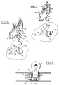
- FIG. 2a is shown schematically such a module M, which is suitable for a monofilament lamp L.
- a monofilament lamp L Two versions of such a module are in practice produced, one for a 5 watt lamp and the other for a 21 watt lamp. watts, the power component I being sized according to the maximum current likely to flow in the lamp.
- FIG. 2b is illustrated a module M 'for a lamp L' with two filaments, with two power components I 'and I' 'dimensioned respectively for the filament of 5 watts and for the filament of 21 watts.
- Each power component has its own input for the command line from the decoding module.
- any combination of the three aforementioned basic modules can be used, only the number and distribution of the modules varying between different optical units. Furthermore, these modules can be produced with a very small footprint and their installation on the body of the optical unit is facilitated.
- the power components are of the "intelligent" type.
- they are capable not only of reacting to the control signal sent to them by the decoding module to selectively supply the lamp or disconnect it from the supply line, but they also have an ability to warn the decoding module of possible failures either of the lamp or of the component itself.
- the command line between the decoding module and the component is bidirectional in its capacity to transmit information.
- the fault information received from the intelligent power component by the decoding module must be transmitted to the coding module, integrated in the central unit of the multiplexed control of the vehicle functions; the control bus 120 is also designed to allow this bidirectional exchange of data between the decoding module and the central unit, and more generally between all of the decoding modules provided in the vehicle and said central unit.
- FIGS. 3 to 15 of concrete embodiments of lamp holder / power switch module associations in accordance with the present invention.
- Figures 3 to 6 and 10 to 13 relate to a transverse arrangement of the module relative to the axis of the lamp, while Figures 7 to 9 and 14, 15 relate to a mounting of the modules in a plane parallel to said axis.
- FIG. 3 illustrates a first example of a module M for a single lamp, produced in the form of an integrated power circuit.
- This circuit is housed in a housing 10 fixed on a support plate 12.
- a ground connector 14 extends upwards from one end of the housing and comprises a contact part 15 folded down and curved intended to come into contact with the base C of the lamp.
- a positive voltage connector 16 extends from the other end of the housing 10 substantially against the upper face of the latter, and comprises a contact portion 17 folded back, curved and intended to come into contact with the central lamp supply stud.
- connection pins 18, corresponding to the four terminals shown in FIG. 2a, extend downward two by two respectively from the two lateral faces of the housing 10.
- FIG. 4 illustrates a practical embodiment of a module M 'shown schematically in Figure 2b.
- the references used in FIG. 3 are supplemented here by a "premium", by designating identical or similar parts.
- the two types of modules M and M ′ in FIGS. 3 and 4 have identical external dimensions, so as to be able to adapt in housings of unique design provided for both monofilament lamps and bifilament lamps.
- FIG. 5 illustrates the module M ′ from FIG. 4, turned over, as well as an associated socket structure 22 formed in a lamp holder 20.
- the structure 22 includes a cylindrical passage 24 for the base C of the lamp; a groove 26 runs along said cylindrical passage 24 to receive the ground conductor 14 ', 15'.
- the passage 24 ends in an essentially parallelepiped housing 28 for receiving the module M '.
- Two lateral clearances 30 of the housing 28 allow the lateral pins 18 ′ to be received, while an end clearance 32 makes it possible to receive the part of the support 12 ′ which projects beyond the housing 10 ′.
- Arrangements of conventional design (bayonet or the like) for fixing the lamp in the socket have not been shown.
- FIG. 6 shows a part of a lamp holder 20 showing the association of a socket structure 22 and a module M, together forming a socket, a monofilament lamp L and a PCB printed circuit.
- the module M and the lamp L have been installed respectively from the inside and the outside of the lamp holder (from below and from above in FIG. 6), while the printed circuit CI is fixed by any means suitable on the inside of the lamp holder.
- This printed circuit comprises the appropriate tracks and holes for ensuring the connection of the various modules to ground, to the positive voltage and to the decoding module 200.
- the ends of the pins 18 are introduced into holes and welded to the inner face (lower in FIG. 6) of the printed circuit.
- FIG. 7 shows another practical embodiment of a module M, in association with a socket structure 22 of specific design.
- the power circuit is housed in a housing 10 fixed on a support plate 12, these elements having a general orientation parallel to the axis of the lamp.
- a ground connector 14 extends from the outer edge of the housing down along its main face, and comprises a part folded outwards and curved 15 for contact with the base C of the lamp.
- a positive voltage connector 16 extends transversely from the inner edge of the housing, and also includes a portion 17 folded towards the housing and curved, for contact with the central stud of the lamp.
- pins 18 corresponding to the four connection terminals of FIG. 2a extend outward from the outer edge of the housing 10, in pairs on either side of the start of the connector 14.
- the socket structure 22 comprises a cylindrical passage 24 for the base C of the lamp, an essentially parallelepiped housing 28 for the module M, a narrow passage 26 between the passage 24 and the housing 28, and two lateral notches 30 of the housing 28 for receive the extensions of the support plate 12 on either side of the housing 10.
- FIG. 9 illustrates a part of a lamp holder 20 showing the association of the socket structure 22 and of the module M, together forming a socket, of a monofilament lamp L and of a printed circuit CI.
- the circuit IC is here fixed on the lamp holder 20 to the outer side thereof.
- the module M and the lamp L are also mounted from the outside of the lamp holder.
- the ends of the pins 18 of the module M pass through holes in the printed circuit CI and are soldered to the external face of said circuit.
- the ends of the pins 18 can be folded 90 ° against the internal face of the printed circuit, and soldered onto this internal face, which in this case comprises the various conductive tracks.
- the printed circuit can be mounted against the inner face of the lamp holder (below it in FIG. 9), as in the case of FIG. 6, in which case the pins 18 extend from the inner edge of the housing 10, on either side of the start of the connector 16.
- FIG. 8 shows a concrete embodiment of a module M ′ for a bifilament lamp according to the same principle as that illustrated in FIG. 7. Elements or parts identical or similar to those of this figure are designated by the same references supplemented by a "premium".
- FIGS. 10 to 15 illustrate exemplary embodiments in which a power switch module (s) M or M 'is physically associated with a socket 40 which forms an adapter element between the base C of a lamp L and a holder sockets 20 which play the same mechanical role as the lamp holder described above, except that it receives the lamps via the sockets.
- a power switch module (s) M or M ' is physically associated with a socket 40 which forms an adapter element between the base C of a lamp L and a holder sockets 20 which play the same mechanical role as the lamp holder described above, except that it receives the lamps via the sockets.
- the socket holder 20 comprises, to receive a socket 40, a cavity 22 defined by two side walls 20a and two transverse walls 20b.
- the printed circuit CI is fixed between the two side walls, against shoulders 20c.
- the socket 40 has a substantially cylindrical central housing 42 for the base C of the lamp L, defined by two side walls 40a and two transverse walls 40b.
- Each side wall has an elastically deformable tab 40c of which a tooth 40d projecting outwards can come to be caught in an opening 20d formed in the adjacent side wall 20a of the socket holder 20.
- the base C of the lamp L is of the bayonet type, and appropriate grooves (not shown) are provided in the interior faces of the walls of the socket for the removable fixing of the lamp.
- the power switch module M is designed essentially as described above with reference to FIG. 3. It is fixed in the bottom region of the socket 40 using flexible lugs 40f projecting from the end, printed circuit side, of the walls of the socket, these tabs 40f passing through openings formed in the support plate 12 of the module and having teeth 40 g snapping behind said plate.
- the assembly consisting of the socket 40 and the module M is capable of constituting a standardized part.
- the power switch integrated in the module M cooperates with an adaptation element, constituted here by the socket 40, to ensure both the mechanical mounting and the electrical connections between an electrical member to be selectively supplied (in this case the lamp) and an element providing the various electrical signals (in this case the socket holder provided with the printed circuit).
- FIGS. 12 and 13 differs from the embodiment of FIGS. 10 and 11 in that, in order to secure the power switch module M and the socket 40, the latter is molded onto said module.
- the module is tightly trapped at the base of the socket, these two elements can here again constitute a standard unitary part.
- the integrated circuit, its housing 10 and the plate 12 are no longer arranged perpendicular to the axis of the lamp, but parallel to it.
- the mechanical fixing between the module M and the socket 40 can be carried out either by clipping using flexible teeth, as in the case Figures 10 and 11, either by overmolding, as in the case of Figures 12 and 13, or by any other suitable means (for example gluing).
- the printed circuit CI is located, as in the case of FIG. 9, above the socket holder 20, on the lamp side.
- the housing 10 and the sleeve can be produced, preferably by molding of plastic material, in one piece.
- the socket itself constitutes the encapsulation box of the semiconductor circuit incorporating the controlled switch.
- the invention can be used both for lights and for searchlights or light / searchlight combinations.
- the same decoding module can integrate, in addition to the controls of the various lamps of the optical unit, other electrical controls to be carried out in the vicinity of the rear of the vehicle, and in particular the locking / unlocking the trunk or tailgate, lighting the trunk or the trunk, lighting the license plate, etc ...
- the device of the invention can be used for the multiplexed control of any electrical components in a vehicle or in any other environment.
Landscapes
- Engineering & Computer Science (AREA)
- General Engineering & Computer Science (AREA)
- Lighting Device Outwards From Vehicle And Optical Signal (AREA)
- Arrangement Of Elements, Cooling, Sealing, Or The Like Of Lighting Devices (AREA)
- Securing Globes, Refractors, Reflectors Or The Like (AREA)
- Non-Portable Lighting Devices Or Systems Thereof (AREA)
- Circuit Arrangement For Electric Light Sources In General (AREA)
- Selective Calling Equipment (AREA)
Applications Claiming Priority (2)
| Application Number | Priority Date | Filing Date | Title |
|---|---|---|---|
| FR8915553 | 1989-11-27 | ||
| FR8915553A FR2654996B1 (fr) | 1989-11-27 | 1989-11-27 | Perfectionnement aux dispositifs de commande multiplexee d'un ensemble de lampes d'un vehicule automobile. |
Publications (2)
| Publication Number | Publication Date |
|---|---|
| EP0430792A1 EP0430792A1 (fr) | 1991-06-05 |
| EP0430792B1 true EP0430792B1 (fr) | 1993-12-29 |
Family
ID=9387801
Family Applications (1)
| Application Number | Title | Priority Date | Filing Date |
|---|---|---|---|
| EP90403354A Expired - Lifetime EP0430792B1 (fr) | 1989-11-27 | 1990-11-27 | Perfectionnement aux dispositifs de commande multiflexée d'un ensemble d'organes électriques d'un véhicule automobile |
Country Status (6)
| Country | Link |
|---|---|
| US (1) | US5182494A (ja) |
| EP (1) | EP0430792B1 (ja) |
| JP (1) | JP2767160B2 (ja) |
| DE (1) | DE69005597T2 (ja) |
| ES (1) | ES2049951T3 (ja) |
| FR (1) | FR2654996B1 (ja) |
Cited By (1)
| Publication number | Priority date | Publication date | Assignee | Title |
|---|---|---|---|---|
| RU2110164C1 (ru) * | 1991-11-13 | 1998-04-27 | Коркала Хейкки | "интеллектуальный" контактный вывод для лампы |
Families Citing this family (19)
| Publication number | Priority date | Publication date | Assignee | Title |
|---|---|---|---|---|
| CN1060121C (zh) * | 1993-05-12 | 2001-01-03 | Iws国际有限公司 | 照明系统及照明系统用灯的智能控制端 |
| FR2705290B1 (fr) * | 1993-05-14 | 1995-08-11 | Valeo Vision | Module électrique pour la commande multiplexée d'un ensemble de lampes d'éclairage ou de signalisation de véhicule automobile. |
| DE4341058C1 (de) * | 1993-12-02 | 1995-04-27 | Daimler Benz Ag | Lichtsteuereinrichtung für ein Kraftfahrzeug |
| DE4424471C2 (de) * | 1994-07-12 | 1997-03-20 | Daimler Benz Ag | Elektrisches Anhängeranschlußgerät für ein Zugfahrzeug |
| US5481077A (en) * | 1994-08-18 | 1996-01-02 | Clegg; Wren A. | Shifter mounted accessory control panel |
| DE19511755C1 (de) * | 1995-03-30 | 1996-08-22 | Framatome Connectors Int | Multiplex-Steuerung von Komponenten bzw. Untersystemen in Kraftfahrzeugen |
| US5841203A (en) * | 1995-04-24 | 1998-11-24 | Chambers; Kevin K. | Automatic headlamp activation system for motor vehicles |
| JP3503846B2 (ja) * | 1995-06-30 | 2004-03-08 | 日野自動車株式会社 | 車両用多重通信システム |
| US5602427A (en) * | 1995-07-28 | 1997-02-11 | Dimitriev; Risto E. | Vehicle lighting switch |
| US5680098A (en) * | 1995-09-27 | 1997-10-21 | Ford Motor Company | Circuit for compensating for failure of a light source in an automotive vehicle |
| DE29607402U1 (de) * | 1996-04-19 | 1996-06-20 | Siemens AG, 80333 München | Signalsäule |
| DE19640941A1 (de) * | 1996-10-04 | 1998-04-16 | Teves Gmbh Alfred | Schaltungsanordnung für Nebel- und Fernlicht von KFZ |
| DE19906035A1 (de) * | 1999-02-12 | 2000-08-31 | Trw Automotive Electron & Comp | Verfahren zum Schalten von mehreren Stromkreisen eines Fahrzeuges und ein Schalter hierfür |
| DE10329707A1 (de) * | 2003-07-02 | 2005-02-03 | Conti Temic Microelectronic Gmbh | Datenbussystem mit einer Mehrzahl von an zumindest eine Busleitung angeschlossenen Busteilnehmern |
| TW200524479A (en) * | 2005-02-05 | 2005-07-16 | David Su | Method and system to control the lamp light concentratively |
| JP5144160B2 (ja) * | 2007-07-26 | 2013-02-13 | パナソニック株式会社 | 車載用負荷制御装置、車載用前照灯装置、および車載用尾灯装置 |
| DE102010016804A1 (de) * | 2010-05-05 | 2011-11-10 | Bpw Bergische Achsen Kg | Verfahren zum Schalten einer Fahrzeugbeleuchtung |
| DE102015012808B4 (de) * | 2015-10-02 | 2018-07-12 | Audi Ag | Verfahren zum Betreiben einer Anordnung mit wenigstens einer Beleuchtungseinrichtung, zugehörige Anordnung und Kraftfahrzeug |
| GB2549962A (en) * | 2016-05-04 | 2017-11-08 | Ford Global Tech Llc | A relay control box assembly |
Family Cites Families (9)
| Publication number | Priority date | Publication date | Assignee | Title |
|---|---|---|---|---|
| US3778676A (en) * | 1971-06-07 | 1973-12-11 | J Keller | Control apparatus for selectively illuminating a group of lamps |
| BE789100A (fr) * | 1971-09-23 | 1973-03-21 | Amp Inc | Telecommande electronique pour circuits electriques de vehicules |
| US3881128A (en) * | 1974-02-20 | 1975-04-29 | Carl L Douglas | Electrical load control for a motor vehicle |
| DE2809763C2 (de) * | 1978-03-07 | 1982-03-18 | Sachs Systemtechnik Gmbh, 8720 Schweinfurt | Energieversorgungsanlage für Kraftfahrzeuge |
| IT1187746B (it) * | 1985-10-01 | 1987-12-23 | Cavis Cavetti Isolati Spa | Apparato elettrico di servizio,in genere,per autoveicoli,inglobante una unita' di decodifica |
| US4667129A (en) * | 1986-04-21 | 1987-05-19 | Jacques Papillon | Method and device for automatically switching on and off the headlights of a motor vehicle |
| US4723095A (en) * | 1987-03-10 | 1988-02-02 | Dominion Automotive Industries Inc. | Daytime running lights using turn signal lamps |
| US4727261A (en) * | 1987-05-22 | 1988-02-23 | Delco Electronics Corporation | Multiple power FET vehicle lamp switch arrangement with charge pump sharing |
| US4890000A (en) * | 1988-10-13 | 1989-12-26 | George Chou | Control circuit of the decorative light sets |
-
1989
- 1989-11-27 FR FR8915553A patent/FR2654996B1/fr not_active Expired - Lifetime
-
1990
- 1990-11-26 US US07/617,700 patent/US5182494A/en not_active Expired - Lifetime
- 1990-11-27 ES ES90403354T patent/ES2049951T3/es not_active Expired - Lifetime
- 1990-11-27 EP EP90403354A patent/EP0430792B1/fr not_active Expired - Lifetime
- 1990-11-27 JP JP2321334A patent/JP2767160B2/ja not_active Expired - Fee Related
- 1990-11-27 DE DE90403354T patent/DE69005597T2/de not_active Expired - Fee Related
Cited By (1)
| Publication number | Priority date | Publication date | Assignee | Title |
|---|---|---|---|---|
| RU2110164C1 (ru) * | 1991-11-13 | 1998-04-27 | Коркала Хейкки | "интеллектуальный" контактный вывод для лампы |
Also Published As
| Publication number | Publication date |
|---|---|
| EP0430792A1 (fr) | 1991-06-05 |
| DE69005597T2 (de) | 1994-04-28 |
| JP2767160B2 (ja) | 1998-06-18 |
| FR2654996B1 (fr) | 1992-04-03 |
| JPH03176902A (ja) | 1991-07-31 |
| ES2049951T3 (es) | 1994-05-01 |
| US5182494A (en) | 1993-01-26 |
| DE69005597D1 (de) | 1994-02-10 |
| FR2654996A1 (fr) | 1991-05-31 |
Similar Documents
| Publication | Publication Date | Title |
|---|---|---|
| EP0430792B1 (fr) | Perfectionnement aux dispositifs de commande multiflexée d'un ensemble d'organes électriques d'un véhicule automobile | |
| FR2922167A1 (fr) | Module d'eclairage pour un phare ou eclairage d'un vehicule automobile. | |
| EP1516777B1 (fr) | Dispositif d'éclairage pour allume-cigare ou prise électrique multi-fonction | |
| EP1445533B1 (fr) | Dispositif d'éclairage/signalisation équipé d'un module complémentaire encastrable pour véhicule automobile | |
| FR2843445A1 (fr) | Dispositif projecteur equipe d'un module complementaire pour vehicule automobile | |
| EP1839946A1 (fr) | Dispositif d'éclairage pour allume-cigare ou prise électrique multi-fonction | |
| FR2870081A1 (fr) | Dispositif d'eclairage avec commutateur de changement de mode | |
| EP1458061B1 (fr) | Dispositif de blindage pour une connexion entre un projecteur et un module complémentaire | |
| WO1993011387A1 (fr) | Projecteur a lampe a decharge, notamment projecteur de travail ou projecteur de vehicule automobile | |
| EP1109190A1 (fr) | Boíte à fusibles pour véhicules automobiles | |
| FR2937402A1 (fr) | Configuration modulaire debrochable d'une lanterne d'eclairage urbain. | |
| EP1481845A1 (fr) | Boítier d'électronique et projecteur de véhicule automobile à circuit électronique | |
| FR3058550A1 (fr) | Dispositif de signalisation visuelle pour organe de commande et/ou de visualisation | |
| FR2844579A1 (fr) | Module de positionnement et d'alimentation de diode electroluminescente | |
| CA2926681A1 (fr) | Feu de signalisation | |
| WO2020225492A1 (fr) | Boîtier de module de signalisation pour véhicules automobiles et véhicule équipé dudit module | |
| EP3141805B1 (fr) | Système d'éclairage, notamment pour véhicule automobile | |
| EP0834412B1 (fr) | Dispositif de communication multifonctions pour tableau de commande d'une installation, notamment de véhicule automobile | |
| FR2867837A1 (fr) | Dispositif projecteur equipe d'une carte de controle electronique pour vehicule automobile | |
| FR3141987A1 (fr) | Porte-lampes pour bloc optique d’éclairage et/ou de signalisation de véhicule automobile | |
| FR2859416A1 (fr) | Agencement pour l'alimentation electrique de plusieurs elements necessitant tensions d'alimentation | |
| FR3152862A1 (fr) | Dispositif lumineux pour véhicule automobile | |
| FR2801347A1 (fr) | Dispositif d'allumage pour au moins deux bougies d'un moteur thermique a combustion interne | |
| FR2983633A1 (fr) | Module de commutation electrique comportant deux elements de couplage d'un porte-contact(s) avec son dispositif d'entrainement, et systeme de commutation electrique comprenant un tel module | |
| EP2895791A1 (fr) | Support à led étalonnable, module et dispositif d'éclairage et/ou de signalisation équipé dudit support |
Legal Events
| Date | Code | Title | Description |
|---|---|---|---|
| PUAI | Public reference made under article 153(3) epc to a published international application that has entered the european phase |
Free format text: ORIGINAL CODE: 0009012 |
|
| AK | Designated contracting states |
Kind code of ref document: A1 Designated state(s): DE ES FR GB IT NL SE |
|
| 17P | Request for examination filed |
Effective date: 19910916 |
|
| 17Q | First examination report despatched |
Effective date: 19930203 |
|
| GRAA | (expected) grant |
Free format text: ORIGINAL CODE: 0009210 |
|
| AK | Designated contracting states |
Kind code of ref document: B1 Designated state(s): DE ES FR GB IT NL SE |
|
| REF | Corresponds to: |
Ref document number: 69005597 Country of ref document: DE Date of ref document: 19940210 |
|
| ITF | It: translation for a ep patent filed | ||
| GBT | Gb: translation of ep patent filed (gb section 77(6)(a)/1977) |
Effective date: 19940314 |
|
| REG | Reference to a national code |
Ref country code: ES Ref legal event code: FG2A Ref document number: 2049951 Country of ref document: ES Kind code of ref document: T3 |
|
| PLBE | No opposition filed within time limit |
Free format text: ORIGINAL CODE: 0009261 |
|
| STAA | Information on the status of an ep patent application or granted ep patent |
Free format text: STATUS: NO OPPOSITION FILED WITHIN TIME LIMIT |
|
| 26N | No opposition filed | ||
| EAL | Se: european patent in force in sweden |
Ref document number: 90403354.5 |
|
| ITTA | It: last paid annual fee | ||
| REG | Reference to a national code |
Ref country code: GB Ref legal event code: IF02 |
|
| PGFP | Annual fee paid to national office [announced via postgrant information from national office to epo] |
Ref country code: GB Payment date: 20051115 Year of fee payment: 16 |
|
| PGFP | Annual fee paid to national office [announced via postgrant information from national office to epo] |
Ref country code: SE Payment date: 20061017 Year of fee payment: 17 Ref country code: NL Payment date: 20061017 Year of fee payment: 17 |
|
| PGFP | Annual fee paid to national office [announced via postgrant information from national office to epo] |
Ref country code: DE Payment date: 20061108 Year of fee payment: 17 |
|
| PGFP | Annual fee paid to national office [announced via postgrant information from national office to epo] |
Ref country code: ES Payment date: 20061113 Year of fee payment: 17 |
|
| PGFP | Annual fee paid to national office [announced via postgrant information from national office to epo] |
Ref country code: FR Payment date: 20061130 Year of fee payment: 17 Ref country code: IT Payment date: 20061130 Year of fee payment: 17 |
|
| GBPC | Gb: european patent ceased through non-payment of renewal fee |
Effective date: 20061127 |
|
| PG25 | Lapsed in a contracting state [announced via postgrant information from national office to epo] |
Ref country code: GB Free format text: LAPSE BECAUSE OF NON-PAYMENT OF DUE FEES Effective date: 20061127 |
|
| EUG | Se: european patent has lapsed | ||
| NLV4 | Nl: lapsed or anulled due to non-payment of the annual fee |
Effective date: 20080601 |
|
| PG25 | Lapsed in a contracting state [announced via postgrant information from national office to epo] |
Ref country code: SE Free format text: LAPSE BECAUSE OF NON-PAYMENT OF DUE FEES Effective date: 20071128 Ref country code: NL Free format text: LAPSE BECAUSE OF NON-PAYMENT OF DUE FEES Effective date: 20080601 Ref country code: DE Free format text: LAPSE BECAUSE OF NON-PAYMENT OF DUE FEES Effective date: 20080603 |
|
| REG | Reference to a national code |
Ref country code: FR Ref legal event code: ST Effective date: 20080930 |
|
| REG | Reference to a national code |
Ref country code: ES Ref legal event code: FD2A Effective date: 20071128 |
|
| PG25 | Lapsed in a contracting state [announced via postgrant information from national office to epo] |
Ref country code: ES Free format text: LAPSE BECAUSE OF NON-PAYMENT OF DUE FEES Effective date: 20071128 Ref country code: FR Free format text: LAPSE BECAUSE OF NON-PAYMENT OF DUE FEES Effective date: 20071130 |
|
| PG25 | Lapsed in a contracting state [announced via postgrant information from national office to epo] |
Ref country code: IT Free format text: LAPSE BECAUSE OF NON-PAYMENT OF DUE FEES Effective date: 20071127 |