EP0430805A1 - Vorrichtung zur Verbindung zweier Skier mittels einer Gleitfläche - Google Patents
Vorrichtung zur Verbindung zweier Skier mittels einer Gleitfläche Download PDFInfo
- Publication number
- EP0430805A1 EP0430805A1 EP90403382A EP90403382A EP0430805A1 EP 0430805 A1 EP0430805 A1 EP 0430805A1 EP 90403382 A EP90403382 A EP 90403382A EP 90403382 A EP90403382 A EP 90403382A EP 0430805 A1 EP0430805 A1 EP 0430805A1
- Authority
- EP
- European Patent Office
- Prior art keywords
- skis
- rigid
- sole
- sliding
- rigid member
- Prior art date
- Legal status (The legal status is an assumption and is not a legal conclusion. Google has not performed a legal analysis and makes no representation as to the accuracy of the status listed.)
- Withdrawn
Links
- 230000008878 coupling Effects 0.000 claims description 16
- 238000010168 coupling process Methods 0.000 claims description 16
- 238000005859 coupling reaction Methods 0.000 claims description 16
- 239000000853 adhesive Substances 0.000 claims description 7
- 230000001070 adhesive effect Effects 0.000 claims description 7
- 125000006850 spacer group Chemical group 0.000 claims description 6
- 230000003014 reinforcing effect Effects 0.000 claims description 3
- 230000000284 resting effect Effects 0.000 claims description 3
- 210000000056 organ Anatomy 0.000 claims 1
- 230000000694 effects Effects 0.000 description 5
- 230000027455 binding Effects 0.000 description 3
- 238000009739 binding Methods 0.000 description 3
- 230000006835 compression Effects 0.000 description 2
- 238000007906 compression Methods 0.000 description 2
- 238000011161 development Methods 0.000 description 2
- 230000018109 developmental process Effects 0.000 description 2
- 238000007747 plating Methods 0.000 description 2
- 230000000295 complement effect Effects 0.000 description 1
- 230000003247 decreasing effect Effects 0.000 description 1
- 238000004519 manufacturing process Methods 0.000 description 1
- 239000000463 material Substances 0.000 description 1
- 238000000034 method Methods 0.000 description 1
- 239000004576 sand Substances 0.000 description 1
- 230000017105 transposition Effects 0.000 description 1
- XLYOFNOQVPJJNP-UHFFFAOYSA-N water Substances O XLYOFNOQVPJJNP-UHFFFAOYSA-N 0.000 description 1
- 230000037303 wrinkles Effects 0.000 description 1
Images
Classifications
-
- A—HUMAN NECESSITIES
- A63—SPORTS; GAMES; AMUSEMENTS
- A63C—SKATES; SKIS; ROLLER SKATES; DESIGN OR LAYOUT OF COURTS, RINKS OR THE LIKE
- A63C5/00—Skis or snowboards
- A63C5/16—Devices enabling skis to be used whilst held in a particular configuration with respect to each other, e.g. for training purposes
Definitions
- the present invention relates to the field of skis, snow or for other uses, on water, sand, etc., and relates to the coupling of two skis which can make them, by joining them together, a single and unique sliding instrument or vehicle. .
- the present invention aims to meet this public demand by proposing a solution which remains accessible to this same public by its simplicity of implementation and, of course, by its cost, and which, except for this specific case, does not change anything. to his habits as a classic skier.
- the present invention aims to overcome the drawbacks of the state of the art mentioned by proposing a ski coupling device, normal, and not special, while achieving a real sliding surface effectively resembling that of a monoski. or a snowboard for which is its technical effect, especially on ungroomed snow, a device which can be quickly implemented for the production of a monoski, a snowboard, or even a sled, while remaining light and compact. and transportable for example in a small bag, or hung on the user's belt.
- the present invention relates to a device for quickly coupling two skis and constituting a vehicle having a sliding surface, comprising rigid members for securing the front and rear of the two skis, which device is characterized in that between these rigid members is subject to a rollable or collapsible sliding sole filling the space separating these skis and resting at least partially under the sliding surface of each of the skis.
- the front rigid member is raised in the form of a spatula and has two shaped housings so that the spatulas of the skis can be embedded therein.
- the rigid posterior member is in turn shaped to fit from above on the skis.
- the sliding sole has from place to place support means on the upper face of the skis.
- the posterior rigid member is provided with means for adjusting the spacing between the anterior and posterior rigid members.
- the sliding sole is constituted by a flexible strip secured at each of its ends respectively to the rigid front member and to the rigid rear member. It carries from place to place rigid transverse spacers.
- the sole extends beyond the end of the heels of the skis, wraps around a rigid return member in which the heels of the skis are embedded and become subject to the rigid posterior member.
- the sliding sole consists of successive rigid elements. These elements are connected to one another by articulations of transverse axis, or are shaped to fit into each other.
- an adhesive sliding skin is added under the deployed soleplate.
- the sliding sole is constituted by a flexible strip, the front end of which comprises a flexible plate provided with a bar cooperating with a recess formed in the first rigid member.
- the second rigid member comprises, firstly, two pairs of bases each having a recess, secondly two coupling bars comprising heads cooperating with the recesses and the space between the bases of the same pair, and thirdly two pairs of cover plates fixed on each pair of bases.
- the second rigid member also comprises two reinforcing plates arranged between the bases of the same pair.
- the rear end of the sole includes fixing means cooperating with coupling means located on a coupling bar.
- These coupling means are located on the coupling strip closest to the first rigid element.
- the device consists of a rollable or foldable sliding sole on itself, disposed both between the skis, to fill the space which separates them and at least partially under the skis by resting on their own sole and creating only a small excess thickness, so as to constitute a continuous and homogeneous sliding surface over almost the entire width of the new device produced.
- This sole is stiffened transversely at least from place to place to maintain the interval separating the two skis while avoiding coming together and provided with means of attachment to the upper surface of the skis for good cohesion. It is also provided with means for securing the skis at the front at the level of the tips and at the rear, tensioning or compression means ensuring between these securing means a uniform and continuous plating of the sole under the surface. Skis.
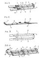
- FIG. 1 to 3 A first embodiment of a device according to the invention is illustrated in Figures 1 to 3, where it is shown mounted on a pair of skis 5.
- the sole 4 consists of a flexible band whose lower face has good sliding qualities as to its surface condition and its coefficient of friction on snow. It is secured at its front end to a first rigid member 1, profiled externally in the shape of a spatula and into which the tips 6 of the skis come to fit together. It is also secured at its rear end to a second rigid member 3 , capable of being fixed to the skis 5 by interlocking from above on the heels of the latter behind the bindings 7 of shoes.
- This second rigid member 3 is provided with an adjustment device 13, for example with a screw, cooperating with a fixed part of the skis 5, for example a location of the bindings 7, intended to adjust the position of the rigid member 3 on the skis 5 to ensure for example by tensioning an optimal deployment of the sole 4 under the skis 5.
- Transversal stiffening elements or spacers 8 are from place to place secured, for example by bonding, to the upper face of the sole 4 They can advantageously be provided at their ends with springs 11 or with pivoting parts coming to bear on the upper surface of the skis 5 to perfect the securing of the device to the skis 5.
- the implementation of the device for producing a single sliding vehicle is as follows.
- the spatulas 6 of the skis 5 are fitted.
- the sole is unwound along the sliding surface of the skis 5, until it is placed on the skis 5 of the second rigid member 3.
- it is then tensioned by action on the adjustment device 13, ensuring that the stiffening spacers 8 are positioned correctly. Any springs 11 or pivoting parts are then placed in their positive bearing position on the upper surface of the skis 5.
- the tension of the sole 4 between the rigid front 1 and rear 3 members in conjunction with the action of the springs or support pieces 11 ensures good positioning of this sole under the skis 5 to produce a continuous, homogeneous sliding surface, without wrinkles, blisters or other surface irregularities.
- the sole 4 on its face bearing on the sliding surface of the skis 5 will advantageously be provided with a permanent layer of adhesive material ensuring excellent bonding while allowing, after use, easy takeoff without damaging this sole 4 , as it is known for modern seal skins.
- this plating of the sole 4 can not only be maintained, but improved by the contact pressure of the snow.
- the device described can adapt perfectly and indifferently to any length and type of ski: piste, background, hike ... and allows the creation of a monoski, a snowboard , or even a sled depending on the circumstances and the temporary wishes of the user.
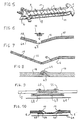
- FIG. 4 illustrates a variant of the previous embodiment in which the sole 4 extends beyond the end of the heels of the skis, forms a half-loop around a rigid return member 2 in which, for example, the heels of the skis, and ends with a tension strap 17 provided with a member 9 for securing and adjusting tension of the usual type coming to cooperate with the second rigid member 3 already mentioned and shaped for this function, and fixed to the skis 5 of any appropriate way (to the fastening 7, to the possible brake, or other body).
- recesses for the heels of the skis of the return member 2 may advantageously have a shape with a decreasing section towards the rear to receive any width of skis.
- FIG. 5 another embodiment of the invention is illustrated.
- the sole 4 is made up, apart from the anterior 1 and posterior 3 rigid members, of a succession of rigid elements or plates 18, articulated to each other in the longitudinal direction and playing both the role of the spacers 8 of the previous case with their support members 11 on the upper surface of the skis and, in the deployed state, forming by their lower face the sliding surface of the sole 4.
- the articulation between these successive elements 18 can be done, as illustrated in FIG. 6, by the elasticity of a very flexible sliding skin 41, glued on elements 18, and allowing their easy folding. From place to place, a larger gap 45 can be left between two successive elements 18 to allow accordion folding, a removable element of appropriate shape and advantageously provided with support members 11 on the upper face of the skis, coming after deployment ensure the mechanical continuity of the sole.
- FIG. 7 another type of articulation of the rigid elements 18 is schematically represented. This articulation is done by conventional hinges 46, placed alternately in the upper part and in the lower part of the elements 18 to allow easy accordion folding. These elements 18 already have on the underside the necessary qualities of sliding on snow. Otherwise, an adhesive sliding skin can always be added before use, as is usual with the usual seal skins.
- the elements 18 can also be, as shown in FIG. 8, discrete detached elements coming to nest successively in each other by complementary shapes 47, 48, the problem of the sliding surface being solved in an identical manner to the previous case.
- FIG. 9 an exploded cross-section is shown, an embodiment of one of the elements 18 corresponding to FIGS. 5 to 8.
- the element comprises a rigid core 40 corresponding to the thickness of the skis 5 and to their spacing, and carrying support members 11 on the skis 5.
- This core 40 is made integral with a larger plate 43 on which the lower face of the skis 5 is supported.
- This plate 43 can serve as a sliding surface but advantageously it will be coated with a flexible sole 42 ensuring this role and which may, if necessary, after assembly, be itself coated with a sliding skin 41, as already mentioned.
- FIG. 10 an exploded cross-section is shown, an exemplary embodiment of a type of removable element 18.
- the preceding core 40 constitutes a single piece with the support members 11 on the skis 5 in the form of leaf springs fixed on the plate 43.
- This plate 43 carries means 44 for defining the spacing of the skis and receives, if necessary, as previously mentioned, a sliding skin 41 removable and adhesive after mounting .
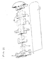
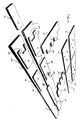
- FIG. 11 Such an exemplary embodiment of a device according to the invention is illustrated in exploded perspective in FIG. 11. It essentially consists of discrete discrete successive elements 18, positively fitting into each other, unlike of the overlap of FIG. 8.
- the rigid anterior 1 and posterior 3 terminal members have the female and male shapes allowing an interlocking which will ensure excellent cohesion of the device assembled for use.
- FIG. 11 is particularly explicit in this regard, and it is not useful to make other developments for the understanding of a person skilled in the art.
- the elements 18 are drilled in the longitudinal direction of at least one longitudinal central channel (this could also be two lateral longitudinal channels) to allow the passage of a tension member, for example a strap or a cable 17 anchored in the rigid front end member 1 and coming to be subjected after return to the rigid rear end member 3 by a tension adjustment device 9 which may be of the type already mentioned with reference to the device in FIG. 4.
- a tension member for example a strap or a cable 17 anchored in the rigid front end member 1 and coming to be subjected after return to the rigid rear end member 3 by a tension adjustment device 9 which may be of the type already mentioned with reference to the device in FIG. 4.
- a tension adjustment device 9 which may be of the type already mentioned with reference to the device in FIG. 4.
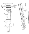
- Figures 12 to 14 relate to another embodiment of a device according to the present invention having in particular greater lightness.
- the sole 4 is constituted by a flexible strip, one end of which, called the front end, is integral with the first rigid member 1 externally shaped in the shape of a spatula and into which the spatulas of the skis 5 fit together.
- This front end of the sole 4 comprises a flexible plate 104 which is made integral with this sole by any known means, and which comprises a bar 105 cooperating with a recess 106 formed in the rigid part 1: once in the recess 106, the sole 4 is integral with this rigid part 1. This end is wider than the rest of the sole 4 so as to be able to rest on the surfaces of the skis 5.
- the width of the sole 4, beyond the flexible plate 104, is substantially equal to the space separating the two skis 5: it passes over a plate 107 located on the skis 5 near their tip, then under the second rigid member designated as a whole by the reference 3.
- This second rigid member 3 is, in this embodiment, located on the skis 5 where the shoe bindings will be placed. It comprises, firstly, two pairs 108 and 109 of bases each comprising a recess 110, secondly, two coupling bars 111 comprising pins 112 cooperating with the recesses 110 and the space 113 between the bases of a same pair, and thirdly two pairs of cover plates 114 and 115 fixed on each pair of base: these cover plates constitute a continuous sole.
- the second rigid member 3 comprises two reinforcing plates 116 arranged between each pair of bases 108 and 109: they help to maintain the space between the two skis 5.
- This fixing can be achieved by cooperation between holes 118 made in this rear end 115 with a stud 119 located on this bar.
- This rear end of the sole 4 can also be fixed by clipping or by any other equivalent means.
- the device according to the invention in one embodiment or the other, or by combining them according to his choice, makes it possible to compose from classic downhill, cross-country or touring skis, a new snow-making instrument such as a monoski, snowboard or even a sled.
Landscapes
- Fittings On The Vehicle Exterior For Carrying Loads, And Devices For Holding Or Mounting Articles (AREA)
Applications Claiming Priority (2)
| Application Number | Priority Date | Filing Date | Title |
|---|---|---|---|
| FR8916071A FR2654947B1 (fr) | 1989-11-29 | 1989-11-29 | Dispositif pour solidariser deux skis en constitutant une surface de glissement unique. |
| FR8916071 | 1989-11-29 |
Publications (1)
| Publication Number | Publication Date |
|---|---|
| EP0430805A1 true EP0430805A1 (de) | 1991-06-05 |
Family
ID=9388174
Family Applications (1)
| Application Number | Title | Priority Date | Filing Date |
|---|---|---|---|
| EP90403382A Withdrawn EP0430805A1 (de) | 1989-11-29 | 1990-11-29 | Vorrichtung zur Verbindung zweier Skier mittels einer Gleitfläche |
Country Status (2)
| Country | Link |
|---|---|
| EP (1) | EP0430805A1 (de) |
| FR (1) | FR2654947B1 (de) |
Cited By (3)
| Publication number | Priority date | Publication date | Assignee | Title |
|---|---|---|---|---|
| US5551728A (en) * | 1993-07-23 | 1996-09-03 | Silvretta-Sherpas Sportartikel Gmbh | Gliding board |
| US5649722A (en) * | 1995-01-30 | 1997-07-22 | Champlin; Jon F. | Convertible snowboard/skis |
| EP1952854A1 (de) * | 2007-02-02 | 2008-08-06 | ATOMIC Austria GmbH | Schi oder Snowboard mit einem Mittel zur Beeinflussung seiner Geometrie sowie Verfahren zu dessen Herstellung |
Citations (5)
| Publication number | Priority date | Publication date | Assignee | Title |
|---|---|---|---|---|
| AT340812B (de) * | 1976-03-24 | 1978-01-10 | Richard Thurnbichler | Schiartiges sportgerat |
| US4275904A (en) * | 1978-07-21 | 1981-06-30 | Pedersen Industries Ltd. | Mononose conversion for twinskis |
| NL8400572A (nl) * | 1984-02-23 | 1985-09-16 | Kees Radius | Monoski. |
| FR2564000A1 (fr) * | 1984-05-14 | 1985-11-15 | Roche Christian | Skis alpins transformables en monoski |
| FR2579475A1 (fr) * | 1985-04-02 | 1986-10-03 | Haupt Jean Francois | Dispositif pour la transformation d'une paire de skis en monoski |
-
1989
- 1989-11-29 FR FR8916071A patent/FR2654947B1/fr not_active Expired - Lifetime
-
1990
- 1990-11-29 EP EP90403382A patent/EP0430805A1/de not_active Withdrawn
Patent Citations (5)
| Publication number | Priority date | Publication date | Assignee | Title |
|---|---|---|---|---|
| AT340812B (de) * | 1976-03-24 | 1978-01-10 | Richard Thurnbichler | Schiartiges sportgerat |
| US4275904A (en) * | 1978-07-21 | 1981-06-30 | Pedersen Industries Ltd. | Mononose conversion for twinskis |
| NL8400572A (nl) * | 1984-02-23 | 1985-09-16 | Kees Radius | Monoski. |
| FR2564000A1 (fr) * | 1984-05-14 | 1985-11-15 | Roche Christian | Skis alpins transformables en monoski |
| FR2579475A1 (fr) * | 1985-04-02 | 1986-10-03 | Haupt Jean Francois | Dispositif pour la transformation d'une paire de skis en monoski |
Cited By (5)
| Publication number | Priority date | Publication date | Assignee | Title |
|---|---|---|---|---|
| US5551728A (en) * | 1993-07-23 | 1996-09-03 | Silvretta-Sherpas Sportartikel Gmbh | Gliding board |
| US5649722A (en) * | 1995-01-30 | 1997-07-22 | Champlin; Jon F. | Convertible snowboard/skis |
| EP1952854A1 (de) * | 2007-02-02 | 2008-08-06 | ATOMIC Austria GmbH | Schi oder Snowboard mit einem Mittel zur Beeinflussung seiner Geometrie sowie Verfahren zu dessen Herstellung |
| AT504801B1 (de) * | 2007-02-02 | 2009-05-15 | Atomic Austria Gmbh | Schi oder snowboard mit einem mittel zur beeinflussung dessen geometrie sowie verfahren zu dessen herstellung |
| US7900950B2 (en) | 2007-02-02 | 2011-03-08 | Atomic Austria Gmbh | Ski or snowboard with a means for influencing its geometry and a method of producing it |
Also Published As
| Publication number | Publication date |
|---|---|
| FR2654947B1 (fr) | 1992-04-03 |
| FR2654947A1 (fr) | 1991-05-31 |
Similar Documents
| Publication | Publication Date | Title |
|---|---|---|
| EP0510308B1 (de) | Dämpfungsvorrichtung für Skier | |
| EP0740908B1 (de) | Schuh zum Betreiben eines Wintersports | |
| FR2734490A1 (fr) | Planche de glisse sur neige comportant une plateforme de reception et de surelevation des fixations de la chaussure | |
| FR2734489A1 (fr) | Planche de glisse sur neige "a demi-coque", pourvue de chants de support de la coque | |
| FR2713052A1 (fr) | Chausson intérieur pour chaussure de sport. | |
| EP0473898B1 (de) | Langlaufski, insbesondere für die Praxis des abwechselnden Schrittes | |
| WO1996041547A1 (fr) | Chaussure destinee a la pratique d'un sport de glisse presentant un axe amovible | |
| CH664264A5 (fr) | Chaussure de ski. | |
| FR2641196A1 (fr) | Procede de montage rapide d'un dispositif de fixation d'une chaussure a un ski, et notamment d'un dispositif de fixation pour ski de fond, ski et dispositif de fixation pour la mise en oeuvre d'un tel procede de montage | |
| FR2926735A1 (fr) | Ski alpin avec moyens de reglage | |
| FR2768938A1 (fr) | Raquette a neige | |
| FR2744032A1 (fr) | Dispositif de retenue d'une chaussure sur une raquette a neige | |
| FR2657533A1 (fr) | Ski de fond pour patinage. | |
| FR2654947A1 (fr) | Dispositif pour solidariser deux skis en constitutant une surface de glissement unique. | |
| EP1327467A1 (de) | Vorrichtung zum Befestigen eines Schuhs auf einem Sportgerät | |
| CA2209772A1 (fr) | Chaussure de sport | |
| FR2611345A1 (fr) | Monoski separable en deux elements ou planches independants | |
| FR2726193A1 (fr) | Engin de glisse sur neige, tel que ski alpin, ski de fond, monoski, surf | |
| EP0648439B1 (de) | Schischuh | |
| FR3019754A1 (fr) | Dispositif anti-recul pour la pratique du ski de randonnee | |
| FR2662092A1 (fr) | Ski. | |
| FR2809634A1 (fr) | Dispositif de rehaussement destine a etre monte sur une planche de glisse | |
| CA2575333A1 (fr) | Dispositif retenue d'une chaussure sur une raquette a neige | |
| CA2215573A1 (fr) | Chaussure de sport comportant des moyens d'energisation | |
| FR3099346A1 (fr) | Chaussure de sport apte à coopérer avec un dispositif de fixation fixé à une planche de glisse |
Legal Events
| Date | Code | Title | Description |
|---|---|---|---|
| PUAI | Public reference made under article 153(3) epc to a published international application that has entered the european phase |
Free format text: ORIGINAL CODE: 0009012 |
|
| AK | Designated contracting states |
Kind code of ref document: A1 Designated state(s): AT CH DE ES FR IT LI SE |
|
| 17P | Request for examination filed |
Effective date: 19911227 |
|
| 17Q | First examination report despatched |
Effective date: 19930422 |
|
| STAA | Information on the status of an ep patent application or granted ep patent |
Free format text: STATUS: THE APPLICATION IS DEEMED TO BE WITHDRAWN |
|
| 18D | Application deemed to be withdrawn |
Effective date: 19941101 |