EP0430852A1 - Ailette avec générateur de tourbillon - Google Patents
Ailette avec générateur de tourbillon Download PDFInfo
- Publication number
- EP0430852A1 EP0430852A1 EP90630191A EP90630191A EP0430852A1 EP 0430852 A1 EP0430852 A1 EP 0430852A1 EP 90630191 A EP90630191 A EP 90630191A EP 90630191 A EP90630191 A EP 90630191A EP 0430852 A1 EP0430852 A1 EP 0430852A1
- Authority
- EP
- European Patent Office
- Prior art keywords
- fin
- vortex generator
- plate fin
- embossed
- enhanced
- Prior art date
- Legal status (The legal status is an assumption and is not a legal conclusion. Google has not performed a legal analysis and makes no representation as to the accuracy of the status listed.)
- Withdrawn
Links
- 239000012530 fluid Substances 0.000 claims abstract description 25
- 230000002708 enhancing effect Effects 0.000 claims description 2
- 238000011144 upstream manufacturing Methods 0.000 claims description 2
- 238000010008 shearing Methods 0.000 description 4
- 230000007423 decrease Effects 0.000 description 3
- 230000001965 increasing effect Effects 0.000 description 3
- 238000004519 manufacturing process Methods 0.000 description 3
- 238000004080 punching Methods 0.000 description 3
- 238000004378 air conditioning Methods 0.000 description 2
- 239000004020 conductor Substances 0.000 description 2
- 238000010586 diagram Methods 0.000 description 2
- 238000010438 heat treatment Methods 0.000 description 2
- 239000000463 material Substances 0.000 description 2
- 239000003507 refrigerant Substances 0.000 description 2
- 238000005057 refrigeration Methods 0.000 description 2
- 238000000926 separation method Methods 0.000 description 2
- 230000008719 thickening Effects 0.000 description 2
- 239000002699 waste material Substances 0.000 description 2
- XAGFODPZIPBFFR-UHFFFAOYSA-N aluminium Chemical compound [Al] XAGFODPZIPBFFR-UHFFFAOYSA-N 0.000 description 1
- 229910052782 aluminium Inorganic materials 0.000 description 1
- 238000005219 brazing Methods 0.000 description 1
- 239000002131 composite material Substances 0.000 description 1
- 230000006835 compression Effects 0.000 description 1
- 238000007906 compression Methods 0.000 description 1
- 238000001816 cooling Methods 0.000 description 1
- 239000012809 cooling fluid Substances 0.000 description 1
- 238000001704 evaporation Methods 0.000 description 1
- 239000012634 fragment Substances 0.000 description 1
- 239000007788 liquid Substances 0.000 description 1
- 238000012986 modification Methods 0.000 description 1
- 230000004048 modification Effects 0.000 description 1
- 238000009740 moulding (composite fabrication) Methods 0.000 description 1
- 230000002688 persistence Effects 0.000 description 1
- 230000021715 photosynthesis, light harvesting Effects 0.000 description 1
- 238000002360 preparation method Methods 0.000 description 1
- 238000005476 soldering Methods 0.000 description 1
- 238000006467 substitution reaction Methods 0.000 description 1
- XLYOFNOQVPJJNP-UHFFFAOYSA-N water Substances O XLYOFNOQVPJJNP-UHFFFAOYSA-N 0.000 description 1
Images


Classifications
-
- F—MECHANICAL ENGINEERING; LIGHTING; HEATING; WEAPONS; BLASTING
- F28—HEAT EXCHANGE IN GENERAL
- F28F—DETAILS OF HEAT-EXCHANGE AND HEAT-TRANSFER APPARATUS, OF GENERAL APPLICATION
- F28F3/00—Plate-like or laminated elements; Assemblies of plate-like or laminated elements
- F28F3/02—Elements or assemblies thereof with means for increasing heat-transfer area, e.g. with fins, with recesses, with corrugations
-
- F—MECHANICAL ENGINEERING; LIGHTING; HEATING; WEAPONS; BLASTING
- F28—HEAT EXCHANGE IN GENERAL
- F28F—DETAILS OF HEAT-EXCHANGE AND HEAT-TRANSFER APPARATUS, OF GENERAL APPLICATION
- F28F1/00—Tubular elements; Assemblies of tubular elements
- F28F1/10—Tubular elements and assemblies thereof with means for increasing heat-transfer area, e.g. with fins, with projections, with recesses
- F28F1/12—Tubular elements and assemblies thereof with means for increasing heat-transfer area, e.g. with fins, with projections, with recesses the means being only outside the tubular element
- F28F1/24—Tubular elements and assemblies thereof with means for increasing heat-transfer area, e.g. with fins, with projections, with recesses the means being only outside the tubular element and extending transversely
- F28F1/32—Tubular elements and assemblies thereof with means for increasing heat-transfer area, e.g. with fins, with projections, with recesses the means being only outside the tubular element and extending transversely the means having portions engaging further tubular elements
- F28F1/325—Fins with openings
Definitions
- the present invention relates generally to heat exchangers, and more particularly to finned tube heat exchanger coils having sine-wave like plate fins including embossed vortex generating enhancements.
- Plate fins utilized in the air conditioning and refrigeration industry are normally manufactured by progressively enhancing a coil of plate fin stock by a shearing operation whereby open enhancements are formed on the surface of the fin stock. After the open enhancements are formed, the fin stock is cut to the desired length. The fins are then collected in the proper orientation and number in preparation for forming a coil. Previously formed hairpin tubes are then inserted through openings within the fins and thereafter expanded to form mechanical and thermal connections between the tubes and fins. The open ends of the hairpin tubes are fluidly connected by way of U-shaped return bends, and subsequently the return bends are soldered or brazed in place.
- the plate fins are typically manufactured in a die with forming, punching or shearing pins to form the fin shape, the open surface enhancements on the fin, and the openings through which tubular members are inserted.
- prior art fins are provided with a variety of surface variations or enhancements to disrupt the boundary layer and to improve the transfer of heat energy between the fluid passing through the tubular members and the fluid passing over the plate fin surfaces.
- These prior art enhanced fins are generally either enhanced flat fins or convoluted fins.
- Flat fins and convoluted fins are generally enhanced by punching or shearing raised lances, louvers, or ramp and delta wings therein.
- a raised lance is defined as an elongated portion of fin formed by two parallel slits whereby the material between the parallel slits is raised or displaced from the mid-plane of the fin.
- a louver is defined as an elongated portion of fin formed by one or two parallel slits whereby the material adjacent to a singular slit, or between parallel slits, is rotated about the mid-plane of the fin to a prescribed angle.
- a ramp or delta wing is defined as a portion of a fin having one side length connected to the fin in a direction generally perpendicular to the direction of fluid flow over the wing while the remaining sides are slit and raised from the surface of the fin. Typical of the previous plate fin heat exchangers utilizing enhancements are U.S.
- lanced, louvered, and raised winged plate fins may be difficult and costly to manufacture, due to the complex manufacturing problems associated with numerous, small punching stations which are necessary to shear the fin stock to make the enhancements. Still further, the shearing operation results in waste material in the form of scrap fragments which can render the forming die inoperable.
- an enhanced plate fin having a sine-wave like pattern in cross-section having rows of embossed vortex generators at the peaks and troughs of the sin-wave or at a predetermined distance downstream of the peaks and troughs along their longitudinal length.
- the embossed vortex generators are generally of a height in the range between 1/4 and 1/2 of the distance between adjacent fins in a coil to prevent boundary layer thickening and separation, since the vortices generated by those embossed elements are of the same proportion as the embossments themselves.
- the rows of vortex generators are alternately embossed on opposite surfaces of the fin to decrease the thermal resistance between adjacent fins.
- Plate fin heat exchangers are generally used in conventional direct expansion vapor compression refrigeration systems.
- the compressor compresses gaseous refrigerant, often R-22, which is then circulated through a condenser where it is cooled and liquified and then through an expanding control device to the low pressure side of the system where it s evaporated in another heat exchanger as it absorbs heat from the fluid to be cooled and changes phase from a partial liquid and partial vapor to a superheated vapor.
- the superheated vapor then flows the compressor to complete the cycle.
- a plate fin heat exchanger is assembled by stacking a plurality of parallel fins, and inserting a plurality of hair pin tubes through the fins and mechanically expanding the tubes to make physical contract with each fin.
- the heat transfer characteristics of the heat exchanger are largely determined by the heat transfer characteristics of the individual plate fins.
- Heat exchanger coil 10 comprises a plurality of spaced-apart fin plates 12, wherein each plate fin 12 has a plurality of holes 16 therein.
- Fin plates 12 may be any heat conductive material, e.g. aluminum. Fin plates 12 are maintained together by oppositely disposed tube sheets 18 having holes therethrough in axially alignment with holes 16.
- a plurality of hair pin tubes 20 are laced through selected pairs of holes 16 as illustrated and have their open ends joined together in fluid communication by return bends 22, which are secured to hair pin tubes 20 by soldering or brazing or the like.
- the hair pin tubes may be any heat conductive material, for example, cooper.
- a first fluid to be cooled or heated flows through hair pin tubes 20 and a cooling or heating fluid is then passed between fin sheets 12 and over tubes 20 in a direction indicated by arrow A. Heat energy is transferred from or to the first fluid through hair pin tubes 20 and plate fins 12 to or from the other fluid.
- the fluids may be different types, for example, the fluid flowing through tubes 20 can be refrigerant and the cooling fluid flowing between plate fins 12 and over the tubes 20 can be air.
- finned tube heat exchanger coil 10 is a staggered two-row coil since each plate fin 12 has two rows of staggered holes therein for receiving hair pin tubes 20.
- the present invention contemplates a heat exchanger coil of one or more rows of tubes and with holes 16 of one row in either staggered or in-line relation with the holes 16 of an adjacent row.
- the heat exchanger can be a single row heat exchanger or a composite heat exchanger made from a plurality of singe row heat exchangers.
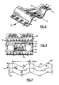
- FIG. 2-7 a portion of the multi-row plate fin 12 is illustrated having staggered rows of tube holes 16 with enhanced heat transfer sections 24 between respective adjacent pairs of holes 16.
- a fluid in the direction of arrow A, flows across the multi-row plate fin.
- Collars 14 are formed about holes 16 during fin manufacture for receiving tubes 20 therein and for properly spacing adjacent plate fins. In Figures 2-7 only the plate fin 12 is shown and the tubes that would normally pass through the collars 14 are omitted for simplicity.
- the plate fin 12 has a fluid flowing over the top side or upper surface 32 and over the bottom side or lower surface 34.
- the fluid flows over both of these surfaces in the same direction.
- the triangular shaped embossments 40, as shown in Figures 2-4, and the circular or dome shaped embossments 40′, as shown in figures 5-7, are formed in rows in a direction perpendicular to the flow "A".
- the embossments 40 and 40′ in adjacent rows are moved alternately away from the top surface 32 then the bottom surface 34 and generate counter rotating vortices as shown by arrows "a".
- the triangular shaped embossments 40 and circular shaped embossments 40′ are generally embossed in the plate fin in the range between 0 ⁇ and 1/4 ⁇ downstream in the flow direction of the longitudinal center-line (shown as line L) of the peaks 36 and troughs 38 thus generating vortices on both the upper and lower surfaces to energize the boundary layer fluid.
- One complete length of sine-wave like pattern is defined as Lambda ( ⁇ ).
- the off-center position of the embossed wings 40 downstream of the longitudinal center line (L) of the peaks 36 and troughs 38 is generally equal to the point of maximum pressure difference about the fin surface.
- the embossed wings 40 shown in Figs.
- the vortices that are generated by the embossments 40 and 40′ have been found to be of the same proportions as the embossments themselves and since efficiency can be increased by energizing the boundary layer fluid it is desirable to generate vortices of the same size order as the boundary layer and to direct them into the boundary layer.
- the range of the height ("h") of the embossments 40 and 40′ is in the preferred range between 1/4d and 1/2d.
- Fig. 8 is a diagram showing the dry performance relationship between the circular embossment 40′ and a split wavy-fin enhanced fin of the prior art, wherein the thermal resistance (RA) (m2° K/W) (HR-F-SQ. FT./BTU) and the pressure drop per tube rows (DP/NR) (kPa/row) (inches of water/row) are given as an ordinate and the air velocity (V) (m/sec-294°K standard air) (FT./MIN-70°F standard air) is given as an abscissa.
- RA thermal resistance
- DP/NR pressure drop per tube rows
- V air velocity
Landscapes
- Engineering & Computer Science (AREA)
- Physics & Mathematics (AREA)
- Thermal Sciences (AREA)
- Mechanical Engineering (AREA)
- General Engineering & Computer Science (AREA)
- Geometry (AREA)
- Heat-Exchange Devices With Radiators And Conduit Assemblies (AREA)
- Laminated Bodies (AREA)
Applications Claiming Priority (2)
| Application Number | Priority Date | Filing Date | Title |
|---|---|---|---|
| US07/441,026 US4984626A (en) | 1989-11-24 | 1989-11-24 | Embossed vortex generator enhanced plate fin |
| US441026 | 1989-11-24 |
Publications (1)
| Publication Number | Publication Date |
|---|---|
| EP0430852A1 true EP0430852A1 (fr) | 1991-06-05 |
Family
ID=23751196
Family Applications (1)
| Application Number | Title | Priority Date | Filing Date |
|---|---|---|---|
| EP90630191A Withdrawn EP0430852A1 (fr) | 1989-11-24 | 1990-11-08 | Ailette avec générateur de tourbillon |
Country Status (8)
| Country | Link |
|---|---|
| US (1) | US4984626A (fr) |
| EP (1) | EP0430852A1 (fr) |
| JP (1) | JPH03181796A (fr) |
| KR (1) | KR910010150A (fr) |
| AU (1) | AU6690390A (fr) |
| BR (1) | BR9005939A (fr) |
| CA (1) | CA2026549C (fr) |
| MX (1) | MX170099B (fr) |
Cited By (8)
| Publication number | Priority date | Publication date | Assignee | Title |
|---|---|---|---|---|
| FR2665521A1 (fr) * | 1990-08-03 | 1992-02-07 | American Standard Inc | Surface onduleuse perfectionnee de transfert de chaleur. |
| FR2818368A1 (fr) * | 2000-12-19 | 2002-06-21 | Denso Corp | Echangeur thermique a ailettes pour le refroidissement des gaz d'echappement d'un moteur a combustion |
| WO2002090857A1 (fr) * | 2001-05-04 | 2002-11-14 | Carrier Corporation | Evaporateur pour presentoir distributeur refrigere a temperature moyenne |
| WO2004025206A1 (fr) * | 2002-09-12 | 2004-03-25 | York International Corporation | Ailette d'echangeur thermique a crevees inclinees |
| US6789317B1 (en) * | 2003-06-17 | 2004-09-14 | Bechtel Bwxt Idaho, Llc | Finned tube with vortex generators for a heat exchanger |
| DE202004013882U1 (de) * | 2004-09-03 | 2006-01-12 | Autokühler GmbH & Co. KG | Wärmeübertragungsbauteil und damit hergestellter Wärmeaustauscher |
| US7004242B2 (en) | 2004-06-14 | 2006-02-28 | Advanced Heat Transfer, Llc | Enhanced heat exchanger apparatus and method |
| WO2021098024A1 (fr) * | 2019-11-21 | 2021-05-27 | 广州高澜节能技术股份有限公司 | Ailette perfectionnée d'échange de chaleur pour refroidisseur d'air du type à pièce de manchon |
Families Citing this family (61)
| Publication number | Priority date | Publication date | Assignee | Title |
|---|---|---|---|---|
| US5628362A (en) * | 1993-12-22 | 1997-05-13 | Goldstar Co., Ltd. | Fin-tube type heat exchanger |
| DE4404357C2 (de) * | 1994-02-11 | 1998-05-20 | Wieland Werke Ag | Wärmeaustauschrohr zum Kondensieren von Dampf |
| KR960011914U (ko) * | 1994-09-16 | 1996-04-15 | 열교환기 | |
| US5797448A (en) * | 1996-10-22 | 1998-08-25 | Modine Manufacturing Co. | Humped plate fin heat exchanger |
| JP4482991B2 (ja) * | 1999-12-14 | 2010-06-16 | 株式会社デンソー | 複式熱交換器 |
| US6729388B2 (en) * | 2000-01-28 | 2004-05-04 | Behr Gmbh & Co. | Charge air cooler, especially for motor vehicles |
| US6644388B1 (en) | 2000-10-27 | 2003-11-11 | Alcoa Inc. | Micro-textured heat transfer surfaces |
| US6536255B2 (en) | 2000-12-07 | 2003-03-25 | Brazeway, Inc. | Multivoid heat exchanger tubing with ultra small voids and method for making the tubing |
| CA2391077A1 (fr) | 2001-06-28 | 2002-12-28 | York International Corporation | Ailette a plaque en v sureleve pour echangeur thermique et methode de fabrication connexe |
| JP3912080B2 (ja) * | 2001-07-25 | 2007-05-09 | 株式会社デンソー | 排気熱交換装置 |
| US7337831B2 (en) * | 2001-08-10 | 2008-03-04 | Yokohama Tlo Company Ltd. | Heat transfer device |
| KR100407478B1 (ko) * | 2001-10-17 | 2003-12-01 | (주)코맨텍 | 열교환용 방열기 |
| US6862183B2 (en) * | 2001-10-29 | 2005-03-01 | Intel Corporation | Composite fins for heat sinks |
| US6636423B2 (en) * | 2001-10-29 | 2003-10-21 | Intel Corporation | Composite fins for heat sinks |
| US6578627B1 (en) * | 2001-12-28 | 2003-06-17 | Industrial Technology Research Institute | Pattern with ribbed vortex generator |
| US20030131976A1 (en) * | 2002-01-11 | 2003-07-17 | Krause Paul E. | Gravity fed heat exchanger |
| US6598295B1 (en) | 2002-03-07 | 2003-07-29 | Brazeway, Inc. | Plate-fin and tube heat exchanger with a dog-bone and serpentine tube insertion method |
| TW587902U (en) * | 2002-07-26 | 2004-05-11 | Hon Hai Prec Ind Co Ltd | Heat sink |
| US7410483B2 (en) * | 2003-05-23 | 2008-08-12 | Novare Surgical Systems, Inc. | Hand-actuated device for remote manipulation of a grasping tool |
| US20060169019A1 (en) * | 2003-07-10 | 2006-08-03 | Kutscher Charles F | Tabbed transfer fins for air-cooled heat exchanger |
| US6907919B2 (en) * | 2003-07-11 | 2005-06-21 | Visteon Global Technologies, Inc. | Heat exchanger louver fin |
| DE20312313U1 (de) * | 2003-08-09 | 2004-12-16 | Eichenauer Heizelemente Gmbh & Co. Kg | Vorrichtung zum Erwärmen von Gasströmen |
| TWM263734U (en) * | 2004-05-14 | 2005-05-01 | Hung-Yi Lin | Cooling fin with wind deflecting leading edge |
| US20070144711A1 (en) * | 2004-11-19 | 2007-06-28 | Eco Lean Research & Development A/S | Heat exchanger plate and plate heat exchanger comprising such plates |
| DE202004020294U1 (de) * | 2004-12-29 | 2006-05-11 | Autokühler GmbH & Co. KG | Wärmeaustauschelement und damit hergestellter Wärmeaustauscher |
| JP4028591B2 (ja) * | 2006-04-21 | 2007-12-26 | 松下電器産業株式会社 | 伝熱フィンおよびフィンチューブ型熱交換器 |
| US20070246202A1 (en) * | 2006-04-25 | 2007-10-25 | Yu Wen F | Louvered fin for heat exchanger |
| US20080017350A1 (en) * | 2006-07-21 | 2008-01-24 | Foxconn Technology Co., Ltd. | Heat sink |
| US7568518B2 (en) * | 2006-07-21 | 2009-08-04 | Furui Precise Component (Kunshan) Co., Ltd. | Heat sink |
| US7743821B2 (en) * | 2006-07-26 | 2010-06-29 | General Electric Company | Air cooled heat exchanger with enhanced heat transfer coefficient fins |
| JP4169079B2 (ja) * | 2006-10-02 | 2008-10-22 | ダイキン工業株式会社 | フィンチューブ型熱交換器 |
| US7845396B2 (en) * | 2007-07-24 | 2010-12-07 | Asia Vital Components Co., Ltd. | Heat dissipation device with coarse surface capable of intensifying heat transfer |
| JP5536312B2 (ja) * | 2008-04-23 | 2014-07-02 | シャープ株式会社 | 熱交換システム |
| US20100212876A1 (en) * | 2009-02-23 | 2010-08-26 | Trane International Inc. | Heat Exchanger |
| US20100252247A1 (en) * | 2009-04-03 | 2010-10-07 | Smith Iii Richard S | Heat Transfer Device And Method |
| CN102083296A (zh) * | 2009-11-27 | 2011-06-01 | 鸿富锦精密工业(深圳)有限公司 | 散热装置 |
| US8875780B2 (en) * | 2010-01-15 | 2014-11-04 | Rigidized Metals Corporation | Methods of forming enhanced-surface walls for use in apparatae for performing a process, enhanced-surface walls, and apparatae incorporating same |
| US20110308228A1 (en) * | 2010-06-18 | 2011-12-22 | General Electric Company | Fin and Tube Heat Exchanger |
| US20120012284A1 (en) * | 2010-07-13 | 2012-01-19 | Alcatel-Lucent Usa Inc. | heat sink with staggered heat exchange elements |
| CN102297624A (zh) * | 2011-07-14 | 2011-12-28 | 许昌怡家电器有限公司 | 一种强化换热翅片 |
| KR101299072B1 (ko) * | 2011-11-29 | 2013-08-27 | 주식회사 코렌스 | 웨이브 핀 |
| JP2014089019A (ja) * | 2012-10-31 | 2014-05-15 | Panasonic Corp | フィンチューブ熱交換器及びそれを備えた冷凍サイクル装置 |
| CN102954727A (zh) * | 2012-11-26 | 2013-03-06 | 海信科龙电器股份有限公司 | 一种换热器的换热片 |
| RU2642203C2 (ru) * | 2013-01-25 | 2018-01-24 | Питер ИРЛЕНД | Способ и система аэро/гидродинамического регулирования потока ньютоновской текучей среды в радиальной турбомашине |
| WO2014138952A1 (fr) | 2013-03-15 | 2014-09-18 | Dana Canada Corporation | Surface de transfert thermique avec languettes imbriquées |
| CN105339752B (zh) * | 2013-06-27 | 2018-09-28 | 达纳加拿大公司 | 具有性能增强部件的流体管道以及包括所述流体管道的装置 |
| CN103438746B (zh) * | 2013-08-14 | 2015-07-01 | 西安交通大学 | 一种用于余热回收的椭圆管h型翅片换热器 |
| WO2016075666A1 (fr) * | 2014-11-14 | 2016-05-19 | Stefani S.P.A. | Ailette pour un bloc à ailettes pour échangeurs de chaleur et échangeur de chaleur |
| CN104807362A (zh) * | 2015-04-22 | 2015-07-29 | 哈尔滨工程大学 | 一种高效板翅式换热器翅片 |
| US10823513B2 (en) | 2016-02-04 | 2020-11-03 | Evapco, Inc. | Arrowhead fin for heat exchange tubing |
| EP3411649B1 (fr) * | 2016-02-04 | 2021-10-13 | Evapco, Inc. | Ailette à forme de pointe de flèche pour tubulure d'échange de chaleur |
| ES2840726T3 (es) * | 2016-07-01 | 2021-07-07 | Mitsubishi Electric Corp | Intercambiador de calor y dispositivo de ciclo de refrigeración dotado de intercambiador de calor |
| CN106643264B (zh) * | 2016-12-27 | 2018-09-07 | 南昌工程学院 | 一种多孔圆筒型涡翅片 |
| RU2634167C1 (ru) * | 2016-12-30 | 2017-10-24 | Общество с ограниченной ответственностью "НИЦ супер-ЭВМ и нейрокомпьютеров" | Радиатор |
| US11454448B2 (en) | 2017-11-27 | 2022-09-27 | Dana Canada Corporation | Enhanced heat transfer surface |
| US11774187B2 (en) * | 2018-04-19 | 2023-10-03 | Kyungdong Navien Co., Ltd. | Heat transfer fin of fin-tube type heat exchanger |
| CN110726323A (zh) * | 2019-11-19 | 2020-01-24 | 广东美的暖通设备有限公司 | 用于换热器的散热翅片、换热器和制冷设备 |
| CN116772640A (zh) * | 2022-03-15 | 2023-09-19 | 开利公司 | 高性能锯齿正弦波翅片构造 |
| JP2024157853A (ja) * | 2023-04-26 | 2024-11-08 | 株式会社小松製作所 | 熱交換器 |
| CN116697783B (zh) * | 2023-05-29 | 2025-10-28 | 山东建筑大学 | 一种具有仿生翼型翅片的印刷电路板换热器芯体 |
| CN121531686B (zh) * | 2026-01-14 | 2026-04-03 | 苏州元脑智能科技有限公司 | 散热装置、散热系统及电子设备 |
Citations (2)
| Publication number | Priority date | Publication date | Assignee | Title |
|---|---|---|---|---|
| US4817709A (en) * | 1987-12-02 | 1989-04-04 | Carrier Corporation | Ramp wing enhanced plate fin |
| EP0325553A1 (fr) * | 1988-01-11 | 1989-07-26 | Carrier Corporation | Ailette ondulée |
Family Cites Families (10)
| Publication number | Priority date | Publication date | Assignee | Title |
|---|---|---|---|---|
| US1416570A (en) * | 1918-01-22 | 1922-05-16 | Arthur B Modine | Radiator core |
| US1557467A (en) * | 1920-05-10 | 1925-10-13 | Arthur B Modine | Radiator |
| US1453250A (en) * | 1922-08-26 | 1923-04-24 | C G Haubold Aktien Ges | Heat-exchanging apparatus |
| US1575864A (en) * | 1922-10-19 | 1926-03-09 | Mccord Radiator & Mfg Co | Automobile radiator core |
| US1927325A (en) * | 1931-10-12 | 1933-09-19 | Long Mfg Co Inc | Radiator fin construction |
| US1971842A (en) * | 1934-01-15 | 1934-08-28 | Young Radiator Co | Heat transfer device |
| US2217469A (en) * | 1940-03-09 | 1940-10-08 | Vulcan Radiator Co | Heat transfer unit |
| JPS5575190A (en) * | 1978-12-04 | 1980-06-06 | Matsushita Refrig Co | Heat-exchanger |
| NL8100334A (nl) * | 1980-01-28 | 1981-08-17 | Lummus Co | Buis met plaatvormige ribben en warmtewisselaar die met zulke ribben is uitgerust. |
| US4279298A (en) * | 1980-03-17 | 1981-07-21 | Borg-Warner Corporation | Heat exchanger with condensate blow-off suppressor |
-
1989
- 1989-11-24 US US07/441,026 patent/US4984626A/en not_active Expired - Fee Related
-
1990
- 1990-09-28 CA CA002026549A patent/CA2026549C/fr not_active Expired - Fee Related
- 1990-11-08 EP EP90630191A patent/EP0430852A1/fr not_active Withdrawn
- 1990-11-22 MX MX023422A patent/MX170099B/es unknown
- 1990-11-22 JP JP2320592A patent/JPH03181796A/ja active Pending
- 1990-11-23 BR BR909005939A patent/BR9005939A/pt not_active Application Discontinuation
- 1990-11-23 KR KR1019900019063A patent/KR910010150A/ko not_active Withdrawn
- 1990-11-23 AU AU66903/90A patent/AU6690390A/en not_active Abandoned
Patent Citations (2)
| Publication number | Priority date | Publication date | Assignee | Title |
|---|---|---|---|---|
| US4817709A (en) * | 1987-12-02 | 1989-04-04 | Carrier Corporation | Ramp wing enhanced plate fin |
| EP0325553A1 (fr) * | 1988-01-11 | 1989-07-26 | Carrier Corporation | Ailette ondulée |
Cited By (11)
| Publication number | Priority date | Publication date | Assignee | Title |
|---|---|---|---|---|
| FR2665521A1 (fr) * | 1990-08-03 | 1992-02-07 | American Standard Inc | Surface onduleuse perfectionnee de transfert de chaleur. |
| FR2818368A1 (fr) * | 2000-12-19 | 2002-06-21 | Denso Corp | Echangeur thermique a ailettes pour le refroidissement des gaz d'echappement d'un moteur a combustion |
| WO2002090857A1 (fr) * | 2001-05-04 | 2002-11-14 | Carrier Corporation | Evaporateur pour presentoir distributeur refrigere a temperature moyenne |
| AU2002254641B2 (en) * | 2001-05-04 | 2006-12-14 | Carrier Corporation | Evaporator for medium temperature refrigerated merchandiser |
| WO2004025206A1 (fr) * | 2002-09-12 | 2004-03-25 | York International Corporation | Ailette d'echangeur thermique a crevees inclinees |
| US6786274B2 (en) | 2002-09-12 | 2004-09-07 | York International Corporation | Heat exchanger fin having canted lances |
| US6789317B1 (en) * | 2003-06-17 | 2004-09-14 | Bechtel Bwxt Idaho, Llc | Finned tube with vortex generators for a heat exchanger |
| US6976301B2 (en) | 2003-06-17 | 2005-12-20 | Battelle Energy Alliance, Llc | Finned tube with vortex generators for a heat exchanger |
| US7004242B2 (en) | 2004-06-14 | 2006-02-28 | Advanced Heat Transfer, Llc | Enhanced heat exchanger apparatus and method |
| DE202004013882U1 (de) * | 2004-09-03 | 2006-01-12 | Autokühler GmbH & Co. KG | Wärmeübertragungsbauteil und damit hergestellter Wärmeaustauscher |
| WO2021098024A1 (fr) * | 2019-11-21 | 2021-05-27 | 广州高澜节能技术股份有限公司 | Ailette perfectionnée d'échange de chaleur pour refroidisseur d'air du type à pièce de manchon |
Also Published As
| Publication number | Publication date |
|---|---|
| US4984626A (en) | 1991-01-15 |
| MX170099B (es) | 1993-08-06 |
| CA2026549C (fr) | 1993-10-12 |
| BR9005939A (pt) | 1991-09-24 |
| KR910010150A (ko) | 1991-06-29 |
| JPH03181796A (ja) | 1991-08-07 |
| CA2026549A1 (fr) | 1991-05-25 |
| AU6690390A (en) | 1991-05-30 |
Similar Documents
| Publication | Publication Date | Title |
|---|---|---|
| US4984626A (en) | Embossed vortex generator enhanced plate fin | |
| US4787442A (en) | Delta wing and ramp wing enhanced plate fin | |
| US4817709A (en) | Ramp wing enhanced plate fin | |
| US4860822A (en) | Lanced sine-wave heat exchanger | |
| EP1231448B1 (fr) | Echangeur de chaleur | |
| US5056594A (en) | Wavy heat transfer surface | |
| US4691768A (en) | Lanced fin condenser for central air conditioner | |
| US5318112A (en) | Finned-duct heat exchanger | |
| EP0188314B1 (fr) | Procédé pour fixer un tube dans une ailette | |
| US3380518A (en) | Finned heat exchanger | |
| JPH0611280A (ja) | 蒸発器又は蒸発器兼凝縮器 | |
| EP0583851A2 (fr) | Echangeur de chaleur | |
| CA1269975A (fr) | Echangeur thermique | |
| CN109312991B (zh) | 热交换器及具备该热交换器的制冷循环装置 | |
| US11519679B2 (en) | Vortex-enhanced heat exchanger | |
| EP2315997B1 (fr) | Ailette d'echangeur de chaleur comprenant des persiennes | |
| EP0325553B1 (fr) | Ailette ondulée | |
| KR101572674B1 (ko) | 배수성이 향상된 방열핀을 이용한 열교환기 | |
| EP1664656B1 (fr) | Echangeur de chaleur avec ailette de refroidissement | |
| JPH11281279A (ja) | 熱交換器 | |
| US2999304A (en) | Method of manufacturing heat exchangers | |
| JPH07324884A (ja) | 熱交換器用コルゲート・フィン | |
| US3368261A (en) | Method of making heat exchangers | |
| WO2025158530A1 (fr) | Échangeur de chaleur et dispositif à cycle de réfrigération le comportant | |
| US3321014A (en) | Heat exchanger |
Legal Events
| Date | Code | Title | Description |
|---|---|---|---|
| PUAI | Public reference made under article 153(3) epc to a published international application that has entered the european phase |
Free format text: ORIGINAL CODE: 0009012 |
|
| AK | Designated contracting states |
Kind code of ref document: A1 Designated state(s): ES FR IT |
|
| 17P | Request for examination filed |
Effective date: 19910731 |
|
| 17Q | First examination report despatched |
Effective date: 19920629 |
|
| STAA | Information on the status of an ep patent application or granted ep patent |
Free format text: STATUS: THE APPLICATION IS DEEMED TO BE WITHDRAWN |
|
| 18D | Application deemed to be withdrawn |
Effective date: 19940917 |