EP0430854B1 - Multipiece eccentric shaft - Google Patents
Multipiece eccentric shaft Download PDFInfo
- Publication number
- EP0430854B1 EP0430854B1 EP90630199A EP90630199A EP0430854B1 EP 0430854 B1 EP0430854 B1 EP 0430854B1 EP 90630199 A EP90630199 A EP 90630199A EP 90630199 A EP90630199 A EP 90630199A EP 0430854 B1 EP0430854 B1 EP 0430854B1
- Authority
- EP
- European Patent Office
- Prior art keywords
- bearing cap
- drive shaft
- rotor shaft
- shaft
- scroll
- Prior art date
- Legal status (The legal status is an assumption and is not a legal conclusion. Google has not performed a legal analysis and makes no representation as to the accuracy of the status listed.)
- Expired - Lifetime
Links
Images

Classifications
-
- F—MECHANICAL ENGINEERING; LIGHTING; HEATING; WEAPONS; BLASTING
- F04—POSITIVE - DISPLACEMENT MACHINES FOR LIQUIDS; PUMPS FOR LIQUIDS OR ELASTIC FLUIDS
- F04C—ROTARY-PISTON, OR OSCILLATING-PISTON, POSITIVE-DISPLACEMENT MACHINES FOR LIQUIDS; ROTARY-PISTON, OR OSCILLATING-PISTON, POSITIVE-DISPLACEMENT PUMPS
- F04C18/00—Rotary-piston pumps specially adapted for elastic fluids
- F04C18/02—Rotary-piston pumps specially adapted for elastic fluids of arcuate-engagement type, i.e. with circular translatory movement of co-operating members, each member having the same number of teeth or tooth-equivalents
-
- F—MECHANICAL ENGINEERING; LIGHTING; HEATING; WEAPONS; BLASTING
- F04—POSITIVE - DISPLACEMENT MACHINES FOR LIQUIDS; PUMPS FOR LIQUIDS OR ELASTIC FLUIDS
- F04C—ROTARY-PISTON, OR OSCILLATING-PISTON, POSITIVE-DISPLACEMENT MACHINES FOR LIQUIDS; ROTARY-PISTON, OR OSCILLATING-PISTON, POSITIVE-DISPLACEMENT PUMPS
- F04C29/00—Component parts, details or accessories of pumps or pumping installations, not provided for in groups F04C18/00 - F04C28/00
- F04C29/02—Lubrication; Lubricant separation
- F04C29/023—Lubricant distribution through a hollow driving shaft
-
- F—MECHANICAL ENGINEERING; LIGHTING; HEATING; WEAPONS; BLASTING
- F04—POSITIVE - DISPLACEMENT MACHINES FOR LIQUIDS; PUMPS FOR LIQUIDS OR ELASTIC FLUIDS
- F04C—ROTARY-PISTON, OR OSCILLATING-PISTON, POSITIVE-DISPLACEMENT MACHINES FOR LIQUIDS; ROTARY-PISTON, OR OSCILLATING-PISTON, POSITIVE-DISPLACEMENT PUMPS
- F04C18/00—Rotary-piston pumps specially adapted for elastic fluids
- F04C18/02—Rotary-piston pumps specially adapted for elastic fluids of arcuate-engagement type, i.e. with circular translatory movement of co-operating members, each member having the same number of teeth or tooth-equivalents
- F04C18/0207—Rotary-piston pumps specially adapted for elastic fluids of arcuate-engagement type, i.e. with circular translatory movement of co-operating members, each member having the same number of teeth or tooth-equivalents both members having co-operating elements in spiral form
- F04C18/0215—Rotary-piston pumps specially adapted for elastic fluids of arcuate-engagement type, i.e. with circular translatory movement of co-operating members, each member having the same number of teeth or tooth-equivalents both members having co-operating elements in spiral form where only one member is moving
-
- F—MECHANICAL ENGINEERING; LIGHTING; HEATING; WEAPONS; BLASTING
- F04—POSITIVE - DISPLACEMENT MACHINES FOR LIQUIDS; PUMPS FOR LIQUIDS OR ELASTIC FLUIDS
- F04C—ROTARY-PISTON, OR OSCILLATING-PISTON, POSITIVE-DISPLACEMENT MACHINES FOR LIQUIDS; ROTARY-PISTON, OR OSCILLATING-PISTON, POSITIVE-DISPLACEMENT PUMPS
- F04C29/00—Component parts, details or accessories of pumps or pumping installations, not provided for in groups F04C18/00 - F04C28/00
- F04C29/0042—Driving elements, brakes, couplings, transmissions specially adapted for pumps
-
- F—MECHANICAL ENGINEERING; LIGHTING; HEATING; WEAPONS; BLASTING
- F04—POSITIVE - DISPLACEMENT MACHINES FOR LIQUIDS; PUMPS FOR LIQUIDS OR ELASTIC FLUIDS
- F04C—ROTARY-PISTON, OR OSCILLATING-PISTON, POSITIVE-DISPLACEMENT MACHINES FOR LIQUIDS; ROTARY-PISTON, OR OSCILLATING-PISTON, POSITIVE-DISPLACEMENT PUMPS
- F04C2220/00—Application
- F04C2220/40—Pumps with means for venting areas other than the working chamber, e.g. bearings, gear chambers, shaft seals
-
- F—MECHANICAL ENGINEERING; LIGHTING; HEATING; WEAPONS; BLASTING
- F04—POSITIVE - DISPLACEMENT MACHINES FOR LIQUIDS; PUMPS FOR LIQUIDS OR ELASTIC FLUIDS
- F04C—ROTARY-PISTON, OR OSCILLATING-PISTON, POSITIVE-DISPLACEMENT MACHINES FOR LIQUIDS; ROTARY-PISTON, OR OSCILLATING-PISTON, POSITIVE-DISPLACEMENT PUMPS
- F04C23/00—Combinations of two or more pumps, each being of rotary-piston or oscillating-piston type, specially adapted for elastic fluids; Pumping installations specially adapted for elastic fluids; Multi-stage pumps specially adapted for elastic fluids
- F04C23/008—Hermetic pumps
-
- F—MECHANICAL ENGINEERING; LIGHTING; HEATING; WEAPONS; BLASTING
- F16—ENGINEERING ELEMENTS AND UNITS; GENERAL MEASURES FOR PRODUCING AND MAINTAINING EFFECTIVE FUNCTIONING OF MACHINES OR INSTALLATIONS; THERMAL INSULATION IN GENERAL
- F16C—SHAFTS; FLEXIBLE SHAFTS; ELEMENTS OR CRANKSHAFT MECHANISMS; ROTARY BODIES OTHER THAN GEARING ELEMENTS; BEARINGS
- F16C2360/00—Engines or pumps
- F16C2360/42—Pumps with cylinders or pistons
-
- Y—GENERAL TAGGING OF NEW TECHNOLOGICAL DEVELOPMENTS; GENERAL TAGGING OF CROSS-SECTIONAL TECHNOLOGIES SPANNING OVER SEVERAL SECTIONS OF THE IPC; TECHNICAL SUBJECTS COVERED BY FORMER USPC CROSS-REFERENCE ART COLLECTIONS [XRACs] AND DIGESTS
- Y10—TECHNICAL SUBJECTS COVERED BY FORMER USPC
- Y10T—TECHNICAL SUBJECTS COVERED BY FORMER US CLASSIFICATION
- Y10T29/00—Metal working
- Y10T29/49—Method of mechanical manufacture
- Y10T29/49229—Prime mover or fluid pump making
- Y10T29/49236—Fluid pump or compressor making
- Y10T29/4924—Scroll or peristaltic type
-
- Y—GENERAL TAGGING OF NEW TECHNOLOGICAL DEVELOPMENTS; GENERAL TAGGING OF CROSS-SECTIONAL TECHNOLOGIES SPANNING OVER SEVERAL SECTIONS OF THE IPC; TECHNICAL SUBJECTS COVERED BY FORMER USPC CROSS-REFERENCE ART COLLECTIONS [XRACs] AND DIGESTS
- Y10—TECHNICAL SUBJECTS COVERED BY FORMER USPC
- Y10T—TECHNICAL SUBJECTS COVERED BY FORMER US CLASSIFICATION
- Y10T29/00—Metal working
- Y10T29/49—Method of mechanical manufacture
- Y10T29/49826—Assembling or joining
Definitions
- This invention relates in general to drive shafts: according to the preamble of claim 1 and, in particular, to an improved construction for a crankshaft which reduces manufacturing costs and provides greater latitude in manufacturing techniques.
- a drive shaft of that kind is described in the document EP-A-157 390.
- This invention is especially suitable for use in a scroll type compressor wherein a pair of mating scrolls, each of which has an involute spiral wrap of similar shape mounted on respective base plates, undergo mutual rotation so that the scrolls orbit one another.
- a compressible fluid such as a refrigerant gas
- a compressible fluid is introduced at the side of the spiral wraps and is compressed as the gas moves under the orbiting motion of the device.
- the compressed gas is then discharged at the center.
- a further object of this invention is to improve the fabrication of crankshafts having a counterweight as a part of the crankshaft.
- Still another object of this invention is to improve the manufacturability of a crankshaft for use in a scroll compressor or motor wherein a counterweight is an integral quart of the crankshaft or is secured to the crankshaft.
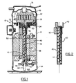
- the crankshaft is described with reference to its use in a scroll-type compressor 10 such as shown in Fig. 1.
- the scroll compressor 10 generally has a fixed scroll 22 mounted in a housing 12, and an orbiting scroll 26 which is fixed against rotation, but which is permitted to revolve in an orbiting motion about the axis of the fixed scroll 22.
- the housing 12 is closed at its upper end with an upper cap 16 and at its lower end with a lower cap 14.
- a pressure dome 18 holds gas that is compressed in the compressor and conducts it to a high pressure outlet 20 after exiting from the center of the fixed scroll which is rigidly mounted within the housing 12.
- a male stub 30 depends from the orbiting scroll 26 at the center or axis thereof to be engaged by a portion of a drive shaft or crankshaft 40 to be hereinafter described in detail.
- the orbiting scroll 26 is fixed against rotation by means of an anti-rotation device, such as an Oldham's ring 32 which prevents rotation of the orbiting scroll 26, but permits the orbiting scroll 26 to revolve without rotation around the center or axis of the fixed scroll 22.
- An electric motor drive for the compressor is carried within the compressor housing 12 and includes a stator armature 36 having a cylindrical passage formed therethrough to receive a rotor assembly 38 rotatably journaled within the compressor housing 12.
- the rotor 38 is positioned within the generally cylindrical passage formed in the stator 36 resulting in a small annular gap therebetween.
- Relative motion between the fixed scroll 22 and the orbiting scroll 26 is provided through a drive shaft 40 which has the electrical rotor 38 press fit thereonto.
- the drive shaft 40 has a generally cylindrically shaped upperbearing cap 42 formed on an upper end of the drive shaft 40 and adapted to receive the stem portion 30 of the orbiting scroll 26. In this manner rotational motion of the rotor 38 within the stator 36 will effect an orbiting motion of the orbiting scroll 26 relative to the fixed scroll 22.
- the bearing cap 42 is journaled within an upper-bearing 34.
- a counterweight 50 is positioned on the drive shaft 40 immediately adjacent the bearing cap 42.
- the counterweight 50 is arcuate in form, in the shape of a segment of a cylinder subtending an arc of approximately 160°, and disposed to the side opposite the radial position of the offset of the orbiting scroll 26.
- the counterweight 50 may be formed as an integral part of the drive shaft 40 or as a separate piece which is secured thereto.
- the counterweight 50 lies at or within the radius of the cylindrical passage in the stator 36 to permit the crank and rotor assembly to be installed from below after the stator 36 has been affixed into the housing 12.
- the drive shaft 40 is formed of a two-piece construction with the bearing cap 42 being preferably formed as a single or separate metal forging, casting or powdered metal piece.
- the shaft portion or rotor stub 41 is preferably formed as a steel tube which is either press fitted, friction or laser welded to the bearing cap 42.
- the main bearing portion, the bearing cap 42 can be fabricated from preferably a near net shape powdered metal process which will greatly reduce the machining time normally associated with constructing this portion of the drive shaft.
- the rotor stub portion of the drive shaft, tube 41, made from a steel tube will require no machining and can be readily attached to the main bearing portion 42 by the above processes. In this manner, the two-piece formation of the drive shaft eliminates time consuming and expensive machining processes heretofore required.
- the lower end of the drive shaft 40 is supported in a lower bearing 58 which journals the lower end of the drive shaft in a position in fluid communication with an oil sump or reservoir 64 which provides a source of lubricating oil for the various bearing surfaces.
- An oil pick-up tube 62 extends from an opening in the lower end of the drive shaft 40 and is immersed in the sump 64.
- An oil distribution bore 66 extends from a chamber 67 formed in the lower end of the drive shaft, and into which the oil pick-up tube 62 is secured, over the length of the drive shaft and into an oil receiving chamber formed in the bearing cap 42.
- the oil distribution bore 66 slants at an angle to the axis of rotation so as to be situated on the side opposite to the position of the conterweight 50.
- a number of oil distribution channels and ports connect with the oil distribution bore 66 to provide lubricant to the upper and lower bearings, as well as any other lube location where lubrication may be required, through centrifugal action upon rotation of the rotor and shaft. Because the rotor stub portion 41 of the drive shaft 40 is formed from a steel tube, a plastic extrusion or molded piece 65 may be utilized to form the oil pick-up tube 62 and oil distribution channels and ports in order to define the desired oil passageways. This process eliminates the need to bore and drill the drive shaft as previously necessary.
Landscapes
- Engineering & Computer Science (AREA)
- Mechanical Engineering (AREA)
- General Engineering & Computer Science (AREA)
- Rotary Pumps (AREA)
- Applications Or Details Of Rotary Compressors (AREA)
- Shafts, Cranks, Connecting Bars, And Related Bearings (AREA)
Applications Claiming Priority (2)
| Application Number | Priority Date | Filing Date | Title |
|---|---|---|---|
| US444944 | 1982-11-29 | ||
| US07/444,944 US5026262A (en) | 1989-11-28 | 1989-11-28 | Multipiece eccentric shaft |
Publications (2)
| Publication Number | Publication Date |
|---|---|
| EP0430854A1 EP0430854A1 (en) | 1991-06-05 |
| EP0430854B1 true EP0430854B1 (en) | 1993-06-23 |
Family
ID=23767007
Family Applications (1)
| Application Number | Title | Priority Date | Filing Date |
|---|---|---|---|
| EP90630199A Expired - Lifetime EP0430854B1 (en) | 1989-11-28 | 1990-11-22 | Multipiece eccentric shaft |
Country Status (7)
| Country | Link |
|---|---|
| US (2) | US5026262A (da) |
| EP (1) | EP0430854B1 (da) |
| JP (1) | JPH03172606A (da) |
| KR (2) | KR910010073A (da) |
| AR (1) | AR245288A1 (da) |
| BR (1) | BR9005923A (da) |
| DK (1) | DK0430854T3 (da) |
Cited By (1)
| Publication number | Priority date | Publication date | Assignee | Title |
|---|---|---|---|---|
| DE102018204691A1 (de) | 2018-03-27 | 2019-10-02 | Volkswagen Aktiengesellschaft | Fluidverteiler zur Fluidkühlung einer Hohlwelle |
Families Citing this family (30)
| Publication number | Priority date | Publication date | Assignee | Title |
|---|---|---|---|---|
| US5366359A (en) * | 1993-08-20 | 1994-11-22 | General Motors Corporation | Scroll compressor orbital scroll drive and anti-rotation assembly |
| US5667371A (en) * | 1996-04-08 | 1997-09-16 | Copeland Corporation | Scroll machine with muffler assembly |
| US5921761A (en) * | 1997-04-17 | 1999-07-13 | Copeland Corporation | Scroll machine with discharge duct |
| US6926632B2 (en) * | 1998-09-14 | 2005-08-09 | Albert W. Brown | Dual drive continuously variable transmission |
| US6193484B1 (en) * | 1998-10-21 | 2001-02-27 | Scroll Technologies | Force-fit scroll compressor assembly |
| EP1194692B1 (en) * | 1999-06-14 | 2004-03-03 | Matsushita Refrigeration Company | Hermetic motor-driven compressor |
| US6289776B1 (en) * | 1999-07-02 | 2001-09-18 | Copeland Corporation | Method and apparatus for machining bearing housing |
| US6220839B1 (en) | 1999-07-07 | 2001-04-24 | Copeland Corporation | Scroll compressor discharge muffler |
| US6328545B1 (en) * | 2000-06-01 | 2001-12-11 | Westinghouse Air Brake Technologies Corporation | Oiless rotary scroll air compressor crankshaft assembly |
| AT5144U1 (de) * | 2001-03-07 | 2002-03-25 | Steyr Powertrain Ag & Co Kg | Welle mit mittels schweissung mit ihr verbundenem teil |
| DE10120399A1 (de) * | 2001-04-25 | 2002-10-31 | Daimler Chrysler Ag | Drehstabfeder |
| KR100428551B1 (ko) * | 2001-12-04 | 2004-04-28 | 삼성광주전자 주식회사 | 밀폐형 왕복식 압축기의 크랭크 샤프트 제조방법 |
| US20060153705A1 (en) * | 2004-11-10 | 2006-07-13 | Horton W T | Drive shaft for compressor |
| US7540815B2 (en) * | 2005-01-11 | 2009-06-02 | Brown Albert W | In-series two chain continuously variable transmission |
| US20060154761A1 (en) * | 2005-01-11 | 2006-07-13 | Brown Albert W | Single chain continuously variable transmission |
| US20060159579A1 (en) * | 2005-01-20 | 2006-07-20 | Skinner Robin G | Motor-compressor unit mounting arrangement for compressors |
| US8147229B2 (en) | 2005-01-20 | 2012-04-03 | Tecumseh Products Company | Motor-compressor unit mounting arrangement for compressors |
| US20070231170A1 (en) * | 2006-03-28 | 2007-10-04 | Xiaogen Su | Drive shaft for a compressor |
| US7967581B2 (en) * | 2008-01-17 | 2011-06-28 | Bitzer Kuhlmaschinenbau Gmbh | Shaft mounted counterweight, method and scroll compressor incorporating same |
| KR100927437B1 (ko) * | 2008-02-29 | 2009-11-19 | 학교법인 두원학원 | 인버터형 스크롤 압축기 |
| KR100964495B1 (ko) * | 2008-02-29 | 2010-06-21 | 학교법인 두원학원 | 오일분리형 구동축을 가지는 스크롤 압축기 |
| JP5143041B2 (ja) * | 2008-04-14 | 2013-02-13 | 株式会社日本自動車部品総合研究所 | 圧縮機 |
| JP4696153B2 (ja) * | 2008-12-15 | 2011-06-08 | 日立アプライアンス株式会社 | 回転型圧縮機 |
| CN102601581A (zh) * | 2012-01-21 | 2012-07-25 | 陈相贤 | 农用耕整地机械的变速箱及其制作方法 |
| US10233927B2 (en) * | 2012-03-23 | 2019-03-19 | Bitzer Kuehlmaschinenbau Gmbh | Scroll compressor counterweight with axially distributed mass |
| CN105127692A (zh) * | 2015-10-08 | 2015-12-09 | 罗光政 | 一种带内防滑齿勾的半闭口u形金属槽的生产方法 |
| US10753359B2 (en) | 2017-07-31 | 2020-08-25 | Trane International Inc. | Scroll compressor shaft |
| CN109458333A (zh) * | 2017-09-06 | 2019-03-12 | 上海海立电器有限公司 | 压缩机及其制造方法 |
| USD861050S1 (en) * | 2017-10-25 | 2019-09-24 | Jung-ping Li | Eccentric shaft for a grinding machine |
| KR102359425B1 (ko) | 2021-11-09 | 2022-02-08 | 정성래 | 편심샤프트 고정장치 |
Family Cites Families (14)
| Publication number | Priority date | Publication date | Assignee | Title |
|---|---|---|---|---|
| JPS5572685A (en) * | 1978-11-29 | 1980-05-31 | Hitachi Ltd | Scroll type fluid machine |
| DE3049117A1 (de) * | 1980-12-24 | 1982-07-01 | Schweizerische Aluminium AG, 3965 Chippis | Antriebswelle, insbesondere fuer fahrzeuge |
| JPS57181984A (en) * | 1981-04-30 | 1982-11-09 | Hitachi Ltd | Rotary shaft of rotary compressor |
| US4488855A (en) * | 1982-12-27 | 1984-12-18 | The Trane Company | Main bearing lubrication system for scroll machine |
| JPS59133984A (ja) * | 1983-01-18 | 1984-08-01 | Toshiba Corp | 圧縮機等の回転軸製造方法 |
| JPS58174176A (ja) * | 1983-03-09 | 1983-10-13 | Hitachi Ltd | 密閉形圧縮機 |
| JPS58174180A (ja) * | 1983-03-16 | 1983-10-13 | Hitachi Ltd | 密閉形圧縮機 |
| JPS60119389A (ja) * | 1983-11-30 | 1985-06-26 | Toshiba Corp | 密閉形圧縮機 |
| JPS60206989A (ja) * | 1984-03-30 | 1985-10-18 | Mitsubishi Electric Corp | スクロ−ル形流体機械 |
| US4704918A (en) * | 1985-02-19 | 1987-11-10 | Kamatics Corporation | Composite material force or motion transmitting member |
| JPH0735790B2 (ja) * | 1986-06-23 | 1995-04-19 | 株式会社日立製作所 | スクロ−ル圧縮機 |
| JPS6380090A (ja) * | 1986-09-24 | 1988-04-11 | Toshiba Corp | ロ−タリコンプレツサの回転軸 |
| JPS63192983A (ja) * | 1987-02-04 | 1988-08-10 | Mitsubishi Electric Corp | スクロ−ル圧縮機 |
| MX172715B (es) * | 1987-11-05 | 1994-01-10 | Emitec Emissionstechnologie | Cigueñales y procedimiento para su fabricacion |
-
1989
- 1989-11-28 US US07/444,944 patent/US5026262A/en not_active Expired - Fee Related
-
1990
- 1990-11-22 BR BR909005923A patent/BR9005923A/pt not_active IP Right Cessation
- 1990-11-22 EP EP90630199A patent/EP0430854B1/en not_active Expired - Lifetime
- 1990-11-22 DK DK90630199.9T patent/DK0430854T3/da active
- 1990-11-26 AR AR90318462A patent/AR245288A1/es active
- 1990-11-27 KR KR1019900019270A patent/KR910010073A/ko not_active Ceased
- 1990-11-28 JP JP2328761A patent/JPH03172606A/ja active Pending
-
1991
- 1991-06-10 US US07/713,194 patent/US5247736A/en not_active Expired - Fee Related
-
1992
- 1992-06-09 KR KR1019920009927A patent/KR930000849A/ko not_active Ceased
Cited By (1)
| Publication number | Priority date | Publication date | Assignee | Title |
|---|---|---|---|---|
| DE102018204691A1 (de) | 2018-03-27 | 2019-10-02 | Volkswagen Aktiengesellschaft | Fluidverteiler zur Fluidkühlung einer Hohlwelle |
Also Published As
| Publication number | Publication date |
|---|---|
| US5026262A (en) | 1991-06-25 |
| BR9005923A (pt) | 1991-09-24 |
| AR245288A1 (es) | 1993-12-30 |
| US5247736A (en) | 1993-09-28 |
| DK0430854T3 (da) | 1993-11-01 |
| EP0430854A1 (en) | 1991-06-05 |
| JPH03172606A (ja) | 1991-07-26 |
| KR930000849A (ko) | 1993-01-15 |
| KR910010073A (ko) | 1991-06-28 |
Similar Documents
| Publication | Publication Date | Title |
|---|---|---|
| EP0430854B1 (en) | Multipiece eccentric shaft | |
| JP2712914B2 (ja) | スクロール圧縮機 | |
| US5320506A (en) | Oldham coupling for scroll compressor | |
| AU608661B2 (en) | Scroll compressor | |
| US4340339A (en) | Scroll type compressor with oil passageways through the housing | |
| EP0052234B1 (en) | Scroll type fluid displacement apparatus with oil separating mechanism | |
| EP0122469B1 (en) | Lubricating mechanism for scroll-type fluid displacement apparatus | |
| EP1674846A1 (en) | Scroll machine having counterweights with changeable cavity | |
| JPH0735794B2 (ja) | 駆動軸の製造方法 | |
| JPS63109291A (ja) | スクロ−ル圧縮機 | |
| AU644565B2 (en) | Scroll compressor including drive pin and roller assembly having sliding wedge member | |
| US6179591B1 (en) | Conical hub bearing for scroll machine | |
| EP0432084B1 (en) | Scroll compressor with unitary crankshaft, upper bearing and counterweight | |
| PH26403A (en) | Motor compressor bearing assembly | |
| EP0039622A1 (en) | Improvements in or relating to fluid displacement apparatus | |
| JPH10220369A (ja) | スクロール圧縮機 | |
| JP2734408B2 (ja) | スクロール圧縮機 | |
| CN120693446A (zh) | 驱动轴组件和包括驱动轴组件的压缩机 | |
| JP2930046B2 (ja) | スクロール圧縮機 | |
| AU649154B2 (en) | Fluid pump and rotary machine having said fluid pump | |
| JPH0637875B2 (ja) | スクロ−ル圧縮機 | |
| JP4281128B2 (ja) | スクロール形流体機械 | |
| EP0452896B1 (en) | Lubrication for scroll compressor | |
| MXPA00010452A (es) | Maquina de espiral | |
| JPH0458085A (ja) | 流体圧縮機 |
Legal Events
| Date | Code | Title | Description |
|---|---|---|---|
| PUAI | Public reference made under article 153(3) epc to a published international application that has entered the european phase |
Free format text: ORIGINAL CODE: 0009012 |
|
| AK | Designated contracting states |
Kind code of ref document: A1 Designated state(s): BE DK FR GB |
|
| 17P | Request for examination filed |
Effective date: 19911018 |
|
| 17Q | First examination report despatched |
Effective date: 19920925 |
|
| GRAA | (expected) grant |
Free format text: ORIGINAL CODE: 0009210 |
|
| AK | Designated contracting states |
Kind code of ref document: B1 Designated state(s): BE DK FR GB |
|
| ET | Fr: translation filed | ||
| REG | Reference to a national code |
Ref country code: DK Ref legal event code: T3 |
|
| PLBE | No opposition filed within time limit |
Free format text: ORIGINAL CODE: 0009261 |
|
| STAA | Information on the status of an ep patent application or granted ep patent |
Free format text: STATUS: NO OPPOSITION FILED WITHIN TIME LIMIT |
|
| 26N | No opposition filed | ||
| PG25 | Lapsed in a contracting state [announced via postgrant information from national office to epo] |
Ref country code: GB Effective date: 19941122 |
|
| GBPC | Gb: european patent ceased through non-payment of renewal fee |
Effective date: 19941122 |
|
| PGFP | Annual fee paid to national office [announced via postgrant information from national office to epo] |
Ref country code: FR Payment date: 19951009 Year of fee payment: 6 |
|
| PGFP | Annual fee paid to national office [announced via postgrant information from national office to epo] |
Ref country code: DK Payment date: 19951016 Year of fee payment: 6 Ref country code: BE Payment date: 19951016 Year of fee payment: 6 |
|
| PG25 | Lapsed in a contracting state [announced via postgrant information from national office to epo] |
Ref country code: DK Effective date: 19961122 |
|
| REG | Reference to a national code |
Ref country code: DK Ref legal event code: EBP |
|
| PG25 | Lapsed in a contracting state [announced via postgrant information from national office to epo] |
Ref country code: BE Effective date: 19961130 |
|
| BERE | Be: lapsed |
Owner name: CARRIER CORP. Effective date: 19961130 |
|
| PG25 | Lapsed in a contracting state [announced via postgrant information from national office to epo] |
Ref country code: FR Effective date: 19970731 |
|
| REG | Reference to a national code |
Ref country code: FR Ref legal event code: ST |