EP0430857A2 - Methode zum Verlängern der Haltbarkeitsdauer von Kesselröhren - Google Patents
Methode zum Verlängern der Haltbarkeitsdauer von Kesselröhren Download PDFInfo
- Publication number
- EP0430857A2 EP0430857A2 EP90630207A EP90630207A EP0430857A2 EP 0430857 A2 EP0430857 A2 EP 0430857A2 EP 90630207 A EP90630207 A EP 90630207A EP 90630207 A EP90630207 A EP 90630207A EP 0430857 A2 EP0430857 A2 EP 0430857A2
- Authority
- EP
- European Patent Office
- Prior art keywords
- tube
- tubes
- temperature
- boiler
- step comprises
- Prior art date
- Legal status (The legal status is an assumption and is not a legal conclusion. Google has not performed a legal analysis and makes no representation as to the accuracy of the status listed.)
- Granted
Links
Images


Classifications
-
- F—MECHANICAL ENGINEERING; LIGHTING; HEATING; WEAPONS; BLASTING
- F22—STEAM GENERATION
- F22B—METHODS OF STEAM GENERATION; STEAM BOILERS
- F22B35/00—Control systems for steam boilers
- F22B35/18—Applications of computers to steam-boiler control
-
- Y—GENERAL TAGGING OF NEW TECHNOLOGICAL DEVELOPMENTS; GENERAL TAGGING OF CROSS-SECTIONAL TECHNOLOGIES SPANNING OVER SEVERAL SECTIONS OF THE IPC; TECHNICAL SUBJECTS COVERED BY FORMER USPC CROSS-REFERENCE ART COLLECTIONS [XRACs] AND DIGESTS
- Y10—TECHNICAL SUBJECTS COVERED BY FORMER USPC
- Y10S—TECHNICAL SUBJECTS COVERED BY FORMER USPC CROSS-REFERENCE ART COLLECTIONS [XRACs] AND DIGESTS
- Y10S122/00—Liquid heaters and vaporizers
- Y10S122/13—Tubes - composition and protection
Definitions
- tube outlet steam temperatures and tube metal temperatures are not uniform throughout the tube circuits. While the bulk steam temperature at the tube circuit outlet header may typically be 1005°F, the local steam temperatures in some of the tubes can be as much as 150°F higher or lower than the bulk temperature. These temperature variations typically occur both across the tube circuit from left to right and through each tube assembly in the direction of the gas flow. The cause of these variations is typically a combination of nonuniform gas velocity and temperature distributions, steam flow imbalance, and intrinsic characteristics of convection pass heat transfer surface arrangements. In general, boiler manufacturers attempt to account for these temperature variations by specifying tube and header materials and thicknesses based upon worst case design conditions.
- boilers with a tangential firing pattern are usually hotter on one side of the superheater and reheater sections.
- Front and rear wall fired boilers typically have hot spots at the quarter points on the header.
- These temperatures are the result of gas side and steam side flow imbalances occurring across the unit that are partially addressed in the original design calculations.
- the reality of the large temperature differences is that tube materials and header geometry have generally not been adequately designed to withstand these differences.
- material changes are made in a circuit from the inlet to the outlet, but the same materials are used across the unit.
- Each assembly across a unit is identical even though temperature differences can vary by as much as 150°F. This temperature difference is almost as large as the temperature difference from the inlet to the outlet in a particular tube assembly.
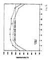
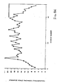
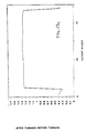
- Figure 1 shows a typical profile of the steam temperature at the tube outlet legs of a superheater situated in a fossil fueled boiler. These temperatures were obtained from thermocouples welded to the outside of tubes just upstream of the outlet header. Since there is negligible heat flux in this region, this measured temperature is indicative of both metal temperature and steam temperature at the tube outlet. Note that in the center of the superheater, steam temperatures are substantially higher than the design bulk steam temperature of 1005°F, while at either side of the superheater, the steam temperature is substantially below this value.
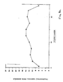
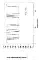
- Figure 2b expands the upper portion of the curve of Figure 2a. It can be seen that if the temperature of this tube could be lowered at the 200,000 hour point, then its remaining life could be significantly extended. For instance, by lowering the temperature 30°F, the remaining life would be extended from 25,000 to 75,000 hours.
- Each tube will have its own unique life gain depending on when and how much its temperature is reduced, how fast creep damage is accumulating, how much original life remains, and the wall thinning rate due to fireside erosion.
- a method of increasing the reliability and remaining useful life of a boiler tube system whereby the current condition of the tubes is evaluated; the temperature of the tubes during operation of the boiler is obtained and a tube-to-tube outlet temperature profile is developed therefrom; the steam flow redistribution which would be required in the tubes in order to alter the temperature distribution across the tubes is determined; and the tubes are modified in order to achieve the required flow redistribution.
- the condition of the tubes is ascertained by performing a non-destructive evaluation, such as ultrasonic examination, and calculating the remaining useful life of the tubes. Stress and creep conditions are determined for each tube and a failure point is predicted. Using a model of the system, its characteristics are manipulated to predict a profile which will extend the useful life and reliability of the system. Then the physical system is modified by installing steam flow controllers to redistribute the steam flow and achieve extended life and reliability from the system.
- Figure 1 is a graph illustrating the steam temperature profile across superheater outlet legs.
- Figures 2a and 2b are graphs illustrating creep damage accumulation versus remaining life of typical superheater tubes.
- Figure 3 is a flow chart illustrating the steps of the method of the present invention.
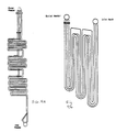
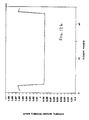
- Figures 4a and 4b are schematic elevational views of sections of superheater and reheater tubing.
- Figure 6 is a plan diagram of a steam flow controller.
- Figure 7a is a schematic elevational view of sections of superheater tubing.
- Figure 7b is a cross sectional view of the tubes of Figure 7a showing the locations where non-destructive testing is performed according to the present invention.
- Figures 8a through 8d are graphs illustrating oxide scale measurements on superheater tubing in accordance with the present invention.
- Figure 9 is a graph illustrating outlet temperature measurements on superheater tubing in accordance with the present invention.
- Figure 10 is a cross-sectional diagram of the outlet of a superheater showing placement of steam flow controllers in accordance with the present invention.
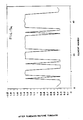
- Figure 11 is a schematic elevational view of sections of superheater tubing showing tubes to be replaced in accordance with the present invention.
- Figures 12a through 12d are graphs illustrating tube steam temperature ratios before and after modification in accordance with the present invention.
- Figure 3 is a flow chart illustrating the basic procedure for extending the useful life of boiler tubes according to the present invention. It is to be understood that the method of the present invention applies to all types of boiler tubes. Further, the order of the steps is not meant to be limiting, but merely explanatory. The order in which the steps may be performed can change from case to case.
- step 100 the current condition of the superheater is ascertained by examination of the superheater tubes. This entails measuring the wall thickness and steamside oxide scale buildup at numerous points in the system.
- step 104 a cost/benefit analysis is made to determine whether the expenditure required to extend tube life is economically justified.
- step 106 field testing of the tubes occurs. This includes collecting inlet and outlet tube leg temperature, bulk steam flowrate and pressure. A temperature profile is then developed. Further, background data is compiled. This includes collecting operating data for the boiler, including number of operating hours, bulk steam outlet temperature and pressure, and steam flowrate at different loads, and design information for the superheater, including tube dimensions (lengths, outside diameter, and wall thickness), tube material, and tube assembly configurations. The operating data is routinely available in plant logs as part of the operating history of the boiler.
- step 108 the tube system is mathematically modeled in order to determine optimum pressure and temperature conditions which would extend the life of the tube system.
- step 110 the tubes are modified to obtain the desired life-extending performance specification.
- NDE non-destructive examination
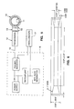
- a hand-held contact ultrasonic shear wave transducer 12 such as model V222-BA hand-held shear wave transducer produced by Panametrics of Waltham, Massachusetts, with a replaceable, variable length or fixed length delay line 13, is positioned on the clean, outer surface of a tube 10 with a high viscosity shear wave couplant 14 positioned between the transducer 12 and the delay line 13 and between the delay line 13 and the steel tube 10.
- the delay line 13 utilizes a delay medium such as quartz or Plexiglas and improves the signal-to-noise ratio for certain combinations of tube and oxide thicknesses.
- a different length line may be used for different combinations of tube and oxide thicknesses.
- Transducer 12 is electrically connected via a coaxial cable 15 to a high-frequency pulse/receiver 16.
- Receiver 16 is connected to a delayed time pulse overlap oscilloscope 17 having a delayed time base and pulse overlap feature for conveniently and accurately measuring the differential time of flight.
- the transducer 12 is a high-frequency shear wave transducer.
- the transducer operates at 20 MHz and has a circular active element with a diameter of 0.25 inches.
- Transducer 12 is positioned so that the ultrasonic shear wave beam is directed normal to the inside surface of the tube.
- An ultrasonic signal is then generated and received by the high frequency pulse/receiver 16.
- the signal is displayed on the oscilloscope 17.
- the time of flight technique does not produce an absolute or exact scale thickness.
- the time of flight data is related to actual scale thickness measurement established by physical techniques such as metallurgical examination. Ultrasonic and metallurgical results are related by the following equation:
- An actual scale thickness standard is predetermined by subjecting a plurality of samples of the boiler tubes which include varying thickness of scale to ultrasonic pulses to determine the time of flight within the scale. Thereafter, the scale on the samples is physically measured and a formula or conversion curve relating scale thickness to the time of flight of the pulses in the scale is established. This predetermined standard, i.e., curve or formula, is used in further testing thereby obviating the need for further destructive tests.
- an average stress value SA is derived in a series of calculations based on the measured internal scale thickness TK, the maximum wall thickness W1, the minimum wall thickness W2, the steam pressure PR, and the specified outside diameter of the tube OD, as follows:
- a projected creep condition is then derived for incremental time periods based on hoop stress and the Larson-Miller parameter, assuming linear oxide growth and linear wall thinning rates.
- the creep condition is quantified by the average stress SA and the LMP.
- the scale thickness at failure TF is calculated from equation (5) rearranged as:
- thermodynamic profile of the tubes is developed for various load conditions.
- the inlet and outlet temperatures may be measured utilizing existing thermocouples and by placing additional thermocouples, as needed, at the same location on several elements of the tubing and plotting the readings. It is economically impractical to put thermocouples on each tube, so a pattern is established to obtain representative temperature data by instrumenting typically 5% to 20% of the tubes. This pattern is dictated by the degree of nonuniformity exhibited by the oxide scale thickness profiles. Most of the thermocouples are installed on tube outlet legs, with less than a dozen installed on inlet legs. Pressure and flow rates at both the inlet and outlet are also obtained. The resultant temperature profiles will indicate the tubes carrying the hottest steam in the section. One example is illustrated in Figure 1, where it can be seen that the temperature is cooler at the outside tubes, increasing almost 150° at the middle tubes.
- the arrangement of the tube sections is mathematically modeled.
- the inlet and outlet conditions of each tube are measured or estimated.
- the tube circuit geometry is modeled based on the design drawings.
- the heat flux for each tube circuit is calculated based on an estimate of the enthalpy increase through the circuit and the surface area of the tubing.
- Steam thermodynamic and fluid transport properties may be determined by readily available means given the basic operating parameters, such as temperature and pressure.
- Basic engineering equations are used to determine the estimated pressure, the steam temperature, and the steam to scale interface temperature.
- the estimated pressure is a function of the length of the tube segment and the internal diameter of the tube segment.
- temperatures at the tube midwall and the metal to scale interface are calculated at each tube material change location, based on the temperature of the steam to scale interface temperature and the following equation:
- the invention described here has the additional flexibility to accommodate changes in boiler operation.
- the life expended for each tube in the system up to the point in time when redesign occurs depends upon past boiler fireside conditions.
- the redesign incorporating steam flow redistribution permits these fireside conditions to be changed for future boiler operation.
- Any changes in fireside conditions for future operation are quantified with the tube outlet leg thermocouple data that are collected in the field testing of the tubes, as described in step 106 of Figure 3.
- the remaining useful life of each tube is thus a function of the tube life already expended under past fireside conditions and the future tube life consumption rate under future fireside conditions.
- the change in hoop stress is calculated as a function of constant internal pressure and diminishing tube wall thickness.
- the change in metal temperature with respect to time is calculated from heat flow equation (8), which takes into account the increasing steamside scale thickness in the presence of a constant heat flux through the tube wall and across the internal scale.
- the initial tube metal temperature is set equal to the steam to scale interface temperature calculated above. Then, the values for time, metal temperature, scale temperature, stress, and scale thickness are increased using the heat transfer equation (8) and the scale thickness kinetic equation (9).
- Creep damage of each time increment is expressed by the following equation: where DR is the creep damage ratio, TI is the time increment in hours, and FH is the hours projected to failure at the given stress and temperature.
- the overall creep damage is accumulated as the sum of the damage ratios of the individual time increments. Creep rupture is predicted when the damage ratio equals one.
- Minimum and mean creep rupture material properties are based on data published in the ASTM Creep Rupture Data Series. An acceptable failure probability must be selected. A normal distribution about the mean in the ASTM failure curves is assumed, and the minimum failure line corresponds to a 5 percent probability of failure.
- That input consists of a set of desired temperature changes, whereby the tube outlet leg temperature for the hot tubes are reduced and those for the cold tubes are increased.
- a one-time input is the complete matrix of tube dimensions, including all lengths, outer diameters, and wall thicknesses.
- An iterative input is the desired change in tube outlet steam temperature as specified in the previous step.
- the model redistributes the tube-to-tube steam flow, while maintaining total steam flow constant, in order to achieve the desired changes in each tube outlet temperature.
- the model solves the conservation of mass, momentum, and energy equations for steam flow in all tubes simultaneously, yielding the following equation: where the subscripts are defined as:
- SFC's steam flow controllers
- SFC's steam flow controllers
- Another critical parameter output of the model is the magnitude of the slight increase in pressure drop across the superheater due to the presence of the SFC's.
- FIG. 6 illustrates a typical SFC design.
- the SFC is made as long as practical (e.g., approximately one foot so that the diameter restriction can be minimized).
- a three-to-one taper is used at the entrance and exit to comply with ASME codes and to minimize flow separation and the formation of eddies, as well as eliminate any propensity for plugging.
- This SFC design is essentially a tube dutchman that is installed with two circumferential welds in the place of a removed tube section.
- This design does not have the drawbacks of a sharp edged orifice design, such as steam erosion of the orifice inner diameter with subsequent change in flow characteristics, a tendency to cause buildup of deposits upstream and downstream of the orifice, and possibly pluggage.
- Some tubes may have virtually no remaining useful life and thus must be replaced. This may occur due to wall thinning or high temperatures.
- Table 1 shows the original design specifications for each section, including outside tube diameter OD, specified minimum wall thickness SW, and tube material MA.
- a total of 130 NDE measurements are taken on the superheater 200. Of these, 120 are recorded on the outlet header tube legs at area 202. Tubes 211 and 214 are examined on every element and tubes 212 and 213 are examined on every fifth element, as illustrated in Figure 7b. Ten measurements are taken in the furnace section at area 204 across selected elements of tube 4. The results are compiled in table 2.
- the current remaining life in area 204 is shown to range from 15,000 hours to 66,000 hours.
- the current remaining life for all tubing in area 202 exceeds 85,000 hours.
- Figures 8a through 8d shown the measured oxide scale thickness for rows 211 through 214 in area 202. These figures also show the temperature profile, since thicker oxide scale correlates to higher effective tube metal temperatures. In that regard, it is seen that there is a temperature variation across the rows, with row 214 having the hottest tubes.
- SFC's are installed at the inlet header of the superheater 200 according to the pattern illustrated in Figure 10.
- a single size of SFC is chosen.
- Each SFC has a 2-inch outside diameter, a 0.639-inch thick wall, and is 16 inches long.
- the material is ASME SA-213-T11.
- the SFC's are installed in the tubing at the stub weld near the inlet header.
- a minimum 3: 1 taper of the inside diameter should be utilized.
Landscapes
- Engineering & Computer Science (AREA)
- General Engineering & Computer Science (AREA)
- Combustion & Propulsion (AREA)
- Physics & Mathematics (AREA)
- Thermal Sciences (AREA)
- Mechanical Engineering (AREA)
- Chemical & Material Sciences (AREA)
- Testing Resistance To Weather, Investigating Materials By Mechanical Methods (AREA)
- Paper (AREA)
- Control Of Steam Boilers And Waste-Gas Boilers (AREA)
- Fluidized-Bed Combustion And Resonant Combustion (AREA)
- Production Of Liquid Hydrocarbon Mixture For Refining Petroleum (AREA)
- Control Of Combustion (AREA)
- Monitoring And Testing Of Nuclear Reactors (AREA)
- Testing Of Devices, Machine Parts, Or Other Structures Thereof (AREA)
Applications Claiming Priority (2)
| Application Number | Priority Date | Filing Date | Title |
|---|---|---|---|
| US07/444,043 US5050108A (en) | 1989-11-30 | 1989-11-30 | Method for extending the useful life of boiler tubes |
| US444043 | 1989-11-30 |
Publications (3)
| Publication Number | Publication Date |
|---|---|
| EP0430857A2 true EP0430857A2 (de) | 1991-06-05 |
| EP0430857A3 EP0430857A3 (en) | 1992-03-04 |
| EP0430857B1 EP0430857B1 (de) | 1996-07-03 |
Family
ID=23763251
Family Applications (1)
| Application Number | Title | Priority Date | Filing Date |
|---|---|---|---|
| EP90630207A Expired - Lifetime EP0430857B1 (de) | 1989-11-30 | 1990-11-30 | Methode zum Verlängern der Haltbarkeitsdauer von Kesselröhren |
Country Status (6)
| Country | Link |
|---|---|
| US (1) | US5050108A (de) |
| EP (1) | EP0430857B1 (de) |
| AT (1) | ATE140075T1 (de) |
| CA (1) | CA2030414C (de) |
| DE (1) | DE69027653T2 (de) |
| ES (1) | ES2092499T3 (de) |
Families Citing this family (26)
| Publication number | Priority date | Publication date | Assignee | Title |
|---|---|---|---|---|
| US5210704A (en) * | 1990-10-02 | 1993-05-11 | Technology International Incorporated | System for prognosis and diagnostics of failure and wearout monitoring and for prediction of life expectancy of helicopter gearboxes and other rotating equipment |
| US5349481A (en) * | 1993-06-10 | 1994-09-20 | Exabyte Corporation | Apparatus and method for distorted track data recovery by rewinding and re-reading the tape at a slower than nominal speed |
| LTIP1892A (en) * | 1993-06-15 | 1994-12-27 | Combustion Eng | Corrosian analysis system and method |
| EP1010114A1 (de) * | 1996-11-27 | 2000-06-21 | Sundstrand Corporation, Inc. | Methode zur unterhaltung von komponenten die ermüdung unterliegen |
| JP3311316B2 (ja) * | 1999-09-10 | 2002-08-05 | 本田技研工業株式会社 | 熱サイクルを受ける物品の寿命評価方法 |
| US6532421B2 (en) * | 2000-04-07 | 2003-03-11 | Toho Gas Co., Ltd | Method for estimating a life of apparatus under narrow-band random stress variation |
| US7249885B2 (en) * | 2002-10-16 | 2007-07-31 | Clyde Bergemann Gmbh | Heat flux measuring device for pressure pipes, method for producing a measuring device, method for monitoring an operating state of a heat exchanger, heat exchanger and method for measuring a heat flux |
| EP3395508A1 (de) | 2005-06-30 | 2018-10-31 | Intuitive Surgical Operations Inc. | Indikator zur kommunikation des werkzeugstatus in der mehrarmigen robotischen telechirurgie |
| US8273076B2 (en) * | 2005-06-30 | 2012-09-25 | Intuitive Surgical Operations, Inc. | Indicator for tool state and communication in multi-arm robotic telesurgery |
| EP1811282A1 (de) * | 2006-01-20 | 2007-07-25 | ABB Technology AG | Degradationsüberwachung von Kesselrohren |
| US7715991B2 (en) * | 2007-05-17 | 2010-05-11 | General Electric Company | Systems and methods for monitoring energy system components |
| US9939395B2 (en) * | 2007-05-18 | 2018-04-10 | Environmental Energy Services, Inc. | Method for measuring ash/slag deposition in a utility boiler |
| US8381690B2 (en) | 2007-12-17 | 2013-02-26 | International Paper Company | Controlling cooling flow in a sootblower based on lance tube temperature |
| US8423397B2 (en) * | 2008-08-08 | 2013-04-16 | Pinnacleais, Llc | Asset management systems and methods |
| US20100036866A1 (en) * | 2008-08-11 | 2010-02-11 | Pinnacleais, Llc | Piping Circuitization System and Method |
| US9212569B2 (en) * | 2010-10-19 | 2015-12-15 | General Electric Company | Systems, methods, and apparatus for determining online stress and life consumption of a heat recovery steam generator |
| US8874415B2 (en) | 2012-01-04 | 2014-10-28 | General Electric Company | System and method for forming failure estimates for a heat recovery steam generator |
| BR112014031938B1 (pt) | 2012-10-12 | 2021-09-21 | Methanex New Zealand Limited | Método para o monitoramento da temperatura de um tubo de reformador em um reator de reformador, e reator que utiliza o método |
| US9541282B2 (en) * | 2014-03-10 | 2017-01-10 | International Paper Company | Boiler system controlling fuel to a furnace based on temperature of a structure in a superheater section |
| CA2955299C (en) | 2014-07-25 | 2017-12-12 | International Paper Company | System and method for determining a location of fouling on boiler heat transfer surface |
| US9927231B2 (en) * | 2014-07-25 | 2018-03-27 | Integrated Test & Measurement (ITM), LLC | System and methods for detecting, monitoring, and removing deposits on boiler heat exchanger surfaces using vibrational analysis |
| US11215574B2 (en) | 2016-05-09 | 2022-01-04 | Haldor Topsøe A/S | Monitoring of heated tubes |
| JP6721273B2 (ja) * | 2016-10-25 | 2020-07-08 | 一般財団法人電力中央研究所 | ボイラ水冷壁管材の化学洗浄時期の決定方法、決定装置、及び決定プログラム |
| US20210341140A1 (en) | 2020-05-01 | 2021-11-04 | International Paper Company | System and methods for controlling operation of a recovery boiler to reduce fouling |
| TWI783803B (zh) * | 2021-12-01 | 2022-11-11 | 台灣電力股份有限公司 | 蒸汽壓力量測方法 |
| JP7815038B2 (ja) * | 2022-06-06 | 2026-02-17 | 東芝エネルギーシステムズ株式会社 | 許容応力算出装置、許容応力算出方法、および、許容応力算出プログラム |
Family Cites Families (11)
| Publication number | Priority date | Publication date | Assignee | Title |
|---|---|---|---|---|
| US3250259A (en) * | 1959-08-19 | 1966-05-10 | Sulzer Ag | Method and apparatus for controlling rate of temperature changes of heat generators during startup and shutdown |
| US4231419A (en) * | 1978-07-21 | 1980-11-04 | Kraftwerk Union Aktiengesellschaft | Manipulator for inspection and possible repair of the tubes of heat exchangers, especially of steam generators for nuclear reactors |
| JPS59176501A (ja) * | 1983-03-28 | 1984-10-05 | 株式会社日立製作所 | ボイラチユ−ブ |
| JPS60226603A (ja) * | 1984-04-24 | 1985-11-11 | バブコツク日立株式会社 | ボイラ熱応力予測装置 |
| US4628870A (en) * | 1984-07-31 | 1986-12-16 | Westinghouse Electric Corp. | Model steam generator having means to facilitate inspection of sample tubes |
| US4713870A (en) * | 1985-03-26 | 1987-12-22 | Raychem Corporation | Pipe repair sleeve apparatus and method of repairing a damaged pipe |
| US4685334A (en) * | 1986-01-27 | 1987-08-11 | The Babcock & Wilcox Company | Method for ultrasonic detection of hydrogen damage in boiler tubes |
| US4669310A (en) * | 1986-03-26 | 1987-06-02 | The Babcock & Wilcox Company | High frequency ultrasonic technique for measuring oxide scale on the inner surface of boiler tubes |
| US4716767A (en) * | 1986-04-07 | 1988-01-05 | Foster Wheeler Energy Corporation | Rupture testing apparatus for boiler tubes |
| US4908775A (en) * | 1987-02-24 | 1990-03-13 | Westinghouse Electric Corp. | Cycle monitoring method and apparatus |
| US4941512A (en) * | 1988-11-14 | 1990-07-17 | Cti Industries, Inc. | Method of repairing heat exchanger tube ends |
-
1989
- 1989-11-30 US US07/444,043 patent/US5050108A/en not_active Expired - Lifetime
-
1990
- 1990-11-21 CA CA002030414A patent/CA2030414C/en not_active Expired - Fee Related
- 1990-11-30 AT AT90630207T patent/ATE140075T1/de active
- 1990-11-30 EP EP90630207A patent/EP0430857B1/de not_active Expired - Lifetime
- 1990-11-30 DE DE69027653T patent/DE69027653T2/de not_active Expired - Fee Related
- 1990-11-30 ES ES90630207T patent/ES2092499T3/es not_active Expired - Lifetime
Also Published As
| Publication number | Publication date |
|---|---|
| US5050108A (en) | 1991-09-17 |
| DE69027653D1 (de) | 1996-08-08 |
| CA2030414A1 (en) | 1991-05-31 |
| DE69027653T2 (de) | 1997-02-20 |
| EP0430857B1 (de) | 1996-07-03 |
| ATE140075T1 (de) | 1996-07-15 |
| EP0430857A3 (en) | 1992-03-04 |
| CA2030414C (en) | 1997-10-28 |
| ES2092499T3 (es) | 1996-12-01 |
Similar Documents
| Publication | Publication Date | Title |
|---|---|---|
| US5050108A (en) | Method for extending the useful life of boiler tubes | |
| CN112284897B (zh) | 核电机组蒸汽发生器传热管微振磨损损伤处理方法 | |
| Vakhguelt et al. | Combination non-destructive test (NDT) method for early damage detection and condition assessment of boiler tubes | |
| KR940007532A (ko) | 세라믹 결정체와 그의 변화를 진단하는 방법 및 장치 | |
| JP2002156325A (ja) | 金属部材の表面き裂深さ解析方法 | |
| JPH09218195A (ja) | ボイラ管寄スタッブ管台の損傷評価方法 | |
| CN113138129B (zh) | 一种基于l-m参数法的电站材料力学性能变化规律获得方法 | |
| Braschel et al. | Thermal stratification in steam generator feedwater lines | |
| CN116127620A (zh) | 一种基于热电势的铸造不锈钢热老化单轴疲劳预测方法 | |
| JPH0875107A (ja) | 高温耐圧部の寿命評価法 | |
| Thoraval | Creep of high temperature steam piping: EDF experience with fossil-fired power plants from 1955 to 1987 | |
| Cohn et al. | Optimization of NDE Reexamination Locations and Intervals for Grade 91 Piping System Girth Welds | |
| Kumar et al. | Life Assessment of Super Heater and Reheater Tubes through Steam Side Oxide Scale Measurements-CPRI Experience | |
| Bakić et al. | Thermal history and stress state of a fresh steam-pipeline influencing its remaining service life | |
| WO2019230608A1 (ja) | クリープ寿命評価方法 | |
| Bisbee et al. | The Role of NDE in Maximizing the Value of High Temperature Tubing | |
| JPS6067838A (ja) | 高温で使用される構造部材の損傷診断方法およびその装置 | |
| Vikash et al. | Remnant Life Assessment of High Temperature Tubes in 250MW Boiler | |
| Lu et al. | On-line stress calculation and life monitoring systems for boiler components | |
| Smith et al. | High-temperature corrosion-fatigue (circumferential) cracking life evaluation procedure for low alloy (Cr-Mo) boiler tube steels | |
| JPH0127377B2 (de) | ||
| JP2003065914A (ja) | オーステナイト鋼伝熱管材の使用温度及びクリープ損傷推定方法 | |
| Jaske et al. | Assessing the Condition and Estimating the Remaining Lives of Pressure Components in a Methanol Plant Reformer: Part 2—Engineering Evaluation | |
| Marzuki et al. | The Study of Difference Piping Wall Thickness Against the Difference Pressure Applied at UTHM Biodiesel Plant Using Simulation Method | |
| Rodgers et al. | Acoustic emission monitoring for inspection of seam-welded hot reheat piping in fossil power plants |
Legal Events
| Date | Code | Title | Description |
|---|---|---|---|
| PUAI | Public reference made under article 153(3) epc to a published international application that has entered the european phase |
Free format text: ORIGINAL CODE: 0009012 |
|
| AK | Designated contracting states |
Kind code of ref document: A2 Designated state(s): AT BE CH DE DK ES FR GB GR IT LI LU NL SE |
|
| PUAL | Search report despatched |
Free format text: ORIGINAL CODE: 0009013 |
|
| AK | Designated contracting states |
Kind code of ref document: A3 Designated state(s): AT BE CH DE DK ES FR GB GR IT LI LU NL SE |
|
| 16A | New documents despatched to applicant after publication of the search report | ||
| 17P | Request for examination filed |
Effective date: 19920901 |
|
| 17Q | First examination report despatched |
Effective date: 19940119 |
|
| GRAH | Despatch of communication of intention to grant a patent |
Free format text: ORIGINAL CODE: EPIDOS IGRA |
|
| GRAH | Despatch of communication of intention to grant a patent |
Free format text: ORIGINAL CODE: EPIDOS IGRA |
|
| GRAA | (expected) grant |
Free format text: ORIGINAL CODE: 0009210 |
|
| AK | Designated contracting states |
Kind code of ref document: B1 Designated state(s): AT BE CH DE DK ES FR GB GR IT LI LU NL SE |
|
| PG25 | Lapsed in a contracting state [announced via postgrant information from national office to epo] |
Ref country code: IT Free format text: LAPSE BECAUSE OF FAILURE TO SUBMIT A TRANSLATION OF THE DESCRIPTION OR TO PAY THE FEE WITHIN THE PRE;WARNING: LAPSES OF ITALIAN PATENTS WITH EFFECTIVE DATE BEFORE 2007 MAY HAVE OCCURRED AT ANY TIME BEFORE 2007. THE CORRECT EFFECTIVE DATE MAY BE DIFFERENT FROM THE ONE RECORDED.SCRIBED TIME-LIMIT Effective date: 19960703 Ref country code: NL Free format text: LAPSE BECAUSE OF FAILURE TO SUBMIT A TRANSLATION OF THE DESCRIPTION OR TO PAY THE FEE WITHIN THE PRESCRIBED TIME-LIMIT Effective date: 19960703 Ref country code: GR Free format text: LAPSE BECAUSE OF FAILURE TO SUBMIT A TRANSLATION OF THE DESCRIPTION OR TO PAY THE FEE WITHIN THE PRESCRIBED TIME-LIMIT Effective date: 19960703 Ref country code: FR Free format text: THE PATENT HAS BEEN ANNULLED BY A DECISION OF A NATIONAL AUTHORITY Effective date: 19960703 Ref country code: LI Effective date: 19960703 Ref country code: DK Effective date: 19960703 Ref country code: BE Effective date: 19960703 Ref country code: CH Effective date: 19960703 Ref country code: AT Effective date: 19960703 |
|
| REF | Corresponds to: |
Ref document number: 140075 Country of ref document: AT Date of ref document: 19960715 Kind code of ref document: T |
|
| RAP4 | Party data changed (patent owner data changed or rights of a patent transferred) |
Owner name: APTECH ENGINEERING SERVICES, INC. |
|
| REF | Corresponds to: |
Ref document number: 69027653 Country of ref document: DE Date of ref document: 19960808 |
|
| PG25 | Lapsed in a contracting state [announced via postgrant information from national office to epo] |
Ref country code: SE Effective date: 19961003 |
|
| PG25 | Lapsed in a contracting state [announced via postgrant information from national office to epo] |
Ref country code: LU Free format text: LAPSE BECAUSE OF NON-PAYMENT OF DUE FEES Effective date: 19961130 |
|
| REG | Reference to a national code |
Ref country code: ES Ref legal event code: FG2A Ref document number: 2092499 Country of ref document: ES Kind code of ref document: T3 |
|
| NLV1 | Nl: lapsed or annulled due to failure to fulfill the requirements of art. 29p and 29m of the patents act | ||
| EN | Fr: translation not filed | ||
| REG | Reference to a national code |
Ref country code: CH Ref legal event code: PL |
|
| PLBE | No opposition filed within time limit |
Free format text: ORIGINAL CODE: 0009261 |
|
| STAA | Information on the status of an ep patent application or granted ep patent |
Free format text: STATUS: NO OPPOSITION FILED WITHIN TIME LIMIT |
|
| 26N | No opposition filed | ||
| PGFP | Annual fee paid to national office [announced via postgrant information from national office to epo] |
Ref country code: GB Payment date: 19991208 Year of fee payment: 10 |
|
| PGFP | Annual fee paid to national office [announced via postgrant information from national office to epo] |
Ref country code: DE Payment date: 19991210 Year of fee payment: 10 |
|
| PGFP | Annual fee paid to national office [announced via postgrant information from national office to epo] |
Ref country code: ES Payment date: 19991227 Year of fee payment: 10 |
|
| PG25 | Lapsed in a contracting state [announced via postgrant information from national office to epo] |
Ref country code: GB Free format text: LAPSE BECAUSE OF NON-PAYMENT OF DUE FEES Effective date: 20001130 |
|
| PG25 | Lapsed in a contracting state [announced via postgrant information from national office to epo] |
Ref country code: ES Free format text: LAPSE BECAUSE OF NON-PAYMENT OF DUE FEES Effective date: 20001201 |
|
| GBPC | Gb: european patent ceased through non-payment of renewal fee |
Effective date: 20001130 |
|
| PG25 | Lapsed in a contracting state [announced via postgrant information from national office to epo] |
Ref country code: DE Free format text: LAPSE BECAUSE OF NON-PAYMENT OF DUE FEES Effective date: 20010801 |
|
| REG | Reference to a national code |
Ref country code: ES Ref legal event code: FD2A Effective date: 20011214 |