EP0431279A1 - Vorrichtung zum Verlegen eines langen flexiblen Körpers, z.B. eines Faserkabels - Google Patents
Vorrichtung zum Verlegen eines langen flexiblen Körpers, z.B. eines Faserkabels Download PDFInfo
- Publication number
- EP0431279A1 EP0431279A1 EP90119247A EP90119247A EP0431279A1 EP 0431279 A1 EP0431279 A1 EP 0431279A1 EP 90119247 A EP90119247 A EP 90119247A EP 90119247 A EP90119247 A EP 90119247A EP 0431279 A1 EP0431279 A1 EP 0431279A1
- Authority
- EP
- European Patent Office
- Prior art keywords
- cable
- guiding means
- sea bed
- vessel
- means according
- Prior art date
- Legal status (The legal status is an assumption and is not a legal conclusion. Google has not performed a legal analysis and makes no representation as to the accuracy of the status listed.)
- Withdrawn
Links
- 239000000835 fiber Substances 0.000 title claims abstract description 7
- 238000000034 method Methods 0.000 description 7
- 238000009434 installation Methods 0.000 description 2
- XLYOFNOQVPJJNP-UHFFFAOYSA-N water Substances O XLYOFNOQVPJJNP-UHFFFAOYSA-N 0.000 description 2
- 238000005452 bending Methods 0.000 description 1
- 230000009189 diving Effects 0.000 description 1
- 230000000694 effects Effects 0.000 description 1
- 239000010410 layer Substances 0.000 description 1
- 239000002356 single layer Substances 0.000 description 1
- 239000004575 stone Substances 0.000 description 1
Images

Classifications
-
- G—PHYSICS
- G02—OPTICS
- G02B—OPTICAL ELEMENTS, SYSTEMS OR APPARATUS
- G02B6/00—Light guides; Structural details of arrangements comprising light guides and other optical elements, e.g. couplings
- G02B6/46—Processes or apparatus adapted for installing or repairing optical fibres or optical cables
- G02B6/50—Underground or underwater installation; Installation through tubing, conduits or ducts
- G02B6/54—Underground or underwater installation; Installation through tubing, conduits or ducts using mechanical means, e.g. pulling or pushing devices
- G02B6/545—Pulling eyes
-
- G—PHYSICS
- G02—OPTICS
- G02B—OPTICAL ELEMENTS, SYSTEMS OR APPARATUS
- G02B6/00—Light guides; Structural details of arrangements comprising light guides and other optical elements, e.g. couplings
- G02B6/44—Mechanical structures for providing tensile strength and external protection for fibres, e.g. optical transmission cables
- G02B6/4401—Optical cables
- G02B6/4415—Cables for special applications
- G02B6/4427—Pressure resistant cables, e.g. undersea cables
-
- G—PHYSICS
- G02—OPTICS
- G02B—OPTICAL ELEMENTS, SYSTEMS OR APPARATUS
- G02B6/00—Light guides; Structural details of arrangements comprising light guides and other optical elements, e.g. couplings
- G02B6/46—Processes or apparatus adapted for installing or repairing optical fibres or optical cables
- G02B6/50—Underground or underwater installation; Installation through tubing, conduits or ducts
- G02B6/506—Underwater installation
-
- H—ELECTRICITY
- H02—GENERATION; CONVERSION OR DISTRIBUTION OF ELECTRIC POWER
- H02G—INSTALLATION OF ELECTRIC CABLES OR LINES, OR OF COMBINED OPTICAL AND ELECTRIC CABLES OR LINES
- H02G1/00—Methods or apparatus specially adapted for installing, maintaining, repairing or dismantling electric cables or lines
- H02G1/06—Methods or apparatus specially adapted for installing, maintaining, repairing or dismantling electric cables or lines for laying cables, e.g. laying apparatus on vehicle
- H02G1/10—Methods or apparatus specially adapted for installing, maintaining, repairing or dismantling electric cables or lines for laying cables, e.g. laying apparatus on vehicle in or under water
Definitions
- the present invention relates to means for installing a flexible line, for instance a cable, a pipeline or similar on or in the sea bed.
- a device which includes trenching and burying of the line is described in European Patent No. 0 026 182 (M. Presteg ⁇ rden 1). This device satisfies the high demands placed on efficiency, operational reliability, simplicity and ease of handling under the special conditions encountered when digging a trench in the sea bed.
- the device is uncomplicated, robust and light in weight and can be modified to make suitable trenches, - also at great water-depths.
- the mentioned trenching device is especially designed for making trenches for cables already laid on the sea bed.
- the process of installing cables in the sea bed are therefore usually made in two steps, one laying step and one burying step.
- Other descriptions concerning the trenching step can be found in US Patents Nos. 3,576,111, 3,877,237 and 4,114,390.
- the object of the invention is to provide cable laying means which are suitable for installing flexible lightweight cables on the sea bed with simultaneous trenching or with trenching at a later time.
- the main features of the invention are defined in the accompanying claims.
- the laying operation can be done independently of the water depth and sea currents.
- the position of the cable close to the sea bed can be controlled.
- the pulling force in the cable may be controlled by adjusting the weight of the lower part of the cable guide.
- the laying operation can be supervised with video and other electronic instruments.
- the cable pulling force can be controlled. Supervision can be done even at high laying speeds.
- the invention is also suitable for laying a cable in a premade trench or laying the cable along a predetermined track.
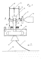
- a flexible lightweight cable 1 is lowered from a cable ship (not shown) into an upper funnel 2 of a cable guiding device 3.
- the cable 1 passes through a pipe 4 and leaves the pipe through a funnel 5 a short distance above the sea bed 19.
- the funnel 5 should be about 2-3m above the sea bed.
- the cable 1 may be laid on the sea bed itself or into a premade trench (not shown).
- the guiding device 3 is supported from the cable ship by means of one or two wires 6 and 7 and it is provided with a weight 8, the size of which is adapted to the type of cable to be laid, to the water depth and to the sea currents.
- the purpose of the combined weight of the guiding device is to ensure that the funnel 5 has a defined position relatively to the sea bed and that the pull in the cable laying on the sea bed is suitable.
- the weight may be constituted by blocks of concrete, stone or lead.
- the cable guiding means 3 may include electronic instrumentation 9, like video, gyro, sonar, altimeter and inclination equipment for controlling and recording the position of the cable 1.
- the instrumentation may also include means for controlling the relative position between the guiding means and a trenching device (14, Fig 3).
- the cable guiding means 3 may also include rudder means 10 and propeller means 11 for actively positioning the cable on the sea bed 19.
- the control signals and power for the electronic instrumentation and for the rudder/propeller may be supplied from the cable ship, via an umbilical cable 12 supported on one of the supporting wires 6,7. (In Figure 2 and 3 the supporting wire 7 is shown as an optional wire.)
- the cable 1 may also be guided from the ship to the funnel 2 by means of one or more guide rings 13 secured to either or both of the wires 6,7.
- the guiding means will be suitable for laying lightweight cables such as fibre optic cables at depths down to 1000m.
- the weight of such cables is in the order of 0.5 - 5 kg per meter length.
- the single layer armour results in a minimum bending diameter of 1.5m and the distance between the guide rings 13 should be relatively short to avoid coiling and kinking between the rings.
- the horizontal positioning requirements are ⁇ 1% of the laying depth, even with sea currents in the order of 2 knots.
- the total weight of the guiding means 3 may be in the order of 1,000 kg of which some 800 kg may be made up by the weight 8.
- FIG 2 is schematically illustrated how a cable 1 is lowered to the sea bed 19 by means of a guiding device 3
- Figure 3 is illustrated how the cable 1 can be lowered to the sea bed directly in front of a trenching device 14 to obtain simultaneous laying and trenching.
- the distance between the guiding means 3 and the trenching device 14 should be in the order of 10m but it could be longer.
- the trenching device is connected to the cable ship (not shown) by an umbilical device 15.
- the trenching device picks up the cable 1, fluidizes the sea bed, removes the gravel and lets the cable into a trench 16. If the distance between the laying position and the trenching position is more than, say 100m, it would be practical to use two different surface ships (not shown).
- the cable ship or ships move in the direction indicated with the arrows 17.
- a cable strain sensor and a declination meter may be used to control the speed of the cable ship(s) and in particular the positioning and installation of the rather sensitive fibre cable 1.
- the guiding means is suitable for laying a line along a predetermined path and for laying a line in a premade trench.
- the cable guiding means of the present invention also facilitates correction of the positioning of the cable during the laying process.
- Cable buffer or accumulator means 18 may be arranged as illustrated in Figure 2, between the cable ship and the guiding means 3, preferably right above the guiding means 3, for taking up possible slacks in the cable 1.
- the line guiding means of the present invention facilitates increased laying speed without the use of ROV's (remote controlled vehicles) or divers at sea depths down to 1000m and more. If trenching is not required the laying speed may be increased further.
- ROV's remote controlled vehicles
- the guiding means 3 may be removed or lifted to a higher position close to the ship bow. This situation may be preferred when the cable is installed in shallow parts of the cable path. In this case the cable will hang freely from the ship to the sea bed.
- the cable may also be positioned along a predetermined track by a diver or by a diving vessel. The cable may then also be guided directly to a trenching device.
Landscapes
- Physics & Mathematics (AREA)
- General Physics & Mathematics (AREA)
- Optics & Photonics (AREA)
- Laying Of Electric Cables Or Lines Outside (AREA)
Applications Claiming Priority (2)
| Application Number | Priority Date | Filing Date | Title |
|---|---|---|---|
| NO894057 | 1989-10-11 | ||
| NO89894057A NO894057L (no) | 1989-10-11 | 1989-10-11 | Kabel-legge-utstyr. |
Publications (1)
| Publication Number | Publication Date |
|---|---|
| EP0431279A1 true EP0431279A1 (de) | 1991-06-12 |
Family
ID=19892463
Family Applications (1)
| Application Number | Title | Priority Date | Filing Date |
|---|---|---|---|
| EP90119247A Withdrawn EP0431279A1 (de) | 1989-10-11 | 1990-10-08 | Vorrichtung zum Verlegen eines langen flexiblen Körpers, z.B. eines Faserkabels |
Country Status (2)
| Country | Link |
|---|---|
| EP (1) | EP0431279A1 (de) |
| NO (1) | NO894057L (de) |
Cited By (4)
| Publication number | Priority date | Publication date | Assignee | Title |
|---|---|---|---|---|
| EP0883009A3 (de) * | 1997-06-05 | 1999-09-29 | Alcatel | Installationsverfahren |
| GB2480688A (en) * | 2010-05-28 | 2011-11-30 | Acergy Norway As | A method of controlling subsea laying of an elongate article |
| EP2511996A1 (de) | 2011-04-15 | 2012-10-17 | Optoplan AS | Unterwasserkabelinstallationseinheit |
| GB2516375A (en) * | 2013-07-15 | 2015-01-21 | Green Theme Ltd | System, device and method for deploying and monitoring subsea cables |
Citations (3)
| Publication number | Priority date | Publication date | Assignee | Title |
|---|---|---|---|---|
| GB839546A (de) * | 1900-01-01 | |||
| GB955598A (en) * | 1959-07-29 | 1964-04-15 | Western Electric Co | Improvements in or relating to underwater lowering devices |
| FR2446551A1 (fr) * | 1979-01-10 | 1980-08-08 | Cables De Lyon Geoffroy Delore | Procede et dispositif d'ensouillement d'un cable sous-marin deja pose |
-
1989
- 1989-10-11 NO NO89894057A patent/NO894057L/no unknown
-
1990
- 1990-10-08 EP EP90119247A patent/EP0431279A1/de not_active Withdrawn
Patent Citations (3)
| Publication number | Priority date | Publication date | Assignee | Title |
|---|---|---|---|---|
| GB839546A (de) * | 1900-01-01 | |||
| GB955598A (en) * | 1959-07-29 | 1964-04-15 | Western Electric Co | Improvements in or relating to underwater lowering devices |
| FR2446551A1 (fr) * | 1979-01-10 | 1980-08-08 | Cables De Lyon Geoffroy Delore | Procede et dispositif d'ensouillement d'un cable sous-marin deja pose |
Non-Patent Citations (1)
| Title |
|---|
| JOURNAL OF ELECTRONIC ENGINEERING, vol. 24, no. 243, March 1987, pages 83-86, Tokyo, JP; Y. EJIRI: "A self-driven submarine cable burier" * |
Cited By (11)
| Publication number | Priority date | Publication date | Assignee | Title |
|---|---|---|---|---|
| EP0883009A3 (de) * | 1997-06-05 | 1999-09-29 | Alcatel | Installationsverfahren |
| GB2480688A (en) * | 2010-05-28 | 2011-11-30 | Acergy Norway As | A method of controlling subsea laying of an elongate article |
| WO2011147853A1 (en) | 2010-05-28 | 2011-12-01 | Subsea 7 Contracting (Norway) As | Subsea position control system for elongate articles |
| GB2480688B (en) * | 2010-05-28 | 2012-11-14 | Subsea 7 Contracting Norway As | Subsea position control system for elongate articles |
| AU2011257302A1 (en) * | 2010-05-28 | 2013-01-10 | Subsea 7 Norway As | Subsea position control system for elongate articles |
| AU2011257302B2 (en) * | 2010-05-28 | 2016-06-30 | Subsea 7 Norway As | Subsea position control system for elongate articles |
| US9863554B2 (en) | 2010-05-28 | 2018-01-09 | Subsea 7 Norway As | Subsea position control system for elongate articles |
| EP2511996A1 (de) | 2011-04-15 | 2012-10-17 | Optoplan AS | Unterwasserkabelinstallationseinheit |
| US10153626B2 (en) | 2011-04-15 | 2018-12-11 | Optoplan As | Subsea cable installation unit |
| GB2516375A (en) * | 2013-07-15 | 2015-01-21 | Green Theme Ltd | System, device and method for deploying and monitoring subsea cables |
| GB2516375B (en) * | 2013-07-15 | 2016-04-06 | Green Theme Ltd | System, device and method for deploying and monitoring subsea cables |
Also Published As
| Publication number | Publication date |
|---|---|
| NO894057L (no) | 1991-04-12 |
| NO894057D0 (no) | 1989-10-11 |
Similar Documents
| Publication | Publication Date | Title |
|---|---|---|
| US6350085B1 (en) | Cable deployment system and method of using same | |
| CN103247977B (zh) | 多相海底电缆横向布置循环敷设施工方法 | |
| EP2511996B1 (de) | Unterwasserkabelinstallationseinheit | |
| GB1107541A (en) | Laying an underwater pipeline from a floating vessel | |
| EP3436335B1 (de) | Verfahren zur installation einer unterwasserstruktur | |
| USRE28410E (en) | Tension pipe laying method | |
| US4041719A (en) | Method and apparatus for connecting submarine pipelines | |
| US3795114A (en) | Process and installation for the connection of a cable or flexible pipe to an underwater guide column | |
| US8282316B2 (en) | Method and assembly for installing oilfield equipment at the water bottom | |
| CN113644594A (zh) | 一种冲埋式的海缆敷设方法 | |
| JP4590442B2 (ja) | ケーブル等の長尺体を水底に敷設する装置 | |
| GB2206628A (en) | Method of installing a template on the seafloor | |
| US3702539A (en) | Method and apparatus for installing risers | |
| JP3743529B2 (ja) | 無人潜水機システム | |
| JPS5910128B2 (ja) | 可撓体の水中布設方法 | |
| BRPI0709636A2 (pt) | métodos para rebocar um scr e um oleoduto ao longo do leito do mar, para instalar um oleoduto de águas profundas em um dispositivo de ancoragem no leito do mar, para reboque de fundo e lançamento submerso de um tubo ascendente e para recuperar um tubo ascendente | |
| US4126013A (en) | Pipelaying under ice by bottom pull | |
| EP3835197A1 (de) | Installation einer leitung zwischen zwei strukturen | |
| JPH0261204B2 (de) | ||
| JPS5922443B2 (ja) | 水底ケ−ブルの布設方法 | |
| JP2791181B2 (ja) | 海底ケーブル布設同時埋設方法およびその装置 | |
| JPH11299035A (ja) | 海底ケーブル防護工法 | |
| EP4388235B1 (de) | Verfahren zum einsatz eines länglichen elements und spannsystem | |
| JPH06159553A (ja) | 水底沈設管布設方法 | |
| JPS63294205A (ja) | 海底ケ−ブルの敷設装置 |
Legal Events
| Date | Code | Title | Description |
|---|---|---|---|
| PUAI | Public reference made under article 153(3) epc to a published international application that has entered the european phase |
Free format text: ORIGINAL CODE: 0009012 |
|
| AK | Designated contracting states |
Kind code of ref document: A1 Designated state(s): BE DE DK ES FR GB IT NL SE |
|
| 17P | Request for examination filed |
Effective date: 19911202 |
|
| 17Q | First examination report despatched |
Effective date: 19930701 |
|
| STAA | Information on the status of an ep patent application or granted ep patent |
Free format text: STATUS: THE APPLICATION IS DEEMED TO BE WITHDRAWN |
|
| 18D | Application deemed to be withdrawn |
Effective date: 19931112 |