EP0431395A2 - Dispositif pour la mésure de la dureté de surface de matériaux de construction - Google Patents
Dispositif pour la mésure de la dureté de surface de matériaux de construction Download PDFInfo
- Publication number
- EP0431395A2 EP0431395A2 EP90122201A EP90122201A EP0431395A2 EP 0431395 A2 EP0431395 A2 EP 0431395A2 EP 90122201 A EP90122201 A EP 90122201A EP 90122201 A EP90122201 A EP 90122201A EP 0431395 A2 EP0431395 A2 EP 0431395A2
- Authority
- EP
- European Patent Office
- Prior art keywords
- hammer
- pattern
- scanning unit
- impact
- optical scanning
- Prior art date
- Legal status (The legal status is an assumption and is not a legal conclusion. Google has not performed a legal analysis and makes no representation as to the accuracy of the status listed.)
- Withdrawn
Links
Images


Classifications
-
- G—PHYSICS
- G01—MEASURING; TESTING
- G01N—INVESTIGATING OR ANALYSING MATERIALS BY DETERMINING THEIR CHEMICAL OR PHYSICAL PROPERTIES
- G01N3/00—Investigating strength properties of solid materials by application of mechanical stress
- G01N3/40—Investigating hardness or rebound hardness
- G01N3/52—Investigating hardness or rebound hardness by measuring extent of rebound of a striking body
Definitions
- the invention relates to a device for measuring the surface hardness of building materials, such as concrete, wherein a test hammer is provided which can be brought into contact with a firing pin by spring force and which rests on the test surface during the measurement, and a measuring device for determining the return path of the hammer is provided after the impact.
- Such a device has become known as a so-called Schmidthammer and is widely used today. Its basic principle is e.g. in CH-PS 283 099.
- a hammer is brought into contact with a firing pin by spring force, which is placed on the concrete surface.
- the firing pin which is rounded at the front, easily penetrates the concrete, which consumes part of the impact energy.
- the remaining energy then causes the hammer to rebound against the action of the striking spring.
- the return path of the hammer in percent of its forward path path from the start of the spring force to the impact on the firing pin
- This value R is a characteristic value for the elastic and plastic behavior of the concrete in layers near the surface.
- the compressive strength of the concrete can be deduced from the rebound value R under certain conditions. This is done with the help of empirical conversion or calibration curves agreed R-value is assigned a certain compressive strength.
- the upper end position of the trailing pointer then gives the return path, which can be read on a scale on the hammer housing.
- the trailing pointer on a pointer rod must have a defined frictional resistance when it is moved. This must e.g. lie between 50 g and 80 g, so that on the one hand the drag pointer does not fly beyond the return path and on the other hand the hammer is not excessively braked by the drag pointer. Mainly because of the contamination of the pointer rod, this defined frictional resistance has to be checked and readjusted very frequently. Another disadvantage is a relatively rough measurement reading, since the bar scale can only be divided relatively roughly for reasons of legibility.
- the reading and logging of the measured value must be carried out immediately after the test impact while the test hammer is still pressed firmly against the test site to prevent the drag pointer from being shifted before the reading. This is at least unwieldy and difficult with certain striking positions. Finally, automatic further processing of the measured values is not possible.
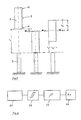
- Figure 1 is a sectional view of the device, partially schematically, in its initial position.
- FIG. 2 shows a sectional view as in FIG. 1, with the striking spring tensioned before the measurement
- FIGS. 1 and 2 shows a sectional view, as in FIGS. 1 and 2, with the hammer in the impact position;
- FIG 6 shows the block diagram of an evaluation circuit.
- FIGS. 1 to 3 The mechanical structure of the measuring device will first be briefly explained with reference to FIGS. 1 to 3.
- an operating phase of the device is shown, namely in FIG. 1 the initial state, in FIG. 2 the clamping state immediately before the measurement is triggered and in FIG. 3 the state after the measurement.
- the device has a hammer 5 which can be accelerated against a firing pin 3 by the force of a striking spring 11 designed as a tension spring.
- the firing pin 3 is slidably held in a guide sleeve 13 which is arranged at the front on the housing 1 of the device.
- a running rod 4 At the rear of the firing pin 3 there is a running rod 4 on which the hammer 5 is guided.
- the running rod 4 also carries a guide disk 6, which acts as an anti-rotation device, and a pawl 7, which engages in the hammer 5 for tensioning the striking spring 11 until it is opened by bumping on the housing cover 2, thereby triggering a measurement shock (see FIG . 2).
- a compression spring 10 designed as a compression spring, which presses the pawl 7, together with the running rod and the firing pin 3, after each measurement into its front starting position (FIG. 1), where it is again tensioned in the hammer 5 intervenes.
- This structure corresponds to that of the already known concrete testing devices and therefore does not need to be described in more details.
- the hammer 5 is now provided with an optical pattern 8 on its cylindrical outer surface over its length.
- Such a pattern essentially consists of successive, equally wide strips on the hammer surface, which are alternately light-reflecting and non-light-reflecting.
- groove-like depressions 9 with light-absorbing coloring follow and non-recessed jacket zones 16 with a reflective coating.
- the grooves are shown only schematically in FIG. 1.
- the zone or groove width is much smaller, e.g. 0.40 mm, and a total of approximately 29 grooves 9 or 30 reflecting zones 16 are provided. It is advantageous not to make the pattern much finer in order to ensure perfect optical detection even when dirty.
- the measurement accuracy can, however, go significantly below the fineness of the pattern by means of interpolation, as will be explained below.
- An infrared light transmitter / sensor 12 is provided on the housing 1 as an optical scanning unit. At the point indicated by an arrow 21 there is a slit diaphragm running transversely to the direction of movement of the hammer, the position of which determines the zero point of measurement. Through this slit diaphragm, the pattern is illuminated by an infrared diode at a certain angle of incidence. An infrared light sensor is arranged at the angle of reflection, in which the reflected through the slit diaphragm Infrared light is converted into an electrical signal.
- the sensor “sees” alternately light and dark, with which the number of strips of the pattern that have moved through in front of the scanning unit can be counted.
- the return path can be determined on the basis of this signal, as will be explained in more detail.
- the stripes are not merely counted, but rather if a time is measured for each stripe of the pattern which essentially corresponds to the time during which a reflection signal (or no signal) is received through the slit diaphragm .
- a time counter is provided for this, which is started as soon as the light sensor sees “bright”. The counter runs as long as the light sensor sees “bright”. As soon as it sees "dark”, the counter is stopped and practically restarted at the same time. The counter is thus - except for the first start - always stopped and restarted at the end of each light and dark stripe.
- a Schmitt trigger 22 which is connected to the sensor 21 and whose operating point lies approximately at the zero crossing of the wave-shaped sensor signal, serves to trigger the counter. In this way, a separate count is generated and saved for each strip of the pattern. As a result, the count results are available as a measurement result and can be used as a basis for further evaluation.
- the circuit is indicated in FIG. 6, in which the light sensor 21 is connected via a Schmitt trigger 22 to a microcomputer 23 acting as a counter, which also ensures the storage and evaluation of the count status sequences.
- the R value determined in this way is output via a display unit 24.
- the position of the light sensor 21 is indicated by an arrow.
- the path h R1 is therefore the hammer's return path measured by the light sensor.
- the real return path is only obtained by adding an adjustment variable a to the value h R1 .
- the adjustment variable a depends on the mounting location of the sensor 21 on the housing and can be adjusted by time measurement, as will be described.
- the pattern 8 on the hammer 5 is delimited on both sides by a reflecting zone 14, 15 of greater width. These zones are preferably about three times the size of the remaining strips of the pattern. This ensures reliable triggering of the start-stop counter at the beginning or end of hammer 5 even if these parts e.g. are damaged or inadvertently soiled due to repeated installation and removal of the hammer for maintenance purposes.
- the hammer 5 After triggering the blow, the hammer 5 first moves down past the sensor 21. This creates a signal pattern of successive 30 "light” and 29 “dark” signals (time counts), the first and the last "light” signal being significantly longer than the adjacent signals. If this signal pattern is not determined in this first phase of the measurement, ie the impact phase, this indicates an error in the device towards, for example, contamination of the optical pattern, which means that it is no longer possible to correctly measure the return path. In such cases, therefore, the measurement is rejected by the evaluation circuit. Otherwise the subsequent measurement of the return path is accepted.
- the speed of the hammer upon impact and thus the impact energy can be measured and continuously monitored from the partial count times during the impact phase close to the impact. This ensures that the measurement always takes place within a standardized range of the impact energy, otherwise the device (in particular the striking spring 11) must be checked.
- the sensor 21 does not "see” the hammer 5 shortly before and also shortly after the impact.
- This time between the end of the last (longer) "light” signal and the beginning of the same "light” signal in the opposite direction of movement is measured as the reversal time T u .
- T u the reversal time
- the maximum of the time counting periods thus essentially corresponds to the upper reversal point at the end the return path. If it is now determined where this maximum occurs in the sequence of time counter signals received on the return, the corresponding position on the pattern 8 can be assigned to the signal sequence, whereby the return path h R1 of the hammer 5 is determined.
- the subdivision of the pattern 8 is not chosen too finely in order not to make the optical scanning susceptible to contamination.
- an interpolation can be carried out on the basis of the measured time counter values to determine the exact reversal point at the end of the return path.
- FIG. 5 schematically plots the time count values of five fictitious impact tests with a maximum time count value, which is approximately at strip No. 7, in five diagrams. On the vertical axis of each diagram, the respective count value is given, which belongs to each of the horizontally plotted strip numbers.
- strip No. 7 is just not yet reached, while in the diagrams that follow below, an increasing height is reached in the region of strip No. 7, as can be seen from the increasing time count values.
- the entire strip width ie 0.40 mm, is detected by the sensor.
- Interpolation can now be carried out in accordance with the time counts for strip No. 7 in comparison to the neighboring time counts.
- a suitable interpolation measure is, for example, the quotient of the time count in the area to be interpolated (strip No. 7) to the time count of the neighboring area (eg strip No. 8). From this quotient Q, the fraction of the stripe width at the end of the return path can be determined by an empirical, stored interpolation curve, which is still detected by the sensor has been.
- other numerical interpolation methods could also be used.
- the return path can thus be measured with much greater accuracy than corresponds to the division of the optical pattern on the hammer 5.
- Another advantageous consequence of the time counts explained about the individual “light” and “dark” stripes of the pattern is that the light-dark contrast of the pattern can be monitored with this, namely by forming the quotient between the light and dark times T LIGHT / T DARK . If this quotient is about 1, the contrast is good. If the dark times increase, ie if the quotient is significantly smaller than 1, this indicates a decreasing contrast, ie a contamination of the optical pattern. The user is prompted to clean the optical pattern when a certain minimum value is reached.
- the device described it is possible to achieve flawless, exact measurements of the rebound value R despite the harsh operating conditions.
- the strong mechanical shocks and vibrations during impact do not have any negative effects on the contactless measurement.
- the effects of contamination caused by concrete dust and internal abrasion in the device can also be controlled with the measures described.
Landscapes
- Physics & Mathematics (AREA)
- Health & Medical Sciences (AREA)
- Life Sciences & Earth Sciences (AREA)
- Chemical & Material Sciences (AREA)
- Analytical Chemistry (AREA)
- Biochemistry (AREA)
- General Health & Medical Sciences (AREA)
- General Physics & Mathematics (AREA)
- Immunology (AREA)
- Pathology (AREA)
- Investigating Strength Of Materials By Application Of Mechanical Stress (AREA)
- Investigating Or Analyzing Materials By The Use Of Ultrasonic Waves (AREA)
Applications Claiming Priority (2)
| Application Number | Priority Date | Filing Date | Title |
|---|---|---|---|
| CH4397/89A CH679953A5 (fr) | 1989-12-07 | 1989-12-07 | |
| CH4397/89 | 1989-12-07 |
Publications (2)
| Publication Number | Publication Date |
|---|---|
| EP0431395A2 true EP0431395A2 (fr) | 1991-06-12 |
| EP0431395A3 EP0431395A3 (en) | 1992-02-19 |
Family
ID=4275373
Family Applications (1)
| Application Number | Title | Priority Date | Filing Date |
|---|---|---|---|
| EP19900122201 Withdrawn EP0431395A3 (en) | 1989-12-07 | 1990-11-20 | Apparatus for measuring the surface hardness of construction materials |
Country Status (7)
| Country | Link |
|---|---|
| US (1) | US5176026A (fr) |
| EP (1) | EP0431395A3 (fr) |
| JP (1) | JPH03211443A (fr) |
| CA (1) | CA2031711A1 (fr) |
| CH (1) | CH679953A5 (fr) |
| FI (1) | FI905882L (fr) |
| NO (1) | NO905286L (fr) |
Cited By (8)
| Publication number | Priority date | Publication date | Assignee | Title |
|---|---|---|---|---|
| AT801U1 (de) * | 1995-06-27 | 1996-05-28 | Schmiedmayer Robert Dipl Ing | Mörtelprüfgerät |
| WO1996034267A1 (fr) * | 1995-04-27 | 1996-10-31 | Krautkrämer Gmbh & Co. | Procede pour l'essai de durete de pieces et dispositif pour sa mise en ×uvre |
| FR2760842A1 (fr) * | 1997-03-14 | 1998-09-18 | Sarl Mercure Innovation | Dispositif de mesure, de controle et d'enregistrement des caracteristiques d'un element en bois |
| DE19743119C1 (de) * | 1997-09-30 | 1998-11-12 | Deutsche Telekom Ag | Verfahren zur Überprüfung der Standsicherheit von Leitungsmasten aus Holz |
| ITRM20090226A1 (it) * | 2009-05-08 | 2009-08-07 | Federazione Italiana Bocce | Apparecchio per la misurazione del rimbalzo e della scorrevolezza delle corsie di gioco |
| CN109115592A (zh) * | 2018-08-28 | 2019-01-01 | 深圳市必发达科技有限公司 | 一种混凝土回弹仪 |
| RU2725902C1 (ru) * | 2019-12-09 | 2020-07-07 | Федеральное государственное бюджетное образовательное учреждение высшего образования «Брянский государственный технический университет» | Способ определения твердости композиционных гетерогенных материалов |
| CN116297668A (zh) * | 2023-05-17 | 2023-06-23 | 新乡职业技术学院 | 一种建筑材料综合性能检测设备 |
Families Citing this family (19)
| Publication number | Priority date | Publication date | Assignee | Title |
|---|---|---|---|---|
| US5841019A (en) * | 1997-07-14 | 1998-11-24 | Drabrin; Sergey | Method for non-destructive measuring compressive and tensile strengths of concrete in the structure |
| US6158272A (en) * | 1999-03-23 | 2000-12-12 | Berretta; Dominic | Tester for structural integrity of building materials and method |
| EP1893973B1 (fr) * | 2005-06-24 | 2010-06-23 | Marco Brandestini | Appareil destine a la mesure de durete par impact |
| CN101802585B (zh) * | 2007-09-20 | 2012-03-21 | 马尔科·布兰德斯蒂尼 | 无损测量固体耐压强度的方法和装置 |
| WO2009079959A1 (fr) * | 2007-12-19 | 2009-07-02 | Shengye Tang | Procédé pour acquérir une valeur de rebond, tester un résiliomètre et étalonner un détecteur |
| KR101238388B1 (ko) * | 2010-03-29 | 2013-02-28 | 김옥환 | 압축강도 측정기 |
| CN102539262B (zh) * | 2011-12-23 | 2014-04-09 | 舟山市博远科技开发有限公司 | 高强混凝土回弹仪的使用方法 |
| US9931218B2 (en) | 2012-10-30 | 2018-04-03 | Biomet Manufacturing, Llc | Method of implanting a knee prosthesis based on bone density |
| CN103018119A (zh) * | 2012-12-05 | 2013-04-03 | 中电投工程研究检测评定中心 | 一种防水层检测装置 |
| US9404848B2 (en) * | 2014-03-11 | 2016-08-02 | The Boeing Company | Apparatuses and methods for testing adhesion of a seal to a surface |
| EP3028821A1 (fr) * | 2014-12-03 | 2016-06-08 | HILTI Aktiengesellschaft | Procédé de contrôle pour une machine-outils portative |
| CN108007764B (zh) * | 2017-12-29 | 2023-12-29 | 上海勘察设计研究院(集团)股份有限公司 | 下埋式混凝土构件强度非开挖检测装置及其方法 |
| CN108645700B (zh) * | 2018-05-31 | 2020-10-20 | 苏州市吴江东南建筑检测有限公司 | 一种混凝土回弹仪及其使用方法 |
| CN109342235B (zh) * | 2018-11-30 | 2021-07-09 | 湖南长建科技有限公司 | 一种混凝土回弹参数检测装置及检测方法 |
| CN110068515A (zh) * | 2019-05-21 | 2019-07-30 | 湖州华科建设工程质量检测有限公司 | 一种建设工程用多功能检测器 |
| CN110823736A (zh) * | 2019-11-18 | 2020-02-21 | 无锡市前友工程咨询检测有限公司 | 一种混凝土回弹仪自动打点装置 |
| CN113092297B (zh) * | 2021-04-30 | 2024-03-29 | 安徽宏基建设项目管理有限公司 | 一种建筑结构多功能检测仪 |
| CN113982046B (zh) * | 2021-10-28 | 2023-06-06 | 深圳市勘察研究院有限公司 | 一种自动落锤激振器 |
| CN115808425B (zh) * | 2023-01-30 | 2023-05-05 | 安徽新建控股集团有限公司 | 在混凝土构件回弹检测过程中的缺陷识别和应对方法 |
Family Cites Families (11)
| Publication number | Priority date | Publication date | Assignee | Title |
|---|---|---|---|---|
| US2948890A (en) * | 1956-04-26 | 1960-08-09 | Dell Brothers O | Position meter |
| US3576127A (en) * | 1969-10-20 | 1971-04-27 | Daniel H Weitzel | Resilience testing device |
| US3669261A (en) * | 1970-03-19 | 1972-06-13 | Hughes Aircraft Co | Hardness testing machine |
| US3879982A (en) * | 1972-10-16 | 1975-04-29 | Ernst Schmidt | Method and apparatus for testing hardness of specimens |
| SU978010A1 (ru) * | 1981-06-11 | 1982-11-30 | Специальное Конструкторское Бюро Научно-Производственного Объединения "Нефтехимавтоматика" | Устройство дл определени эластичности резин |
| DE3428805A1 (de) * | 1984-08-04 | 1986-02-13 | Bopp & Reuther Gmbh, 6800 Mannheim | Pruefeinrichtung fuer durchflussmesser |
| US4674317A (en) * | 1985-07-19 | 1987-06-23 | Flow Technology | Apparatus for determining the flow characteristic of a volumetric flowmeter |
| JPS631950A (ja) * | 1986-06-23 | 1988-01-06 | Japan Synthetic Rubber Co Ltd | 反発試験装置 |
| US4786803A (en) * | 1987-06-01 | 1988-11-22 | Hewlett-Packard Company | Single channel encoder with specific scale support structure |
| US4885933A (en) * | 1988-05-24 | 1989-12-12 | The Upjohn Company | Hardness impact tester |
| US5047629A (en) * | 1990-03-30 | 1991-09-10 | Motorola, Inc. | Position and motion detector with magnetic coupling and optical detection |
-
1989
- 1989-12-07 CH CH4397/89A patent/CH679953A5/de not_active IP Right Cessation
-
1990
- 1990-11-20 EP EP19900122201 patent/EP0431395A3/de not_active Withdrawn
- 1990-11-29 FI FI905882A patent/FI905882L/fi not_active Application Discontinuation
- 1990-11-29 JP JP2333471A patent/JPH03211443A/ja active Pending
- 1990-12-05 US US07/622,844 patent/US5176026A/en not_active Expired - Fee Related
- 1990-12-06 NO NO90905286A patent/NO905286L/no unknown
- 1990-12-06 CA CA002031711A patent/CA2031711A1/fr not_active Abandoned
Cited By (8)
| Publication number | Priority date | Publication date | Assignee | Title |
|---|---|---|---|---|
| WO1996034267A1 (fr) * | 1995-04-27 | 1996-10-31 | Krautkrämer Gmbh & Co. | Procede pour l'essai de durete de pieces et dispositif pour sa mise en ×uvre |
| AT801U1 (de) * | 1995-06-27 | 1996-05-28 | Schmiedmayer Robert Dipl Ing | Mörtelprüfgerät |
| FR2760842A1 (fr) * | 1997-03-14 | 1998-09-18 | Sarl Mercure Innovation | Dispositif de mesure, de controle et d'enregistrement des caracteristiques d'un element en bois |
| DE19743119C1 (de) * | 1997-09-30 | 1998-11-12 | Deutsche Telekom Ag | Verfahren zur Überprüfung der Standsicherheit von Leitungsmasten aus Holz |
| ITRM20090226A1 (it) * | 2009-05-08 | 2009-08-07 | Federazione Italiana Bocce | Apparecchio per la misurazione del rimbalzo e della scorrevolezza delle corsie di gioco |
| CN109115592A (zh) * | 2018-08-28 | 2019-01-01 | 深圳市必发达科技有限公司 | 一种混凝土回弹仪 |
| RU2725902C1 (ru) * | 2019-12-09 | 2020-07-07 | Федеральное государственное бюджетное образовательное учреждение высшего образования «Брянский государственный технический университет» | Способ определения твердости композиционных гетерогенных материалов |
| CN116297668A (zh) * | 2023-05-17 | 2023-06-23 | 新乡职业技术学院 | 一种建筑材料综合性能检测设备 |
Also Published As
| Publication number | Publication date |
|---|---|
| NO905286D0 (no) | 1990-12-06 |
| FI905882A7 (fi) | 1991-06-08 |
| CH679953A5 (fr) | 1992-05-15 |
| NO905286L (no) | 1991-06-10 |
| FI905882L (fi) | 1991-06-08 |
| JPH03211443A (ja) | 1991-09-17 |
| FI905882A0 (fi) | 1990-11-29 |
| US5176026A (en) | 1993-01-05 |
| CA2031711A1 (fr) | 1991-06-08 |
| EP0431395A3 (en) | 1992-02-19 |
Similar Documents
| Publication | Publication Date | Title |
|---|---|---|
| EP0431395A2 (fr) | Dispositif pour la mésure de la dureté de surface de matériaux de construction | |
| EP0761585B1 (fr) | Détecteur de fil | |
| EP0503040A1 (fr) | Dispositif capteur optique et son procede d'exploitation. | |
| DE2532603C3 (de) | Optische Vorrichtung zur Bestimmung des Lichtaustrittswinkels | |
| DE2532602B2 (de) | Optische Vorrichtung mit einem Lichtvorhang | |
| DE19544632A1 (de) | Optoelektronische Vorrichtung zum Erfassen von Objekten in einem Überwachungsbereich | |
| DE2550814B2 (de) | Zeilentastvorrichtung für Materialbahnen zur Fehlstellenermittlung | |
| DE3544871C2 (fr) | ||
| DE69115246T2 (de) | Vorrichtung und verfahren zum erlangen der mechanische eigenschaften von münzen. | |
| DE10039765A1 (de) | Vorrichtung zur Bestimmung der Füllhöhe eines Füllmediums in einem Tank | |
| DE3422772C2 (de) | Vorrichtung zur berührungslosen Innengewindemessung | |
| DE3644866A1 (de) | Sensor | |
| CH643614A5 (de) | Elektronischer schussfadenwaechter. | |
| EP0725374B1 (fr) | Contrôleur de pièces de monnaie avec dispositif pour vérifier la dureté | |
| WO2013131198A1 (fr) | Tête de mesure pour essai de fil | |
| CH646255A5 (de) | Verfahren zur automatischen auswertung von eindruecken bei der haertepruefung von werkstoffen und einrichtung zur durchfuehrung des verfahrens. | |
| WO2001019714A1 (fr) | Procede et dispositif de controle optique de la surface d'une bobine de fil | |
| DE2251915A1 (de) | Vorrichtung zum feststellen von flekken oder fehlern in einer oberflaeche | |
| DE2100046A1 (de) | Verfahren und Vorrichtung zur Ermittlung von Oberflächenfehlern bahnförmiger Materialien | |
| DD243518A1 (de) | Anordnung zur signalbeeinflussung in optoelektronischen mess- und ueberwachungsgeraeten, vorzugsweise fuer textile flaechengebilde, faeden und arbeitselemente an textilmaschinen | |
| DE102020201976B4 (de) | Vorrichtung und Verfahren zur optischen Analyse eines reflektierenden Prüflings | |
| DE29521575U1 (de) | Optoelektronische Vorrichtung zum Erkennen von Objekten in einem Überwachungsbereich | |
| DE19805207C2 (de) | Verfahren zur Bestimmung einer Bewegungsrichtung | |
| CH646521A5 (de) | Verfahren und vorrichtung zum nachweis feinster oberflaechenerhabenheiten an einem drahtfoermigen koerper, der einen ueberzug aus isolierlack besitzt. | |
| DE2522988A1 (de) | Schaltungsanordnung zur feststellung von fehlern |
Legal Events
| Date | Code | Title | Description |
|---|---|---|---|
| PUAI | Public reference made under article 153(3) epc to a published international application that has entered the european phase |
Free format text: ORIGINAL CODE: 0009012 |
|
| AK | Designated contracting states |
Kind code of ref document: A2 Designated state(s): AT BE DE DK ES FR GB IT NL SE |
|
| PUAL | Search report despatched |
Free format text: ORIGINAL CODE: 0009013 |
|
| AK | Designated contracting states |
Kind code of ref document: A3 Designated state(s): AT BE DE DK ES FR GB IT NL SE |
|
| 17P | Request for examination filed |
Effective date: 19920731 |
|
| 17Q | First examination report despatched |
Effective date: 19940307 |
|
| STAA | Information on the status of an ep patent application or granted ep patent |
Free format text: STATUS: THE APPLICATION IS DEEMED TO BE WITHDRAWN |
|
| 18D | Application deemed to be withdrawn |
Effective date: 19950829 |