EP0431420A2 - Redresseur à haut courant - Google Patents
Redresseur à haut courant Download PDFInfo
- Publication number
- EP0431420A2 EP0431420A2 EP90122424A EP90122424A EP0431420A2 EP 0431420 A2 EP0431420 A2 EP 0431420A2 EP 90122424 A EP90122424 A EP 90122424A EP 90122424 A EP90122424 A EP 90122424A EP 0431420 A2 EP0431420 A2 EP 0431420A2
- Authority
- EP
- European Patent Office
- Prior art keywords
- current
- supply line
- line
- semiconductor valves
- current rectifier
- Prior art date
- Legal status (The legal status is an assumption and is not a legal conclusion. Google has not performed a legal analysis and makes no representation as to the accuracy of the status listed.)
- Withdrawn
Links
Images

Classifications
-
- H—ELECTRICITY
- H10—SEMICONDUCTOR DEVICES; ELECTRIC SOLID-STATE DEVICES NOT OTHERWISE PROVIDED FOR
- H10W—GENERIC PACKAGES, INTERCONNECTIONS, CONNECTORS OR OTHER CONSTRUCTIONAL DETAILS OF DEVICES COVERED BY CLASS H10
- H10W90/00—Package configurations
-
- H—ELECTRICITY
- H10—SEMICONDUCTOR DEVICES; ELECTRIC SOLID-STATE DEVICES NOT OTHERWISE PROVIDED FOR
- H10W—GENERIC PACKAGES, INTERCONNECTIONS, CONNECTORS OR OTHER CONSTRUCTIONAL DETAILS OF DEVICES COVERED BY CLASS H10
- H10W42/00—Arrangements for protection of devices
- H10W42/80—Arrangements for protection of devices protecting against overcurrent or overload, e.g. fuses or shunts
Definitions
- the AC supply line is designed as a "hub” and connected in the form of a spoke to a "rim".
- the rim can be circular or polygonal, for example hexagonal.
- the semiconductor valves are attached to the rim and represent the link between the spokes and the rim, so that the current via the hub, the spokes and the semiconductor valves is rectified towards the rim.
- the direct current is then dissipated on the rim using a tangentially attached busbar.
- the object of the invention is to improve the current distribution of "wheel” rectifiers.
- a coaxial arrangement is particularly advantageous because of the symmetrical electrical fields. Since both current conductors are located, so to speak, as a hub construction in the middle of the "wheel” rectifier, almost the same current path and the same commutation inductances result for all semiconductor valve arrangements. If the heat sinks are also arranged in the form of a polygon, in particular a hexagon, with the AC supply line and the DC current derivation forming the center of the polygon, then the semiconductor valves can be easily attached to the heat sinks and connected to the coaxial power supply and discharge lines. In addition, the cooling bodies, which are then designed in a flat manner, can be provided in a simple manner with cooling devices such as fins or cooling plates.
- the heat sink can also be designed as a circular ring which is connected to the AC supply line or the DC power supply line via, for example, spoke-shaped supply lines.
- the expert can decide in individual cases which of the current conductors of the jacket-shaped or coaxial arrangement is used as an alternating current supply or direct current derivation.
- the cross-sectional areas of the inner and outer conductors can be adapted to the respective performance requirements.
- a respective semiconductor valve can advantageously be provided with a cooling box and a fuse on at least one pole.
- the cooling sockets and other elements contributing to cooling, for example the heat sinks, can additionally be connected to a liquid cooling circuit.
- the direct current supply G is designed as an outer conductor of the coaxial arrangement.
- the AC supply line W is designed as a tubular current conductor, for example in the form of an aluminum tube.
- the current conductor could also be rod-shaped.
- the DC discharge line G is connected to the corners of a hexagon via the spoke-shaped supply lines SG.
- the hexagon is formed from heat sinks K1, K2 ... which are connected to one another at their ends.
- the semiconductor valves D are arranged on the inside of the heat sinks K1, K2. Not only can two semiconductor valves D be attached to a heat sink K1, K2, as can be seen in FIG. 1, but depending on the height of the heat sink K1, K2, ie how far it extends into the drawing plane, several of the Semiconductor valves can be mounted one above the other.
- the semiconductor valves D can be controlled or uncontrolled semiconductor valves.
- they are designed as so-called disk diodes or disk thyristors.
- so-called screw rectifiers could also be used, for example, which could be attached to the heat sink K1, K2 with their screw thread.
- Cooling sockets KD are mounted on the semiconductor valves D, which can have cooling channels through which a cooling liquid is pumped. These cooling sockets KD can be connected to the heat sink K1, K2 by means of insulated screw bolts in such a way that the semiconductor valves D in between are clamped under pressure.
- the cooling sockets KD are connected via angular conductors L to one pole of fuses SI.
- the other pole of the fuses SI is connected to spoke-shaped supply lines SW leading away from the AC supply line W.
- each current branch between the AC power supply line W and the DC power supply line G thus consists of a spoke-shaped supply line SG, part of a heat sink K1, K2, a semiconductor valve D, a cooling box KD, an angled current conductor L, a fuse SI and a spoke-shaped one SW supply line.
- the remaining Different current paths that result when the direct current is taken, for example, tangentially from the direct current derivative G, are very much smaller than the different current paths that result when the direct current on the periphery, ie in the example in FIG. 1, on a heat sink K1 , K2 would be removed.
- This arrangement results in approximately the same inductances and thus the same commutation areas for each current path.
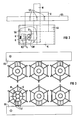
- FIG. 2 shows a possible front view of a high current rectifier according to FIG.
- a DC busbar is welded to the DC arrester G by means of three lamellar webs ST.
- the circular cylindrical direct current derivative G does not extend all the way into the center of the hexagonal arrangement from the heat sinks K.
- the AC supply line W extends just up to the lower end of the heat sink K1, K2.
- a spoke-shaped supply line SW can be seen inside the arrangement, which can be welded to the AC supply line W, for example.
- Two fuses SI are attached to the supply line SW and are connected to the diode D via two lines L and a cooling socket KD. The other pole of the diode D is connected to the heat sink K1, K2.
- FIG. 3 shows an arrangement with hexagonal "wheel” rectifiers, three of these rectifiers each being connected to a DC busbar GS.
- the AC power supply W is also designed as a circular cylinder this time.
- the DC busbars GS are each connected to a hexagonal rectifier arrangement via three lamellar webs ST. The entire arrangement can be attached so that one perpendicular to the arrangement in front seen air flow contributes fully or partially to cooling.
- the direct current lead G and / or the alternating current lead W do not necessarily have to have a circular cross section. You can have any cross-section, for example, like the heat sink arrangement, a polygonal cross-section.
Landscapes
- Rectifiers (AREA)
Applications Claiming Priority (2)
| Application Number | Priority Date | Filing Date | Title |
|---|---|---|---|
| DE3940637 | 1989-12-08 | ||
| DE3940637 | 1989-12-08 |
Publications (2)
| Publication Number | Publication Date |
|---|---|
| EP0431420A2 true EP0431420A2 (fr) | 1991-06-12 |
| EP0431420A3 EP0431420A3 (en) | 1991-08-14 |
Family
ID=6395089
Family Applications (1)
| Application Number | Title | Priority Date | Filing Date |
|---|---|---|---|
| EP19900122424 Withdrawn EP0431420A3 (en) | 1989-12-08 | 1990-11-23 | High current rectifier |
Country Status (1)
| Country | Link |
|---|---|
| EP (1) | EP0431420A3 (fr) |
Cited By (3)
| Publication number | Priority date | Publication date | Assignee | Title |
|---|---|---|---|---|
| US5498907A (en) * | 1993-04-29 | 1996-03-12 | Allied Signal Inc. | Interconnection arrangement for power semiconductor switching devices |
| CN101814844A (zh) * | 2010-04-13 | 2010-08-25 | 汪槱生 | 利用辅助桥反馈实现电流分配的三相整流器 |
| EP4518134A4 (fr) * | 2022-04-29 | 2025-07-23 | Denso Corp | Dispositif de conversion de puissance |
Family Cites Families (3)
| Publication number | Priority date | Publication date | Assignee | Title |
|---|---|---|---|---|
| DE1086349C2 (de) * | 1958-07-10 | 1961-11-02 | Siemens Ag | Stromrichteranlage fuer hohe Stroeme mit Halbleiterventilanordnungen |
| NL246646A (fr) * | 1959-01-31 | 1900-01-01 | ||
| US3902774A (en) * | 1974-08-22 | 1975-09-02 | Westinghouse Electric Corp | Force equalizing system |
-
1990
- 1990-11-23 EP EP19900122424 patent/EP0431420A3/de not_active Withdrawn
Cited By (4)
| Publication number | Priority date | Publication date | Assignee | Title |
|---|---|---|---|---|
| US5498907A (en) * | 1993-04-29 | 1996-03-12 | Allied Signal Inc. | Interconnection arrangement for power semiconductor switching devices |
| CN101814844A (zh) * | 2010-04-13 | 2010-08-25 | 汪槱生 | 利用辅助桥反馈实现电流分配的三相整流器 |
| CN101814844B (zh) * | 2010-04-13 | 2012-06-27 | 汪槱生 | 利用辅助桥反馈实现电流分配的三相整流器 |
| EP4518134A4 (fr) * | 2022-04-29 | 2025-07-23 | Denso Corp | Dispositif de conversion de puissance |
Also Published As
| Publication number | Publication date |
|---|---|
| EP0431420A3 (en) | 1991-08-14 |
Similar Documents
| Publication | Publication Date | Title |
|---|---|---|
| DE2304935A1 (de) | Rotierende gleichrichteranordnung | |
| DE2354663A1 (de) | Stromrichter | |
| DE3711192A1 (de) | Lager- und kuehleinrichtung fuer gleichrichterdioden bei elektrischen maschinen | |
| DE1614640B1 (de) | Gleichrichteranordnung | |
| DE1488761B2 (de) | Anordnung rotierender Gleichrichter | |
| EP0185181A1 (fr) | Circuit à anode-cathode à inductance réduite d'un thyristor GTO de puissance | |
| DE4023687C2 (de) | Stromrichteranordnung | |
| DE2056516A1 (de) | Anordnung von rotierenden Gleich nchtern zur burstenlosen Erregung elek frischer Maschinen | |
| EP0431420A2 (fr) | Redresseur à haut courant | |
| DE3533065A1 (de) | Adapter fuer einen drehstromgenerator | |
| WO2020224777A1 (fr) | Dissipateur thermique | |
| DE10204157B4 (de) | Drahtbondverbindung für Leistungshalbleiterbauelemente | |
| DE1489946A1 (de) | Festkoerper-Leistungsgleichrichter | |
| DE8801086U1 (de) | Verspanneinrichtung zum Kontaktieren elektrischer Hochstromleiter | |
| DE3931570C2 (de) | Anordnung des Kühlwasserkreislaufs im Gleichstromkreis eines Stromrichters | |
| AT222759B (de) | Gleichrichtergerät mit Halbleiterzellen | |
| DE3529182A1 (de) | Hochstrom-gleichrichteranlage mit halbleiterventilen | |
| DE3206388A1 (de) | Anordnung fuer eine rotierende thyristorerregung | |
| DE3940892A1 (de) | Gleichrichteranlage mit halbleiterventilanordnungen | |
| DE1514225B2 (de) | Anordnung von Halbleitergleichrichtern auf einer rotierenden Welle | |
| EP0513416B1 (fr) | Elément de connexion de câble, construction coaxiale, a faible champ de fuit | |
| DE1439239A1 (de) | Hochstrom-Gleichrichteranlage | |
| DE1301853B (de) | Hochleistungssicherung | |
| DE1614640C (de) | Gleichrichteranordnung | |
| DE1489946C (de) | Gleichrichter-Anordnung |
Legal Events
| Date | Code | Title | Description |
|---|---|---|---|
| PUAI | Public reference made under article 153(3) epc to a published international application that has entered the european phase |
Free format text: ORIGINAL CODE: 0009012 |
|
| 17P | Request for examination filed |
Effective date: 19901205 |
|
| AK | Designated contracting states |
Kind code of ref document: A2 Designated state(s): CH DE FR LI SE |
|
| PUAL | Search report despatched |
Free format text: ORIGINAL CODE: 0009013 |
|
| AK | Designated contracting states |
Kind code of ref document: A3 Designated state(s): CH DE FR LI SE |
|
| 17Q | First examination report despatched |
Effective date: 19930510 |
|
| STAA | Information on the status of an ep patent application or granted ep patent |
Free format text: STATUS: THE APPLICATION IS DEEMED TO BE WITHDRAWN |
|
| 18D | Application deemed to be withdrawn |
Effective date: 19930924 |