EP0431426A1 - Procédé et installation pour opérer une centrifugeuse filtrante - Google Patents
Procédé et installation pour opérer une centrifugeuse filtrante Download PDFInfo
- Publication number
- EP0431426A1 EP0431426A1 EP90122453A EP90122453A EP0431426A1 EP 0431426 A1 EP0431426 A1 EP 0431426A1 EP 90122453 A EP90122453 A EP 90122453A EP 90122453 A EP90122453 A EP 90122453A EP 0431426 A1 EP0431426 A1 EP 0431426A1
- Authority
- EP
- European Patent Office
- Prior art keywords
- time
- centrifuge
- change
- determined
- dry
- Prior art date
- Legal status (The legal status is an assumption and is not a legal conclusion. Google has not performed a legal analysis and makes no representation as to the accuracy of the status listed.)
- Granted
Links
- 238000000034 method Methods 0.000 title claims abstract description 28
- 238000009434 installation Methods 0.000 title 1
- 239000012065 filter cake Substances 0.000 claims abstract description 33
- 239000007788 liquid Substances 0.000 claims abstract description 31
- 238000001914 filtration Methods 0.000 claims abstract description 19
- 238000005406 washing Methods 0.000 claims description 19
- 238000007654 immersion Methods 0.000 claims description 12
- 239000007787 solid Substances 0.000 claims description 12
- 239000000725 suspension Substances 0.000 claims description 11
- 238000001035 drying Methods 0.000 claims description 8
- 230000001419 dependent effect Effects 0.000 claims description 4
- 238000009987 spinning Methods 0.000 claims description 3
- 238000000578 dry spinning Methods 0.000 claims 2
- 230000003252 repetitive effect Effects 0.000 claims 1
- 230000007423 decrease Effects 0.000 description 9
- 239000012452 mother liquor Substances 0.000 description 7
- 239000000047 product Substances 0.000 description 5
- 230000008929 regeneration Effects 0.000 description 3
- 238000011069 regeneration method Methods 0.000 description 3
- -1 feed concentration Substances 0.000 description 2
- 239000010419 fine particle Substances 0.000 description 2
- 230000001960 triggered effect Effects 0.000 description 2
- 238000011001 backwashing Methods 0.000 description 1
- 238000010923 batch production Methods 0.000 description 1
- 238000005119 centrifugation Methods 0.000 description 1
- 230000003247 decreasing effect Effects 0.000 description 1
- 238000010586 diagram Methods 0.000 description 1
- 238000002474 experimental method Methods 0.000 description 1
- 239000000706 filtrate Substances 0.000 description 1
- 239000000463 material Substances 0.000 description 1
- 239000000203 mixture Substances 0.000 description 1
- 238000004886 process control Methods 0.000 description 1
- 230000001172 regenerating effect Effects 0.000 description 1
- 238000009751 slip forming Methods 0.000 description 1
- 230000002123 temporal effect Effects 0.000 description 1
- XLYOFNOQVPJJNP-UHFFFAOYSA-N water Substances O XLYOFNOQVPJJNP-UHFFFAOYSA-N 0.000 description 1
Images


Classifications
-
- B—PERFORMING OPERATIONS; TRANSPORTING
- B04—CENTRIFUGAL APPARATUS OR MACHINES FOR CARRYING-OUT PHYSICAL OR CHEMICAL PROCESSES
- B04B—CENTRIFUGES
- B04B11/00—Feeding, charging, or discharging bowls
- B04B11/04—Periodical feeding or discharging; Control arrangements therefor
- B04B11/043—Load indication with or without control arrangements
Definitions
- the invention relates to a method for operating a filter centrifuge according to the preamble of claim 1 and an apparatus for performing the method.
- the level in the rotating drum decreases more or less quickly depending on the filtration properties. So that a certain height of the filter cake in the drum can be reached, one or more times suspension in the drum is refilled up to the maximum filling level, the level being monitored by means of a level controller.
- a sensor can be used which can detect a change in the surface quality of the filter material in the drum, so that the time of immersion of the liquid surface in the filter cake can be determined. Such a sensor is disclosed for example in DE-OS 37 26 227.
- the object of the invention is to minimize the individual cycle times despite fluctuations in the filtration conditions and to significantly increase the throughput of the filter centrifuge with a constant degree of washout and constant low final residual moisture.
- the fill level in the rotating centrifuge drum is measured continuously or at time intervals with a measuring device and the time course of the fill level is registered.
- the immersion points of the mother liquor or the washing liquid in the filter cake are determined. H. the times at which the liquid has been filtered off to such an extent that it begins to disappear in the filter cake. From the temporal change of the filling level and the immersion times, the optimal number of filling cycles, the optimal start of the washing cycle and the required spin drying time are concluded, so that a desired final residual moisture of the filter cake is achieved with a minimal total cycle time.
- the filling, dehumidifying and washing processes in the filter centrifuge are controlled independently of fluctuations in the task, so that the throughput is maximized with a constant washout level and constant final residual moisture.
- the invention is based on the knowledge that all the fluctuations and imponderables that affect the filtration, washing and drying spin times are expressed in the rate at which the liquids decrease in height. These can be due to the suspension properties such as grain shape, average grain size (d-p50), shape and slope of the total curve of the grain size analysis, fine particles, feed concentration, liquid temperature, viscosity, interfacial tension etc. or they can also be due to the operating properties of the filter media or filter centrifuge.
- suspension properties such as grain shape, average grain size (d-p50), shape and slope of the total curve of the grain size analysis, fine particles, feed concentration, liquid temperature, viscosity, interfacial tension etc.
- Fluctuations from batch to batch can be compensated for by changing cycle times and incorrect batches whose solids discharge is too moist are avoided.
- Required regeneration steps such as backing up the base layer, clearing out the base layer or regenerating filter medium are displayed and triggered automatically. In spite of a discontinuous driving style, a uniform product quality is achieved and downstream devices such as dryers etc. can be driven to their performance limits.
- FIG. 1 The operations that take place successively in a discontinuous filter centrifuge are shown in FIG. 1. After several filter processes in which a filter cake with the desired thickness has been formed, the filter cake is washed with a washing liquid which is introduced into the drum and passes through the filter cake.
- the filter cake is then dried in a dry spin cycle without adding any additional liquid.
- This dry spin process can optionally be followed by a further drying process in which the filter cake z. B. can be removed by supplying hot air or the like. Liquid.
- the dried filter cake is then removed from the centrifuge drum, for example by means of a peeling knife arranged in the centrifuge drum.
- the centrifuge drum can then either be refilled or a regeneration process follows. In this regeneration process, the solid fraction remaining in the drum during peeling, the so-called base layer, is removed, for example by backwashing, and filters are replaced if necessary.
- FIG. 2 shows the course over time of the fill level and the filter cake thickness in the above-described operations of the filter centrifuge for one work cycle.
- the washing process is started, in which a washing liquid is fed to the drum and filtered through the filter cake by centrifugation. As soon as the washing liquid has completely penetrated the surface of the filter cake, that is the immersion point ET, the filtering process is continued with the dry spin process without adding any additional liquid. The drum is then cleared and regenerated if necessary.
- the total cycle time t is relatively long in the case of products that are difficult to filter, the time fraction required for the dry spin cycle being particularly important.
- the height of the filter cake decreases only slightly during the spin drying process.
- FIG. 3 shows schematically the decrease in height of the washing liquid added before the spin-drying phase.
- the decreasing layer height h is measured and stored at regular time intervals and the differential quotient dh / dt is continuously formed in a process computer from the decrease in height of the washing liquid layer above the filter cake.
- the total layer height decreases until the filter cake thickness h ET is reached, at which the liquid on the cake surface disappears and is immersed in the filter cake.
- the to this immersion point belonging time t ET is registered.
- the spin time t S starts to spin dry the solid cake.
- This essential time t S for the cycle duration can be determined from the values h ET and dh / dt measured for each batch and a constant K which is dependent on the machine data (size) and the drum speed.
- the filtration properties fluctuating during operation depend on the fluctuating suspension properties such as grain shape, average grain size (d-p50), shape and slope of the total curve of the grain size analysis, fine particles, feed concentration, liquid temperature, viscosity, interfacial tension etc. These product properties are determined by the parameters h ET and dh / dt recorded with sufficient accuracy.
- the dry spin time t S required for the respective batch to achieve the desired residual moisture is calculated from:
- the ratio of the filter cake heights when immersing the washing liquid (h ET ) and when immersing the mother liquor (h ETo ) is formed; the removal speeds when immersing the mother liquor (dh / dt) o and when immersing the washing liquid (dh / dt) are calculated and also related.
- the values determined in this way are exponentiated by the exponents b or c and multiplied by the value K a , which depends on the machine data. Finally, the value thus obtained is multiplied by a time value t So for a normal dry spin cycle.
- the quantity t So can be calculated, formed from an empirical value or measured in a previous spinning process.
- the constant exponents a, b and c can be calculated or be determined by experiments; they do not change for the individual batches.
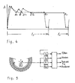
- FIG. 4 shows the filling level curve over time for two differently filtering products due to the influence of the batch-dependent suspension feed.
- the solid line shows the normal batch flow with the operations: Filling, filtering, adding washing liquid, spinning up to the immersion point ET 0 , dry spin, Clear out
- the dashed line shows the batch process for grain enlargement and increase in the feed concentration.
- the rate of rise is somewhat slower when filling because the product filters better.
- the filling valve is closed and the liquid level drops more steeply.
- the washing liquid can be added immediately; the water level drops faster.
- the immersion point ET1 the dry spin phase begins, which 1 can be much shorter than in the normal case because of the steep drop (ie / dt). If the desired residual moisture has been reached, clearing can already start at R1. The cycle can then be repeated.
- Figure 5 shows a schematic representation of the process control.
- the quantities h and h ET to be measured on the centrifuge as a function of time are entered into the computer. From the differential quotient dh / dt during the filtering off of the mother liquor at point W and the differential quotient dh / dt during the washing liquid outflow at point ET, the batch-dependent change in the drying time required to reach a certain residual moisture at point R is calculated in a process computer and specified as the cycle time.
- the mean value can also be determined from the linearized course of the decrease in height over time or the difference quotient ⁇ h / coursen t of the quantities.
- An analog computer or a digital computer can be used as the process computer.
Landscapes
- Centrifugal Separators (AREA)
Applications Claiming Priority (2)
| Application Number | Priority Date | Filing Date | Title |
|---|---|---|---|
| DE3940057A DE3940057A1 (de) | 1989-12-04 | 1989-12-04 | Verfahren und vorrichtung zum betrieb einer filterzentrifuge |
| DE3940057 | 1989-12-04 |
Publications (2)
| Publication Number | Publication Date |
|---|---|
| EP0431426A1 true EP0431426A1 (fr) | 1991-06-12 |
| EP0431426B1 EP0431426B1 (fr) | 1994-01-26 |
Family
ID=6394776
Family Applications (1)
| Application Number | Title | Priority Date | Filing Date |
|---|---|---|---|
| EP90122453A Expired - Lifetime EP0431426B1 (fr) | 1989-12-04 | 1990-11-26 | Procédé et installation pour opérer une centrifugeuse filtrante |
Country Status (5)
| Country | Link |
|---|---|
| US (1) | US5093010A (fr) |
| EP (1) | EP0431426B1 (fr) |
| JP (1) | JPH03270750A (fr) |
| DE (2) | DE3940057A1 (fr) |
| ES (1) | ES2048391T3 (fr) |
Cited By (2)
| Publication number | Priority date | Publication date | Assignee | Title |
|---|---|---|---|---|
| WO1993015843A1 (fr) * | 1992-02-18 | 1993-08-19 | Henkel Kommanditgesellschaft Auf Aktien | Procede pour utiliser en continu un separateur et accessoires pour ledit separateur |
| WO2015059091A1 (fr) * | 2013-10-21 | 2015-04-30 | Gea Mechanical Equipment Gmbh | Procédé de clarification d'un produit fluide au moyen d'une centrifugeuse |
Families Citing this family (2)
| Publication number | Priority date | Publication date | Assignee | Title |
|---|---|---|---|---|
| US5897786A (en) * | 1997-03-24 | 1999-04-27 | The Western States Machine Company | Method and apparatus for determining thickness of a charge wall being formed in a centrifugal machine |
| US6296774B1 (en) | 1999-01-29 | 2001-10-02 | The Western States Machine Company | Centrifuge load control for automatic infeed gate adjustment |
Citations (3)
| Publication number | Priority date | Publication date | Assignee | Title |
|---|---|---|---|---|
| DE3515915A1 (de) * | 1985-05-03 | 1986-11-06 | Braunschweigische Maschinenbauanstalt AG, 3300 Braunschweig | Ueberwachungsverfahren und vorrichtung zur kontrolle des sirupablaufes bei periodisch arbeitenden zuckerzentrifugen |
| DE3615013C1 (en) * | 1986-05-02 | 1987-06-11 | Krauss Maffei Ag | Method for monitoring the drying phase in filtration centrifuges |
| DE3822225C1 (fr) * | 1988-07-01 | 1989-07-20 | Laboratorium Prof. Dr. Rudolf Berthold, 7547 Wildbad, De |
Family Cites Families (13)
| Publication number | Priority date | Publication date | Assignee | Title |
|---|---|---|---|---|
| NL174555B (nl) * | 1951-12-12 | Mo Textilny I | Werkwijze voor de bereiding van gemodificeerde entcopolymeren van cellulose met monovinylmonomeren, alsmede geheel of gedeeltelijk daaruit vervaardigd textielmateriaal. | |
| US3117233A (en) * | 1961-06-21 | 1964-01-07 | American Plant Equipment Compa | Filter cake thickness detector for filtering apparatus |
| US3204766A (en) * | 1961-07-17 | 1965-09-07 | Industrial Filter Pump Mfg Co | Filter cake thickness detector |
| US3141846A (en) * | 1962-04-05 | 1964-07-21 | Western States Machine Co | Load control unit for cyclical centrifugal installation |
| DE1186411B (de) * | 1963-10-03 | 1965-01-28 | Krauss Maffei Ag | Schaelzentrifuge, insbesondere fuer langsam filtrierende Suspensionen |
| DE2441849A1 (de) * | 1974-08-31 | 1976-03-18 | Titus Hans Joachim | Vollautomatische fuellsteuerung fuer zentrifugen |
| US4014498A (en) * | 1975-01-15 | 1977-03-29 | Alfa-Laval Ab | Method and apparatus for centrifuging sludge-containing liquids |
| DE2525232A1 (de) * | 1975-06-06 | 1976-12-16 | Riedel De Haen Ag | Vorrichtung zur messung der fuellschichthoehe einer siebschleuder |
| CH604907A5 (fr) * | 1975-11-14 | 1978-09-15 | Sandoz Ag | |
| DD218283A1 (de) * | 1983-05-31 | 1985-02-06 | Kali Veb K | Vorrichtung zur steuerung mehrerer schaelschleudern |
| GB8517762D0 (en) * | 1985-07-15 | 1985-08-21 | British Nuclear Fuels Plc | Centrifuges |
| DE3632176A1 (de) * | 1986-09-22 | 1988-04-07 | Fresenius Ag | Steuerung eines systems zur trennung der bestandteile des einem spender "in vivo" entnommenen blutes |
| DE3726227A1 (de) * | 1987-08-07 | 1989-02-16 | Krauss Maffei Ag | Vorrichtung zum ergebnisabhaengigen steuern einer filterzentrifuge |
-
1989
- 1989-12-04 DE DE3940057A patent/DE3940057A1/de active Granted
-
1990
- 1990-11-26 DE DE90122453T patent/DE59004414D1/de not_active Expired - Fee Related
- 1990-11-26 EP EP90122453A patent/EP0431426B1/fr not_active Expired - Lifetime
- 1990-11-26 ES ES90122453T patent/ES2048391T3/es not_active Expired - Lifetime
- 1990-11-26 JP JP2318177A patent/JPH03270750A/ja active Pending
- 1990-12-03 US US07/621,744 patent/US5093010A/en not_active Expired - Fee Related
Patent Citations (3)
| Publication number | Priority date | Publication date | Assignee | Title |
|---|---|---|---|---|
| DE3515915A1 (de) * | 1985-05-03 | 1986-11-06 | Braunschweigische Maschinenbauanstalt AG, 3300 Braunschweig | Ueberwachungsverfahren und vorrichtung zur kontrolle des sirupablaufes bei periodisch arbeitenden zuckerzentrifugen |
| DE3615013C1 (en) * | 1986-05-02 | 1987-06-11 | Krauss Maffei Ag | Method for monitoring the drying phase in filtration centrifuges |
| DE3822225C1 (fr) * | 1988-07-01 | 1989-07-20 | Laboratorium Prof. Dr. Rudolf Berthold, 7547 Wildbad, De |
Cited By (5)
| Publication number | Priority date | Publication date | Assignee | Title |
|---|---|---|---|---|
| WO1993015843A1 (fr) * | 1992-02-18 | 1993-08-19 | Henkel Kommanditgesellschaft Auf Aktien | Procede pour utiliser en continu un separateur et accessoires pour ledit separateur |
| WO2015059091A1 (fr) * | 2013-10-21 | 2015-04-30 | Gea Mechanical Equipment Gmbh | Procédé de clarification d'un produit fluide au moyen d'une centrifugeuse |
| CN105658338A (zh) * | 2013-10-21 | 2016-06-08 | Gea机械设备有限公司 | 用于利用离心机、尤其是分离机澄清可流动的产品的方法 |
| US10040076B2 (en) | 2013-10-21 | 2018-08-07 | Gea Mechanical Equipment Gmbh | Method for clarifying a flowable product with a centrifuge having discontinuously openable solid-discharge openings |
| RU2672412C2 (ru) * | 2013-10-21 | 2018-11-14 | Геа Меканикал Эквипмент Гмбх | Способ осветления текучего продукта при помощи центрифуги |
Also Published As
| Publication number | Publication date |
|---|---|
| US5093010A (en) | 1992-03-03 |
| ES2048391T3 (es) | 1994-03-16 |
| EP0431426B1 (fr) | 1994-01-26 |
| JPH03270750A (ja) | 1991-12-02 |
| DE59004414D1 (de) | 1994-03-10 |
| DE3940057C2 (fr) | 1993-08-05 |
| DE3940057A1 (de) | 1991-06-06 |
Similar Documents
| Publication | Publication Date | Title |
|---|---|---|
| DE2015981C3 (de) | Verfahren zum Betrieb eines Druckfilters unter Verwendung eines Filterhilfsmittels und danach arbeitendes Filter | |
| DE3612825C2 (fr) | ||
| DE102016112112B4 (de) | Zentrifugalfiltervorrichtung | |
| DE69010038T2 (de) | Filteranlage für faserige Substanzen. | |
| EP3060350B1 (fr) | Procédé de clarification d'un produit fluide avec une centrifugeuse | |
| EP0359900B1 (fr) | Procédé de séparation de substances de haut poids moléculaire à partir de milieux nutritifs liquides ainsi qu'une installation pour la mise en oeuvre du procédé | |
| EP3085452B1 (fr) | Centrifugeuse discontinue doté d'un dispositif de commande destiné à commander le fonctionnement de la centrifugeuse et procédé de fonctionnement de la centrifugeuse | |
| EP0485901B1 (fr) | Procédé de pressurage et dispositif pour sa mise en oeuvre | |
| EP3600680B1 (fr) | Procédé servant à purger de manière automatisée des matières solides de centrifugeuses | |
| EP3060352B1 (fr) | Procédé de clarification d'un produit fluide au moyen d'une centrifugeuse | |
| DE2137428C3 (de) | Verfahren zum Regerieren von aus Körnern bestehenden Filtermaterial ein Filterbettes | |
| EP0431426B1 (fr) | Procédé et installation pour opérer une centrifugeuse filtrante | |
| EP2358479B1 (fr) | Ensemble hydrocyclone | |
| DE69005044T2 (de) | Verfahren zur automatischen Steuerung einer diskontinuierlich angetriebenen Zentrifuge. | |
| DE3523998A1 (de) | Verfahren und vorrichtung zur wiedererlangung von feststoffen aus einem strom | |
| EP4426458B1 (fr) | Procédé et filtre-presse pour la production de granulés à partir d'un liquide chargé de particules, et installation de production de granulés | |
| EP0443382B1 (fr) | Procédé de nettoyage de l'élément filtrant d'une centrifugeuse filtrante | |
| DE4104752C2 (fr) | ||
| DE3822225C1 (fr) | ||
| DE2745310A1 (de) | Verfahren und vorrichtung zur messung der durchlaessigkeit von filtermitteln | |
| DE69118573T2 (de) | Optimale zentrifugale Trennung | |
| CH615604A5 (fr) | ||
| DE3720961C1 (de) | Verfahren zum Abscheiden des Kaesestaubes aus Molke | |
| DE4004584A1 (de) | Verfahren und vorrichtung zum betrieb einer filterzentrifuge | |
| EP4008420B1 (fr) | Procédé et appareil de lavage d'un gâteau de filtration sur un moyen de filtration |
Legal Events
| Date | Code | Title | Description |
|---|---|---|---|
| PUAI | Public reference made under article 153(3) epc to a published international application that has entered the european phase |
Free format text: ORIGINAL CODE: 0009012 |
|
| AK | Designated contracting states |
Kind code of ref document: A1 Designated state(s): CH DE ES FR GB IT LI |
|
| 17P | Request for examination filed |
Effective date: 19910611 |
|
| 17Q | First examination report despatched |
Effective date: 19920807 |
|
| GRAA | (expected) grant |
Free format text: ORIGINAL CODE: 0009210 |
|
| AK | Designated contracting states |
Kind code of ref document: B1 Designated state(s): CH DE ES FR GB IT LI |
|
| GBT | Gb: translation of ep patent filed (gb section 77(6)(a)/1977) |
Effective date: 19940124 |
|
| ET | Fr: translation filed | ||
| REF | Corresponds to: |
Ref document number: 59004414 Country of ref document: DE Date of ref document: 19940310 |
|
| REG | Reference to a national code |
Ref country code: ES Ref legal event code: FG2A Ref document number: 2048391 Country of ref document: ES Kind code of ref document: T3 |
|
| ITF | It: translation for a ep patent filed | ||
| PG25 | Lapsed in a contracting state [announced via postgrant information from national office to epo] |
Ref country code: GB Effective date: 19941126 |
|
| PLBE | No opposition filed within time limit |
Free format text: ORIGINAL CODE: 0009261 |
|
| STAA | Information on the status of an ep patent application or granted ep patent |
Free format text: STATUS: NO OPPOSITION FILED WITHIN TIME LIMIT |
|
| PG25 | Lapsed in a contracting state [announced via postgrant information from national office to epo] |
Ref country code: ES Free format text: LAPSE BECAUSE OF NON-PAYMENT OF DUE FEES Effective date: 19941127 |
|
| PG25 | Lapsed in a contracting state [announced via postgrant information from national office to epo] |
Ref country code: LI Effective date: 19941130 Ref country code: CH Effective date: 19941130 |
|
| 26N | No opposition filed | ||
| GBPC | Gb: european patent ceased through non-payment of renewal fee |
Effective date: 19941126 |
|
| PG25 | Lapsed in a contracting state [announced via postgrant information from national office to epo] |
Ref country code: FR Effective date: 19950731 |
|
| REG | Reference to a national code |
Ref country code: CH Ref legal event code: PL |
|
| REG | Reference to a national code |
Ref country code: FR Ref legal event code: ST |
|
| REG | Reference to a national code |
Ref country code: ES Ref legal event code: FD2A Effective date: 19951214 |
|
| PG25 | Lapsed in a contracting state [announced via postgrant information from national office to epo] |
Ref country code: IT Free format text: LAPSE BECAUSE OF NON-PAYMENT OF DUE FEES;WARNING: LAPSES OF ITALIAN PATENTS WITH EFFECTIVE DATE BEFORE 2007 MAY HAVE OCCURRED AT ANY TIME BEFORE 2007. THE CORRECT EFFECTIVE DATE MAY BE DIFFERENT FROM THE ONE RECORDED. Effective date: 20051126 |
|
| PGFP | Annual fee paid to national office [announced via postgrant information from national office to epo] |
Ref country code: DE Payment date: 20060120 Year of fee payment: 16 |
|
| PG25 | Lapsed in a contracting state [announced via postgrant information from national office to epo] |
Ref country code: DE Free format text: LAPSE BECAUSE OF NON-PAYMENT OF DUE FEES Effective date: 20070601 |