EP0431449A2 - Système de surveillance pour aéronefs - Google Patents
Système de surveillance pour aéronefs Download PDFInfo
- Publication number
- EP0431449A2 EP0431449A2 EP90122695A EP90122695A EP0431449A2 EP 0431449 A2 EP0431449 A2 EP 0431449A2 EP 90122695 A EP90122695 A EP 90122695A EP 90122695 A EP90122695 A EP 90122695A EP 0431449 A2 EP0431449 A2 EP 0431449A2
- Authority
- EP
- European Patent Office
- Prior art keywords
- interrogation
- pulse
- interval
- time
- cycle
- Prior art date
- Legal status (The legal status is an assumption and is not a legal conclusion. Google has not performed a legal analysis and makes no representation as to the accuracy of the status listed.)
- Withdrawn
Links
Images



Classifications
-
- G—PHYSICS
- G01—MEASURING; TESTING
- G01S—RADIO DIRECTION-FINDING; RADIO NAVIGATION; DETERMINING DISTANCE OR VELOCITY BY USE OF RADIO WAVES; LOCATING OR PRESENCE-DETECTING BY USE OF THE REFLECTION OR RERADIATION OF RADIO WAVES; ANALOGOUS ARRANGEMENTS USING OTHER WAVES
- G01S13/00—Systems using the reflection or reradiation of radio waves, e.g. radar systems; Analogous systems using reflection or reradiation of waves whose nature or wavelength is irrelevant or unspecified
- G01S13/74—Systems using reradiation of radio waves, e.g. secondary radar systems; Analogous systems
- G01S13/76—Systems using reradiation of radio waves, e.g. secondary radar systems; Analogous systems wherein pulse-type signals are transmitted
- G01S13/78—Systems using reradiation of radio waves, e.g. secondary radar systems; Analogous systems wherein pulse-type signals are transmitted discriminating between different kinds of targets, e.g. IFF-radar, i.e. identification of friend or foe
- G01S13/781—Secondary Surveillance Radar [SSR] in general
-
- G—PHYSICS
- G01—MEASURING; TESTING
- G01S—RADIO DIRECTION-FINDING; RADIO NAVIGATION; DETERMINING DISTANCE OR VELOCITY BY USE OF RADIO WAVES; LOCATING OR PRESENCE-DETECTING BY USE OF THE REFLECTION OR RERADIATION OF RADIO WAVES; ANALOGOUS ARRANGEMENTS USING OTHER WAVES
- G01S13/00—Systems using the reflection or reradiation of radio waves, e.g. radar systems; Analogous systems using reflection or reradiation of waves whose nature or wavelength is irrelevant or unspecified
- G01S13/88—Radar or analogous systems specially adapted for specific applications
- G01S13/93—Radar or analogous systems specially adapted for specific applications for anti-collision purposes
- G01S13/933—Radar or analogous systems specially adapted for specific applications for anti-collision purposes of aircraft or spacecraft
Definitions
- the invention pertains to traffic alert collision avoidance systems and more particularly to such systems that cooperatively function with Air Traffic Control Radar Beacon Systems which provide intruder aircraft radar beacon surveillance.
- a Traffic Alert and Collision Avoidance System installed on an aircraft cooperates with Air Traffic Control (ATC) by utilizing ATC Radar Beacon Systems (ATCRBS) transponders installed in most aircraft world wide and the new Mode S Transponders to provide locations of other aircraft in the immediate vicinity of the TCAS equipped aircraft.
- TCAS provides surveillance within the ATC System by transmitting interrogating signals to the ATCRBS equipped aircraft and measuring the relative range, altitude, and bearing from the responses of the ATCRBS transponder. The measured data and the rate of change of this data are utilized by TCAS to provide a prediction of aircraft penetration into a predetermined TCAS protection volume within a subsequent flight time of approximately thirty seconds. When an aircraft penetration is predicted within this time, an advisory is given to the pilot to climb to a new altitude, maintain its present altitude, or descends from his present altitude.
- ATCRBS equipped aircraft respond to a non-unique interrogation.
- all ATCRBS transponders answer to the same interrogation when detected.
- Mode-S transponders respond to a unique address and may therefore be individually interrogated.
- To provide adequate surveillance of ATCRBS equipped aircraft a procedure has been developed that segments the air space in the manner that permits only a limited number ATCRBS equipped aircraft to respond at one time. This procedure, known as Whisper-Shout interrogates aircraft with increasingly stronger signals so that aircraft at short ranges from the interrogating aircraft reply before aircraft located at longer ranges.
- ATCRBS transponders reply after two interrogation pulses, spaced twenty-one microseconds apart have been detected. These transponders are designed to suppress a response when two pulses two microseconds apart are detected.
- a suppression pulse having an amplitude lower than the interrogation pulse amplitudes, is transmitted two microseconds before the first interrogation pulse, as explained in the aforementioned copending patent application.
- the suppression pulse and the first interrogation pulse will be detected at the shorter ranges and the responses from the ATCRBS equipped aircraft at these shorter ranges will be suppressed.
- Replies of all transponders are detected by the TCAS receiver, whether triggered by the TCAS interrogator associated with that receiver, other TCAS interrogators, or by ground station interrogators.
- Detected replies triggered by interrogators other than the one associated with the detecting receiver commonly referred to as "fruit", if synchronous with the interrogation transmissions of the interrogator associated with the receiver may cause the system to establish false target tracks. This may occur if, in three successive interrogation intervals, replies are received that match within one-third of a nautical mile (4.12 microseconds). Synchronous detections of responses triggered by interrogators other than that associated with the receiver may most likely occur in five known situations;
- an interrogator of a threat surveillance system provides first pseudo-random variable time intervals between interrogation cycles transmitted by an interrogator in a manner such that receiver range gates of an interrogation cycle do not overlap the receiver range gates of the preceding interrogation cycle.
- This range gate jittering significantly reduces synchronous fruit established by intruder aircraft transponder replies to interrogations from ground stations.
- a second pseudorandom variable delay between interrogation signal cycles provides a jitter to the time locations of the correlations windows within the range gate so that responses to interrogations from ground stations or other TCAS interrogations which, even with the range gate jittering, occur in more than one range gate,do not occur in corresponding correlation windows. Since replies must occur within a correlation window of a range gate for three successive interrogation cycles a second reduction of synchronous fruit replies is realized with this second pseudorandom intercycle delay.
- An ATCRBS transponder on an aircraft 11 receives interrogation signals from scanning antennas 12a and 13a located at ground stations 12 and 13, respectively. After the transmission of the interrogation signals side lobe suppression pulses are radiated from only directional antennas 12b and 13b associated with the scanning antennas 12a and 13a, respectively. In addition to these interrogation signals and suppression pulses, the transponder on the aircraft 11 receives interrogation signals from TCAS on an aircraft 14. Replies to these interrogation signals are transmitted on a very broad beam and are all therefore available for detection by a receiver associated with each interrogator.
- Interrogation signals from an aircraft 14 are arranged to enable the ground stations 12 and 13 to ignore responses from transponders on an aircraft 11 resulting from interrogations from the aircraft 14. In general, responses from the aircraft 11 to ground stations 12 and 13 interrogations are not synchronous with interrogation transmissions from the aircraft 14. Situations may exist, however, wherein transmissions from a ground station, or a multiplicity of ground stations, and responses to these interrogations may establish a sequence of signals at the receiver on the aircraft 14 which are in synchronism with the interrogation signals transmitted from that aircraft. How this may occur will be explained with reference to Figures 2,3,and 4.
- Each interrogation cycle includes eighty-three interrogation transmissions of increasing amplitude (whisper-shout), as explained in the aforementioned copending patent application, a spacing of three (3) msec between each interrogation, and a delay period from the completion of the last eighty-three interrogations before the commencement of a subsequent eighty-three interrogations of the next cycle.
- Each cycle period is nominally equal to one second which is jittered in integral multiples of one hundred milliseconds (N j ) to prevent the TCAS from interfering with ground station surveillance.
- the N j jitter does not significantly reduce the synchronous fruit established at the TCAS receiver.
- Reduction of the synchronous fruit at the TCAS receiver is accomplished by providing of two additional jitters N1R G and N2G, where N1 and N2 are pseudo random numbers, R G is the range gate time interval and G is the time width of a correlation window. These two additional jitters in the interrogation transmission cycle will be discussed subsequently.
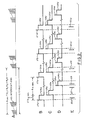
- the cycle C has been jittered to displace its range gates by one range gate interval from that of cycle B, while cycle D has been jittered to displace its range gates by two range gate intervals relative to the cycle B.
- E vertical lines represent signals received at the TCAS due to responses by threat aircraft to interrogations from other TCAS interrogators and from ground station interrogations.
- Signals 21a, 21b, and 21c are within range gates of the first cycle
- signal 23 is within a range gate of the second cycle
- signal 25 is within a range gate of the third cycle
- signal 27 is not within any range gate of the three cycles.
- TCAS establishes tracks when replies are received that correlate to within 4.125 microseconds (0.333 nautical miles) in each of three successive interrogation cycles. Consequently, for the situation shown at E in Figure 2 TCAS will not establish a track. In this situation only the signals 21a and 25 correlate, but this correlation exists only for cycles B and D, there is no signal correlation in cycle C.
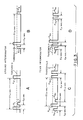
- An interrogation pulse sequence of a ground interrogator is shown at A in Figure 3.
- the sequence includes first P1 and second P3 interrogation pulses transmitted twenty-one microseconds apart from a ground station scanning antenna and a suppression pulse S transmitted on an omnidirectional antenna two microseconds after the transmission of the first interrogation pulse.
- a transponder will transmit a reply when two pulses twenty-one microseconds apart are detected, while responses will be suppressed when two pulses two microseconds apart are detected. Consequently, a response to an interrogation signal will be provided when P1 and P3 exceed a receiver threshold of the transponder while the suppression pulse S does not as shown at A in Figure 3.
- a response will be suppressed at the situation shown at B in Figure 3 exists. In this situation the suppression pulse exceeds the threshold.
- a TCAS interrogation signal sequence is shown at C in Figure 3. This sequence includes five pulses, first and second interrogation pulses P 1a and P 3a spaced twenty-one microseconds apart, a first suppression pulse S a , a second suppression pulse P 2a and a Mode-S suppression pulse P 4a .
- the purposes and transmission patterns for the signals S a , P 2a , and P 4a are fully described in the aforementioned copending application.
- D in Figure 3 is shown a signal situation at a transponder wherein the suppression pulse P 2a exceeds the transponder receiver threshold thereby suppressing replies.
- a full description of transponder operation in response to signal detections in the five pulse sequence is provided in the aforementioned copending application.
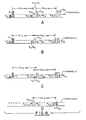
- FIG. 4 Four illustrations of signal detection situations which give rise to erroneous synchronous responses to a transponder interrogation is shown in Figure 4 at A, B, C, and D.
- A is shown a situation wherein a ground interrogator suppression pulse S and the first suppression pulse S a are detected by a transponder twenty-one microseconds apart.
- the receiver is disabled for 35 microseconds and the first interrogation pulse P 1a , which arrives two microseconds after the first suppression pulse S a , is not detected even though it exceeds the threshold.
- This situation provides a response that is twenty-three microseconds earlier than that which would have occurred by the detection of the two interrogation pulses P 1a and P 3a .
- a signal condition which triggers a false response from a transponder twenty-one microseconds before a true response is shown at B in Figure 4.
- a suppression pulse from a ground station interrogation sequence exceeds the transponder receiver threshold and the second ground station interrogation signal coincides with the first TCAS suppression signal with a phase relative to that of first TCAS suppression signal to establish a sum of the signals that does not exceed the transponder threshold.
- the detection of the ground station suppression signal S and the first TCAS interrogation signal P 1a twenty-one microseconds apart triggers the early response.
- a third signal situation which causes an erroneous response is shown at C in Figure 4.
- a second interrogation pulse P3, transmitted from the ground station coincides with the first interrogation pulse P 1a , the two signals adding with relative phasing to provide a resultant signal below the threshold, while the ground station's suppression signal S and the second interrogator suppression pulse P 2a exceed the threshold and are detected twenty-one microseconds apart.
- TCAS second suppression signal P 2a is transmitted nineteen microseconds before the second TCAS interrogation pulse P 3a , a response is triggered nineteen seconds before a true response would have been triggered if the first TCAS interrogation pulse P 1a and the second interrogation pulse P 3a , had been detected without the detection of any of the suppression pulses.
- a fourth erroneous response may be triggered by the signal situation shown at D in Figure 4.
- the second TCAS suppression pulse P 2a is detected and the ground station suppression pulse S coincides with the Mode-S suppression pulse P 4a , the two signals combining to provide a signal exceeding the threshold twenty-one microseconds from the detection of the second suppression pulse P 2a , all other signals being of an amplitude that do not exceed the TCAS transponder receiver threshold.
- the response to the signal detections arrives at the interrogator two microseconds after a response would have been received had the transponder detected the interrogation pulses P 1a and P 3a without detecting any of the suppression pulses.
- transponder replies in response to the signal situations at A, B, and C, which are established by the interference of multiple ground stations with a TCAS interrogation signals, established three synchronous replies within a 4.125 microsecond correlation window. These synchronous replies can cause the TCAS to establish a false track for a close - in fictitious target.
- an interrogation pulse sequence is the series of five (5) pulses transmitted by the transponder as the interrogation signal
- an interrogation scan is equal to 83 interrogation pulse sequence transmissions
- an interrogation cycle is an interrogation scan plus an interscan interval.
- TCAS interference with ground station operations is minimized by jittering the one second interinterrogation scan interval by pseudo-random integral multiples of one millisecond. This jittering does not significantly reduce the synchronous fruit at the TCAS receiver generated as described above. Reduction of this synchronous fruit may be accomplished by providing two additional jitters to the interscan interval. The first jitter provides range gates in an interrogation scan that do not overlap corresponding range gates in the previous scan, in this manner, any synchronous replies in a range gate of one interrogation scan will not be detected in a corresponding range gate of the other interrogation scan.
- the second additional jitter varies the interscan interval by pseudo-random multiples of a correlation widow, which may be 4.12 microseconds, used to form tracks of intruder aircraft.
- a correlation widow which may be 4.12 microseconds, used to form tracks of intruder aircraft.
- the two additional jitters minimize false tracks due to synchronous system noise inherent in the TCAS receivers and processors which may produce false non-altitude reporting replies and cause non-altitude reporting tracks without the additional two jitters.
- N j is the jitter for minimizing ground station interference by the TCAS which may vary between 0 and 100 msec
- N1 is a pseudo-random number
- R G is the length of a range gate which may be 173 microseconds to receive responses from aircraft within a 14 mile radius
- N2 is a second pseudo-random number
- G is the width of a correlation window which may be 4.12 microseconds.
- a pulse is applied to a fixed delay line wherein it may be delayed for 345 msec and applied to a variable delay line 35, which may be a countdown counter of the type well known in the art.
- the countdown for the variable delay 35 is set by a pseudo-random number generator 37 which may be triggered to provide a new pseudo-random number for the countdown by a pulse provided from the cycle transmitter 31 with the generation of the first pulse of an interrogation pulse sequence.
- the counter 35 is enabled by the pulse coupled from the fixed delay 33 and is clocked to count down from the pseudo-random number provided by the pseudo-random number generator (PRNG) 37 by a clock 39.
- PRNG pseudo-random number generator
- the PRNG 37 and the clock 39 are arranged to provide a psuedo-random delay that is between 0 and 200 milliseconds from the time the counter 35 is enabled by the pulse coupled from the fixed delay 33. Since the time required to transmit 83 interrogation pulse sequences is 0.555 seconds, delays provided by the combination of the fixed delay 33 and the variable delay 35 provides an interrogation cycle period that is between 0.9 and 1.1 seconds.
- Output pulses from the variable delay 35 are coupled to a second variable delay 41, which may be a countdown counter having the countdown number set by a PRNG 43 triggered to provide a new pseudo-random number by the pulse in the cycle generator 31 at the start of an interrogation sequence.
- Counter 41 is enabled by the pulse from the variable delay 35 and is clocked by pulses from the clock 39 to count down from the number set by the PRNG 43.
- the counter 41 provides a pulse at a time after the enabling pulse from the variable delay 35 that is equal to the number set from the counter 41 by the PRNG 43 times 173 microseconds, which is the width of a range gate for a 14 nautical mile surveillance.
- the output pulse from the variable delay 41 is coupled to enable a third variable delay 45 which has a countdown number set by a PRNG 47 and is clocked by pulses from clock 39.
- the pulses provided by the clock 39 and the number provided by the PRNG 47 cause counter 45 to provide a pulse at a time after the counter 45 has been enabled that is equal to an integral multiple of 4.12 microseconds which is the width of a correlation window.
- the pulse provided by the variable delay 45 is coupled to the cycle transmitter to initiate the next interrogation pulse sequence and is further coupled to reset the three countdown counters.
- a trigger pulse is coupled to the PRNGs 37, 43, and 47 to load new delay multiplying numbers into the countdown counters 35, 41, and 45.
- a trigger is provided by the cycle transmitter 31 to a range gate generator 49, which in turn provides a range gate to enable the receiver over the range gate time interval.
- the pseudo-random jittering of the interinterrogation pulse sequence may be provided through software applied to a computer.
- a flow chart for accomplishing this is shown in Figure 6 and a block diagram of such a system is shown in Figure 7. Though a specific order of random number calculations is shown in Figure 6, it should be recognized that this order may be varied without affecting the delay jittering.
- the cycle transmitter 31 provides a pulse to a computer 53 at the end of an interrogation scan ( 83 interrogation pulse sequences) and receives a start pulse for the next interrogation scan from the computer 53.
- the computer 53 calculates new pseudo-random numbers in pseudo-random number sub-routines 55, 57, and 59 which respectively correspond to the pseudo-random numbers N j , N1 , and N2.
- the pseudo-random numbers calculated in sub-routine 57 and the range gate interval stored in memory 61 are multiplied in sub-routine 63, while the pseudo-random number and the correlation window interval G are multiplied in sub-routine 65.
- the pseudo-random delays provided by a sub-routine 55 and a multiplying sub-routine 63 and 65 are added in a sub-routine 67 to a constant delay C and the result of the addition is stored in the memory 69.
- a pulse is provided by the computer to the cycle transmitter at a time after the reception at the end of scan pulse that is in accordance with the delay stored in the memory 69. At the same time the computer commences the calculation of the delay of the next interrogation scan.
- the range gate and correlation window jittering is applied to the interval between 83 interrogation pulse sequences, it should be recognized that variable delays may be applied between interrogation pulse sequences to accomplish the desired jittering.
- This type of jittering may be accomplished with the computerized systems shown in Figure 8.
- a pulse from a computer 70 triggers a sequence generator 71 which provides the interrogation pulse sequence to a transmitter 73 for transmission.
- the last pulse of the interrogation pulse sequence is coupled to the computer via a line 75 and initiates the calculation of the range gate and correlation window delay jittering to be applied to the three millisecond delay between interrogation pulse sequences. This is accomplished in a manner similar to that described with respect to Figure 7.
- Sub routines 77 and 79 calculate the pseudo-random number N1 and N2 which respectively multiply the range gate interval R G in the correlation window interval G stored in a memory 81 in multipliers 83 and 85.
- the results of the multiplications are added in sub-routine 87 to a constant delay C1 to provide a delay that is jittered about the nominal three millisecond interinterrogation pulse sequence interval and stored in memory 89.
- the computer provides a trigger pulse at a time after receiving the pulse on line 75 that is in accordance with the delay stored in memory 89.
- a counter 91 is incremented until 83 counts are achieved, whereafter a signal is provided to the computer 70 which inhibits the generation of a pulse for the initial interrogation sequence in the interrogation scan for the time interval stored in memory 93.
- the pulse from counter 91 also initiates the calculation of the inter-scan interval in sub-routine 95 which is thereafter stored in memory 3 for application at the next interscan interval.
Landscapes
- Engineering & Computer Science (AREA)
- Radar, Positioning & Navigation (AREA)
- Remote Sensing (AREA)
- Physics & Mathematics (AREA)
- Computer Networks & Wireless Communication (AREA)
- General Physics & Mathematics (AREA)
- Aviation & Aerospace Engineering (AREA)
- Electromagnetism (AREA)
- Radar Systems Or Details Thereof (AREA)
- Traffic Control Systems (AREA)
Applications Claiming Priority (2)
| Application Number | Priority Date | Filing Date | Title |
|---|---|---|---|
| US07/444,089 US5081457A (en) | 1989-11-30 | 1989-11-30 | Apparatus for reducing synchronous fruit in tcas surveillance systems |
| US444089 | 1989-11-30 |
Publications (2)
| Publication Number | Publication Date |
|---|---|
| EP0431449A2 true EP0431449A2 (fr) | 1991-06-12 |
| EP0431449A3 EP0431449A3 (en) | 1992-06-03 |
Family
ID=23763456
Family Applications (1)
| Application Number | Title | Priority Date | Filing Date |
|---|---|---|---|
| EP19900122695 Withdrawn EP0431449A3 (en) | 1989-11-30 | 1990-11-28 | Surveillance system for aircraft |
Country Status (3)
| Country | Link |
|---|---|
| US (1) | US5081457A (fr) |
| EP (1) | EP0431449A3 (fr) |
| JP (1) | JPH03231184A (fr) |
Cited By (2)
| Publication number | Priority date | Publication date | Assignee | Title |
|---|---|---|---|---|
| EP1512988A1 (fr) * | 2003-09-05 | 2005-03-09 | Kabushiki Kaisha Toshiba | Système de radar secondaire de surveillance, station terrestre pour l'usage à cet égard, et méthode pour vérifier le signal de réponse |
| US7554482B2 (en) * | 2004-09-15 | 2009-06-30 | Aviation Communication & Surveillance Systems | Systems and methods for using a TCAS directional antenna for omnidirectional transmission |
Families Citing this family (34)
| Publication number | Priority date | Publication date | Assignee | Title |
|---|---|---|---|---|
| FR2692996B1 (fr) * | 1992-06-30 | 1994-08-26 | Thomson Csf | Procédé et dispositif de filtrage des réponses dans un extracteur de radar secondaire. |
| US5218365A (en) * | 1992-07-02 | 1993-06-08 | Allied-Signal Inc. | Beacon interrogator beamwidth control using sidelobe signal integration in transponders |
| US5317316A (en) * | 1992-12-22 | 1994-05-31 | Honeywell Inc. | Method of altitude track initialization in an aircraft tracking system |
| US6240345B1 (en) * | 1993-04-15 | 2001-05-29 | Alliedsignal Inc. | Integrity monitor for TCAS mutual suppression |
| FR2707400B1 (fr) * | 1993-07-09 | 1995-08-18 | Thomson Csf | Procédé de placement dans le temps de transactions notamment entre un radar secondaire de modes et des avions. |
| FR2728369B1 (fr) * | 1994-12-19 | 1997-01-31 | Sgs Thomson Microelectronics | Procede et dispositif pour accroitre la securite d'un circuit integre |
| US5566074A (en) * | 1995-08-07 | 1996-10-15 | The Mitre Corporation | Horizontal miss distance filter system for suppressing false resolution alerts |
| US7667647B2 (en) * | 1999-03-05 | 2010-02-23 | Era Systems Corporation | Extension of aircraft tracking and positive identification from movement areas into non-movement areas |
| US7782256B2 (en) * | 1999-03-05 | 2010-08-24 | Era Systems Corporation | Enhanced passive coherent location techniques to track and identify UAVs, UCAVs, MAVs, and other objects |
| US7570214B2 (en) | 1999-03-05 | 2009-08-04 | Era Systems, Inc. | Method and apparatus for ADS-B validation, active and passive multilateration, and elliptical surviellance |
| US7889133B2 (en) * | 1999-03-05 | 2011-02-15 | Itt Manufacturing Enterprises, Inc. | Multilateration enhancements for noise and operations management |
| US7576695B2 (en) * | 1999-03-05 | 2009-08-18 | Era Systems Corporation | Multilateration enhancements for noise and operations management |
| US7908077B2 (en) * | 2003-06-10 | 2011-03-15 | Itt Manufacturing Enterprises, Inc. | Land use compatibility planning software |
| US7739167B2 (en) | 1999-03-05 | 2010-06-15 | Era Systems Corporation | Automated management of airport revenues |
| US8203486B1 (en) | 1999-03-05 | 2012-06-19 | Omnipol A.S. | Transmitter independent techniques to extend the performance of passive coherent location |
| US8446321B2 (en) | 1999-03-05 | 2013-05-21 | Omnipol A.S. | Deployable intelligence and tracking system for homeland security and search and rescue |
| US7777675B2 (en) | 1999-03-05 | 2010-08-17 | Era Systems Corporation | Deployable passive broadband aircraft tracking |
| US7612716B2 (en) * | 1999-03-05 | 2009-11-03 | Era Systems Corporation | Correlation of flight track data with other data sources |
| US20100079342A1 (en) * | 1999-03-05 | 2010-04-01 | Smith Alexander E | Multilateration enhancements for noise and operations management |
| ITRM20010176A1 (it) * | 2001-04-03 | 2002-10-03 | Univ Roma | Apparato ricevente ed elaborativo per segnali "replica" del radar secondario di sorveglianza con capacita' di super risoluzione. |
| US6617997B2 (en) | 2002-01-03 | 2003-09-09 | Aviation Communication & Surveillance Systems, Llc | Method of determining radio frequency link reliability in an aircraft tracking system |
| RU2215302C2 (ru) * | 2002-01-18 | 2003-10-27 | Государственное унитарное предприятие Государственный Рязанский приборный завод-дочернее предприятие государственного унитарного предприятия Военно-промышленного комплекса "МАПО" | Самолетный ответчик |
| US7965227B2 (en) * | 2006-05-08 | 2011-06-21 | Era Systems, Inc. | Aircraft tracking using low cost tagging as a discriminator |
| US8072310B1 (en) * | 2007-06-05 | 2011-12-06 | Pulsed Indigo Inc. | System for detecting and measuring parameters of passive transponders |
| JP5157697B2 (ja) * | 2008-07-10 | 2013-03-06 | 株式会社デンソー | 電子制御装置 |
| JP2010071745A (ja) * | 2008-09-17 | 2010-04-02 | Toshiba Corp | 二次監視レーダによるモードs質問の送信方法及び二次監視レーダ |
| JP5330211B2 (ja) * | 2009-12-07 | 2013-10-30 | 株式会社東芝 | 二次監視レーダ |
| US9647324B2 (en) * | 2013-12-04 | 2017-05-09 | Garmin International, Inc. | System and method for reducing reflections from metallic surfaces onto aircraft antennas |
| FR3075398B1 (fr) * | 2017-12-19 | 2020-01-10 | Thales | Procede de mesure de diagrammes d antenne d un radar secondaire et radar secondaire mettant en oeuvre un tel procede |
| US12276721B2 (en) | 2018-02-14 | 2025-04-15 | Seamatica Aerospace Ltd. | Method and apparatus for determining a position of an airborne vehicle using secondary surveillance radars as beacons |
| US12181565B2 (en) * | 2018-02-14 | 2024-12-31 | Seamatica Aerospace Ltd. | Aviation detect and avoid method and system |
| FR3085487B1 (fr) * | 2018-08-30 | 2020-07-31 | Thales Sa | Procede de caracterisation de la densite d'interrogations et de reponses mode s et radar secondaire mettant en oeuvre un tel procede |
| CN109683140A (zh) * | 2018-12-29 | 2019-04-26 | 陕西宝成航空仪表有限责任公司 | 一种空中交通监视设备实现旁瓣抑制的方法 |
| FR3103568B1 (fr) * | 2019-11-25 | 2021-12-03 | Thales Sa | Procede de detection de conflits de code ii/si d'identification de radar mode s avec des radars environnants, et radar secondaire mettant en oeuvre un tel procede |
Family Cites Families (11)
| Publication number | Priority date | Publication date | Assignee | Title |
|---|---|---|---|---|
| US4219817A (en) * | 1966-02-18 | 1980-08-26 | The United States Of America As Represented By The Secretary Of The Navy | Protection device for pulsed radar |
| US3705402A (en) * | 1970-05-27 | 1972-12-05 | Hughes Aircraft Co | Secondary radar defruiting system |
| GB1414164A (en) * | 1972-06-27 | 1975-11-19 | Rca Corp | Correlator and control system for vehicular collision avoidance |
| US4034371A (en) * | 1973-05-21 | 1977-07-05 | Siemens Aktiengesellschaft | Apparatus and methods for differentiating between synchronous and asynchronous response signals in secondary radar devices |
| US4008471A (en) * | 1975-04-14 | 1977-02-15 | Rca Corporation | Correlator to reduce bin straddle in a collision avoidance system |
| US4021802A (en) * | 1975-07-29 | 1977-05-03 | Litchstreet Co. | Collision avoidance system |
| GB1544774A (en) * | 1977-01-24 | 1979-04-25 | Secr Defence | Radio identification systems |
| FR2407487A1 (fr) * | 1977-10-26 | 1979-05-25 | Dassault Electronique | Procede pour faciliter l'exploitation a un aerodrome de messages radar de reponse recus a partir d'avions et installation pour la mise en oeuvre de ce procede |
| JPS61189032A (ja) * | 1985-02-15 | 1986-08-22 | Toyo Commun Equip Co Ltd | トランスポンダの応答信号等のパルス弁別方法 |
| JPS6352081A (ja) * | 1986-08-22 | 1988-03-05 | Mitsubishi Electric Corp | レ−ダ−におけるフル−ツ除去回路 |
| US4796030A (en) * | 1987-02-20 | 1989-01-03 | Eaton Corporation | Dual threshold amplitude detector |
-
1989
- 1989-11-30 US US07/444,089 patent/US5081457A/en not_active Expired - Lifetime
-
1990
- 1990-11-28 EP EP19900122695 patent/EP0431449A3/en not_active Withdrawn
- 1990-11-30 JP JP2337005A patent/JPH03231184A/ja active Pending
Cited By (3)
| Publication number | Priority date | Publication date | Assignee | Title |
|---|---|---|---|---|
| EP1512988A1 (fr) * | 2003-09-05 | 2005-03-09 | Kabushiki Kaisha Toshiba | Système de radar secondaire de surveillance, station terrestre pour l'usage à cet égard, et méthode pour vérifier le signal de réponse |
| US7095360B2 (en) | 2003-09-05 | 2006-08-22 | Kabushiki Kaisha Toshiba | Secondary surveillance radar system, ground equipment for use therein, and response signal checking method applied thereto |
| US7554482B2 (en) * | 2004-09-15 | 2009-06-30 | Aviation Communication & Surveillance Systems | Systems and methods for using a TCAS directional antenna for omnidirectional transmission |
Also Published As
| Publication number | Publication date |
|---|---|
| JPH03231184A (ja) | 1991-10-15 |
| EP0431449A3 (en) | 1992-06-03 |
| US5081457A (en) | 1992-01-14 |
Similar Documents
| Publication | Publication Date | Title |
|---|---|---|
| US5081457A (en) | Apparatus for reducing synchronous fruit in tcas surveillance systems | |
| US7095360B2 (en) | Secondary surveillance radar system, ground equipment for use therein, and response signal checking method applied thereto | |
| Obod et al. | Comparative analysis of noise immunity systems identification friend or foe | |
| US5528244A (en) | Processing for mode S signals suffering multipath distortion | |
| US5278563A (en) | Vehicle identification and classification systems | |
| US4910526A (en) | Airborne surveillance method and system | |
| US5075694A (en) | Airborne surveillance method and system | |
| CA2035811C (fr) | Radar a correlation polystatique | |
| US8279109B1 (en) | Aircraft bird strike avoidance method and apparatus using transponder | |
| US4107674A (en) | Collision avoidance system for aircrafts | |
| US4418349A (en) | Airport surveillance system | |
| EP2438463B1 (fr) | Système d'identification ami-ennemi (iff) | |
| CA1079838A (fr) | Systeme de prevention de collisions | |
| JP2991710B1 (ja) | Ssr装置及び航空機二次監視網 | |
| EP0184424B1 (fr) | Dispositif radar à impulsions composées avec élimination d'interférences entre les impulsions | |
| US4307400A (en) | Electronic countermeasures system and method of utilizing the same | |
| EP1123516B1 (fr) | Temps de tenue adaptatif pour poursuite radar | |
| US5463398A (en) | Method and apparatus for multiple reply rejection when decoding transponder replay signals | |
| US3715750A (en) | Omnidirectional reflected interrogation rejector | |
| US3718926A (en) | Instantaneous sidelobe interrogation decode suppressor | |
| US4975708A (en) | Time domain electronic antenna beam shaping | |
| JP3414316B2 (ja) | 航空機監視装置 | |
| SE8106798L (sv) | Navigationssystem | |
| US4067010A (en) | Circuit for inhibition of autogenetic false alarms in a collision avoidance system | |
| JP3042469B2 (ja) | 航空機監視システム |
Legal Events
| Date | Code | Title | Description |
|---|---|---|---|
| PUAI | Public reference made under article 153(3) epc to a published international application that has entered the european phase |
Free format text: ORIGINAL CODE: 0009012 |
|
| AK | Designated contracting states |
Kind code of ref document: A2 Designated state(s): DE FR GB IT |
|
| PUAL | Search report despatched |
Free format text: ORIGINAL CODE: 0009013 |
|
| AK | Designated contracting states |
Kind code of ref document: A3 Designated state(s): DE FR GB IT |
|
| 17P | Request for examination filed |
Effective date: 19921113 |
|
| 17Q | First examination report despatched |
Effective date: 19940722 |
|
| STAA | Information on the status of an ep patent application or granted ep patent |
Free format text: STATUS: THE APPLICATION HAS BEEN WITHDRAWN |
|
| 18W | Application withdrawn |
Withdrawal date: 19950107 |