EP0431486A1 - Panne de secteur dans une carderie - Google Patents
Panne de secteur dans une carderie Download PDFInfo
- Publication number
- EP0431486A1 EP0431486A1 EP90122916A EP90122916A EP0431486A1 EP 0431486 A1 EP0431486 A1 EP 0431486A1 EP 90122916 A EP90122916 A EP 90122916A EP 90122916 A EP90122916 A EP 90122916A EP 0431486 A1 EP0431486 A1 EP 0431486A1
- Authority
- EP
- European Patent Office
- Prior art keywords
- energy
- card
- drive
- power failure
- event
- Prior art date
- Legal status (The legal status is an assumption and is not a legal conclusion. Google has not performed a legal analysis and makes no representation as to the accuracy of the status listed.)
- Granted
Links
Images


Classifications
-
- D—TEXTILES; PAPER
- D01—NATURAL OR MAN-MADE THREADS OR FIBRES; SPINNING
- D01G—PRELIMINARY TREATMENT OF FIBRES, e.g. FOR SPINNING
- D01G15/00—Carding machines or accessories; Card clothing; Burr-crushing or removing arrangements associated with carding or other preliminary-treatment machines
- D01G15/02—Carding machines
- D01G15/12—Details
- D01G15/36—Driving or speed control arrangements
-
- H—ELECTRICITY
- H02—GENERATION; CONVERSION OR DISTRIBUTION OF ELECTRIC POWER
- H02J—ELECTRIC POWER NETWORKS; CIRCUIT ARRANGEMENTS OR SYSTEMS FOR SUPPLYING OR DISTRIBUTING ELECTRIC POWER; SYSTEMS FOR STORING ELECTRIC ENERGY
- H02J3/00—Circuit arrangements for AC mains or AC distribution networks
- H02J3/28—Arrangements for balancing of the load in networks by storage of energy
- H02J3/30—Arrangements for balancing of the load in networks by storage of energy using dynamo-electric machines coupled to flywheels
-
- H—ELECTRICITY
- H02—GENERATION; CONVERSION OR DISTRIBUTION OF ELECTRIC POWER
- H02J—ELECTRIC POWER NETWORKS; CIRCUIT ARRANGEMENTS OR SYSTEMS FOR SUPPLYING OR DISTRIBUTING ELECTRIC POWER; SYSTEMS FOR STORING ELECTRIC ENERGY
- H02J9/00—Circuit arrangements for emergency or stand-by power supply, e.g. for emergency lighting
- H02J9/04—Circuit arrangements for emergency or stand-by power supply, e.g. for emergency lighting in which the distribution system is disconnected from the normal source and connected to a standby source
- H02J9/06—Circuit arrangements for emergency or stand-by power supply, e.g. for emergency lighting in which the distribution system is disconnected from the normal source and connected to a standby source with automatic change-over, e.g. UPS systems
- H02J9/066—Circuit arrangements for emergency or stand-by power supply, e.g. for emergency lighting in which the distribution system is disconnected from the normal source and connected to a standby source with automatic change-over, e.g. UPS systems characterised by the use of dynamo-electric machines
-
- Y—GENERAL TAGGING OF NEW TECHNOLOGICAL DEVELOPMENTS; GENERAL TAGGING OF CROSS-SECTIONAL TECHNOLOGIES SPANNING OVER SEVERAL SECTIONS OF THE IPC; TECHNICAL SUBJECTS COVERED BY FORMER USPC CROSS-REFERENCE ART COLLECTIONS [XRACs] AND DIGESTS
- Y02—TECHNOLOGIES OR APPLICATIONS FOR MITIGATION OR ADAPTATION AGAINST CLIMATE CHANGE
- Y02E—REDUCTION OF GREENHOUSE GAS [GHG] EMISSIONS, RELATED TO ENERGY GENERATION, TRANSMISSION OR DISTRIBUTION
- Y02E60/00—Enabling technologies; Technologies with a potential or indirect contribution to GHG emissions mitigation
- Y02E60/16—Mechanical energy storage, e.g. flywheels or pressurised fluids
Definitions
- the invention lies in the field of textile technology and relates to a method and a device for bridging faults in the feed network during the operation of textile machines, in particular in a carding machine.
- Mains failures refer to voltage failures in the range of milliseconds or longer or voltage drops that are equivalent to a voltage failure, which differ from voltage fluctuations as discussed above.
- the converter network In the event of a power failure, the converter network usually fails, even if it is well regulated. It simply fails due to the lack of energy that is briefly omitted from the supply, which can affect the drive unit not only in the form of a "fluctuation", but also in the form of an abrupt interruption in function. Such a non-linear occurrence is beyond the control capability of a control network, as is generally used for such a type of drive system.
- the invention provides a card with means for energy recovery from the reel in the event of failure of supply from a main energy source (in the event of a power failure) and for forwarding this energy to the drive of at least one unit with an uncovered energy requirement.
- the energy recovered in the process can be used to maintain predetermined operating conditions between working elements of the card, if the substantial deviation from these conditions would cause a strip break.
- the greatly simplified circuit diagram according to FIG. 1 shows a frequency converter connected between network N and drive M.
- a three-phase three-phase current for example three times 380 volts with a frequency of 50 Hz, is usually converted from the power supply network into a (pulsating) direct current by a rectifier circuit G. This is used to supply a so-called direct current (or direct voltage) intermediate circuit K.
- a chopper circuit Z converts this DC voltage into a three-phase AC voltage which is used to supply an AC motor M.
- the speed of the motor is essentially proportional to the frequency applied. The speed of the motor M can thus be set by controlling the frequency of the current supplied by the chopper Z.
- Such a chopper circuit Z operates in both directions in terms of energy.
- the energy flows towards motor M.
- the line rectifier since the line rectifier only works in one direction in terms of energy, the energy emitted by the motor normally has to be destroyed by a so-called braking resistor in the intermediate circuit, or rather, converted into heat.
- This fact can now be used for energy management, with which the strictly specified speed ratio of a drive group, as occurs, for example, in a card with subsequent tape storage, can be maintained despite a power failure.
- Drive groups which are monitored by an energy management system according to the invention and are regulated accordingly in the event of a power failure, consist of individual drives in which at least one driven part has a significantly higher amount of kinetic energy at the time of the power failure than the other driven parts of the group.
- the card drum is the largest of the moving masses of a drive group, which, as already mentioned, includes the entire card and the tape storage.
- the swing energy of the rotating cardboard drum exceeds the energy of each individual drive or driven part.
- the driven parts there are more critical and less critical drives in terms of their contribution to the overall function.
- the feed roller via which the cardboard reel is fed, has relatively little swing energy, but its function is critical in relation to the speed of the customer. Reduces the feed roller Speed in relation to the speed of the customer rapidly, so the band fed to the card will tear.
- the required speed ratio between the customer and the feed roller can be continuously maintained with adequate control even with a decreasing reel speed. This means that the product quality may decrease, but there is no singular effect that can no longer be undone in the same process flow (without intervention).
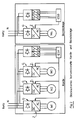
- Figure 2 shows the greatly simplified block diagrams of a card with tape storage.
- the main motor (for driving the reel and breeze) is indicated with M1, the motor for driving the feed roller with M2 and the motor for driving the customer with M3.
- the electronics control ESK is supplied with energy via a switching power supply SK.
- the tape storage device comprises a further motor M4 and a second switching power supply unit SB for feeding the control unit ESB of the tape storage device.
- the direct current (or direct voltage) intermediate circuits K for the individual motors are not shown in FIG. 2, they must be present between the respective rectifiers G and chopper Z according to the principle shown in FIG. 1.
- the main purpose of this arrangement of rectifiers, converters, drives and control electronics is to use the rotational energy (swing energy) stored in the rotating drum to bridge a shorter power failure.
- the intermediate circuit voltage is continuously measured by a monitoring unit E and supplied as a digital value to a microprocessor control ⁇ P (which is usually present anyway).
- ⁇ P microprocessor control
- this is programmed in such a way that it regulates the drive motors to the optimum speed for predetermined production quantities and carding action in order to produce a predetermined product (belt) quality.
- the intermediate circuit voltage drops below a threshold value which is preprogrammed for monitoring, which is reported to the processor control ⁇ P.
- the control immediately reduces the specified speed of the drum motor M1 in such a way that the motor M1 switches over to generator operation and begins to feed energy back into the common intermediate circuit.
- the production of the card can be maintained by using the energy released from the reel to feed the motors M2, M3 and M4.
- production can be reduced immediately by reducing the speed specifications of the M2, M3 and M4 motors.
- the customer motor M3 will then also switch from motor to generator operation and feed energy back into the common intermediate circuit.
- the control of the tape storage is therefore preferably connected to the card control in order to ensure the necessary coordination of the drives.
- the recuperation energy of the carding motors is not used to maintain the carding function, in particular the feed roller, during a power failure, as was only described, for example, but also for other critical components of the network.
- Critical are, for example, plant components that would cause an even greater production loss than a card failure in the event of a power failure, such as ring spinning machines, fans for transporting the fiber material and other process lines with sensitive processing procedures.
- FIG. 4 Such a system has been shown schematically in FIG. 4, where the cards are indicated by 100, the "critical consumers” by 102 and the “uncritical consumers” by 104. All consumers are connected to the network N via a central power distribution ZS.
- the power distribution ZS includes a power failure monitor NU, which disconnects the uncritical consumers 104 from the cards (and their energy recovery line RL) in the event of a power failure.
- the principle according to this invention can be implemented not only with frequency converter drives, but also with AC servos or DC controllers with an intermediate circuit which drive DG machines.
Landscapes
- Engineering & Computer Science (AREA)
- Power Engineering (AREA)
- Textile Engineering (AREA)
- Business, Economics & Management (AREA)
- Emergency Management (AREA)
- Preliminary Treatment Of Fibers (AREA)
Applications Claiming Priority (3)
| Application Number | Priority Date | Filing Date | Title |
|---|---|---|---|
| CH440389 | 1989-12-07 | ||
| CH440389 | 1989-12-07 | ||
| CH4403/89 | 1989-12-07 |
Publications (2)
| Publication Number | Publication Date |
|---|---|
| EP0431486A1 true EP0431486A1 (fr) | 1991-06-12 |
| EP0431486B1 EP0431486B1 (fr) | 2002-09-25 |
Family
ID=4275486
Family Applications (1)
| Application Number | Title | Priority Date | Filing Date |
|---|---|---|---|
| EP19900122916 Expired - Lifetime EP0431486B1 (fr) | 1989-12-07 | 1990-11-30 | Panne de secteur dans une carderie |
Country Status (4)
| Country | Link |
|---|---|
| EP (1) | EP0431486B1 (fr) |
| JP (1) | JPH03180518A (fr) |
| CA (1) | CA2031467A1 (fr) |
| DE (1) | DE59010930D1 (fr) |
Cited By (2)
| Publication number | Priority date | Publication date | Assignee | Title |
|---|---|---|---|---|
| FR2783367A1 (fr) * | 1998-09-14 | 2000-03-17 | Air Liquide | Systeme d'alimentation en energie electrique pour appareillage electrique |
| WO2003071671A1 (fr) * | 2002-02-22 | 2003-08-28 | Siemens Ag Österreich | Systeme de commande |
Citations (8)
| Publication number | Priority date | Publication date | Assignee | Title |
|---|---|---|---|---|
| BE675331A (fr) * | 1965-12-14 | 1966-05-16 | ||
| FR2252684A1 (fr) * | 1973-11-28 | 1975-06-20 | Siemens Ag | |
| CH581714A5 (fr) * | 1974-05-20 | 1976-11-15 | Rieter Ag Maschf | |
| US4172692A (en) * | 1978-04-18 | 1979-10-30 | Everett Wilhelm S | Pumping plant fly wheel hydraulic surge protector |
| US4339779A (en) * | 1980-08-27 | 1982-07-13 | A.C. Manufacturing Company | Apparatus for preventing damage by voltage interruption |
| DE3347113A1 (de) * | 1983-12-27 | 1985-07-18 | SKF GmbH, 8720 Schweinfurt | Spinn- oder zwirnmaschine mit einzelantrieb |
| DE3633627A1 (de) * | 1986-10-03 | 1988-04-14 | Schlafhorst & Co W | Verfahren und einrichtung zum betrieb einer textile faeden erzeugenden und/oder die faeden auf wickelkerne aufwickelnden maschine |
| DE3708211A1 (de) * | 1987-03-13 | 1988-09-22 | Truetzschler & Co | Vorrichtung zur verbesserung des kardierprozesses einer karde oder krempel |
-
1990
- 1990-11-30 EP EP19900122916 patent/EP0431486B1/fr not_active Expired - Lifetime
- 1990-11-30 JP JP33082790A patent/JPH03180518A/ja active Pending
- 1990-11-30 DE DE59010930T patent/DE59010930D1/de not_active Expired - Fee Related
- 1990-12-04 CA CA 2031467 patent/CA2031467A1/fr not_active Abandoned
Patent Citations (8)
| Publication number | Priority date | Publication date | Assignee | Title |
|---|---|---|---|---|
| BE675331A (fr) * | 1965-12-14 | 1966-05-16 | ||
| FR2252684A1 (fr) * | 1973-11-28 | 1975-06-20 | Siemens Ag | |
| CH581714A5 (fr) * | 1974-05-20 | 1976-11-15 | Rieter Ag Maschf | |
| US4172692A (en) * | 1978-04-18 | 1979-10-30 | Everett Wilhelm S | Pumping plant fly wheel hydraulic surge protector |
| US4339779A (en) * | 1980-08-27 | 1982-07-13 | A.C. Manufacturing Company | Apparatus for preventing damage by voltage interruption |
| DE3347113A1 (de) * | 1983-12-27 | 1985-07-18 | SKF GmbH, 8720 Schweinfurt | Spinn- oder zwirnmaschine mit einzelantrieb |
| DE3633627A1 (de) * | 1986-10-03 | 1988-04-14 | Schlafhorst & Co W | Verfahren und einrichtung zum betrieb einer textile faeden erzeugenden und/oder die faeden auf wickelkerne aufwickelnden maschine |
| DE3708211A1 (de) * | 1987-03-13 | 1988-09-22 | Truetzschler & Co | Vorrichtung zur verbesserung des kardierprozesses einer karde oder krempel |
Cited By (4)
| Publication number | Priority date | Publication date | Assignee | Title |
|---|---|---|---|---|
| FR2783367A1 (fr) * | 1998-09-14 | 2000-03-17 | Air Liquide | Systeme d'alimentation en energie electrique pour appareillage electrique |
| WO2000016461A1 (fr) * | 1998-09-14 | 2000-03-23 | L'air Liquide Societe Anonyme Pour L'etude Et L'exploitation Des Procedes Georges Claude | Systeme d'alimentation en energie electrique pour appareillage electrique |
| US6188143B1 (en) | 1998-09-14 | 2001-02-13 | L'air Liquide, Societe Anonyme Pour L'etude Et L'exploitation Des Procedes Georges Claude | System for supplying electrical energy to electrical apparatus |
| WO2003071671A1 (fr) * | 2002-02-22 | 2003-08-28 | Siemens Ag Österreich | Systeme de commande |
Also Published As
| Publication number | Publication date |
|---|---|
| DE59010930D1 (de) | 2002-10-31 |
| JPH03180518A (ja) | 1991-08-06 |
| CA2031467A1 (fr) | 1991-06-08 |
| EP0431486B1 (fr) | 2002-09-25 |
Similar Documents
| Publication | Publication Date | Title |
|---|---|---|
| EP0451534B1 (fr) | Machine textile, en particulier métier à filer à anneaux | |
| DE2521940C2 (de) | Schaltungsanordnung zum Steuern von Elektromotoren einer Spinnereimaschine | |
| DE102007021089B3 (de) | Verfahren zur Steuerung parallel geschalteter Ersatzstromquellen und Vorrichtung mit parallel geschalteten Ersatzstromquellen | |
| DE2116953B2 (de) | Antrieb einer offenendspinnmaschine | |
| EP3193012A1 (fr) | Agencement destinés à la surveillance d'une éolienne | |
| DE102010044901A1 (de) | Verfahren zum Betreiben einer Kreuzspulen herstellenden Textilmaschine und Kreuzspulen herstellende Textilmaschine | |
| DE6918595U (de) | Hilfsstromaggregat | |
| EP0389849A2 (fr) | Système de commande pour une machine textile | |
| CH667884A5 (de) | Einrichtung zum betreiben einer spinnerei- oder zwirnereimaschine. | |
| DE3347113A1 (de) | Spinn- oder zwirnmaschine mit einzelantrieb | |
| DE3633627C2 (de) | Verfahren und Einrichtung zum Betrieb einer textile Fäden erzeugenden und/oder die Fäden auf Wickelkerne aufwickelnden Maschine | |
| DE3029358A1 (de) | Einrichtung zur ueberbrueckung von kurzzeitigen netzausfaellen bei spannungszwischenkreis-umrichtern | |
| EP0408703B1 (fr) | Machine textile, notamment metier circulaire | |
| EP0440025B1 (fr) | Dispositif d'entraînement d'une machine à filer à bout libre | |
| DE3883685T2 (de) | Spinnmaschine. | |
| DE202020107140U1 (de) | Textilmaschine mit mehreren Arbeitsstellen und Versorgungseinheit | |
| EP0431486B1 (fr) | Panne de secteur dans une carderie | |
| DE4404243B4 (de) | Verfahren und Einrichtung zum Betreiben einer Offenend-Rotorspinneinheit mit einzelmotorischem elektrischem Antrieb des Spinnrotors | |
| DE19821251A1 (de) | Verfahren zum Betrieb einer Spinnmaschine | |
| EP0155472B1 (fr) | Procédé de commande d'entraînement de machines électriques | |
| EP0718422A1 (fr) | Machine de préparation d'enroulements de rubans de fibres | |
| EP2273000B1 (fr) | Poste de travail d'un métier à tisser à rotor à extrémité ouverte et procédé de fonctionnement du poste de travail | |
| CH691493A5 (de) | Antriebssystem für eine Spinnereimaschine, insbesondere Ringspinnmaschine. | |
| WO1985004908A1 (fr) | Metier a filer | |
| DE102007039915B4 (de) | Verfahren und Vorrichtung zum Stillsetzen einer Druckmaschine bei Netzausfall |
Legal Events
| Date | Code | Title | Description |
|---|---|---|---|
| PUAI | Public reference made under article 153(3) epc to a published international application that has entered the european phase |
Free format text: ORIGINAL CODE: 0009012 |
|
| 17P | Request for examination filed |
Effective date: 19910223 |
|
| AK | Designated contracting states |
Kind code of ref document: A1 Designated state(s): CH DE ES FR GB IT LI |
|
| 17Q | First examination report despatched |
Effective date: 19930810 |
|
| GRAG | Despatch of communication of intention to grant |
Free format text: ORIGINAL CODE: EPIDOS AGRA |
|
| GRAG | Despatch of communication of intention to grant |
Free format text: ORIGINAL CODE: EPIDOS AGRA |
|
| GRAH | Despatch of communication of intention to grant a patent |
Free format text: ORIGINAL CODE: EPIDOS IGRA |
|
| GRAH | Despatch of communication of intention to grant a patent |
Free format text: ORIGINAL CODE: EPIDOS IGRA |
|
| GRAA | (expected) grant |
Free format text: ORIGINAL CODE: 0009210 |
|
| AK | Designated contracting states |
Kind code of ref document: B1 Designated state(s): CH DE ES FR GB IT LI |
|
| PG25 | Lapsed in a contracting state [announced via postgrant information from national office to epo] |
Ref country code: GB Free format text: LAPSE BECAUSE OF FAILURE TO SUBMIT A TRANSLATION OF THE DESCRIPTION OR TO PAY THE FEE WITHIN THE PRESCRIBED TIME-LIMIT Effective date: 20020925 Ref country code: FR Free format text: LAPSE BECAUSE OF FAILURE TO SUBMIT A TRANSLATION OF THE DESCRIPTION OR TO PAY THE FEE WITHIN THE PRESCRIBED TIME-LIMIT Effective date: 20020925 |
|
| REG | Reference to a national code |
Ref country code: GB Ref legal event code: FG4D Free format text: NOT ENGLISH |
|
| REG | Reference to a national code |
Ref country code: CH Ref legal event code: EP |
|
| PGFP | Annual fee paid to national office [announced via postgrant information from national office to epo] |
Ref country code: DE Payment date: 20021024 Year of fee payment: 13 |
|
| REF | Corresponds to: |
Ref document number: 59010930 Country of ref document: DE Date of ref document: 20021031 |
|
| PG25 | Lapsed in a contracting state [announced via postgrant information from national office to epo] |
Ref country code: LI Free format text: LAPSE BECAUSE OF NON-PAYMENT OF DUE FEES Effective date: 20021130 Ref country code: CH Free format text: LAPSE BECAUSE OF NON-PAYMENT OF DUE FEES Effective date: 20021130 |
|
| GBV | Gb: ep patent (uk) treated as always having been void in accordance with gb section 77(7)/1977 [no translation filed] |
Effective date: 20020925 |
|
| PG25 | Lapsed in a contracting state [announced via postgrant information from national office to epo] |
Ref country code: ES Free format text: LAPSE BECAUSE OF FAILURE TO SUBMIT A TRANSLATION OF THE DESCRIPTION OR TO PAY THE FEE WITHIN THE PRESCRIBED TIME-LIMIT Effective date: 20030328 |
|
| REG | Reference to a national code |
Ref country code: CH Ref legal event code: PL |
|
| EN | Fr: translation not filed | ||
| PLBE | No opposition filed within time limit |
Free format text: ORIGINAL CODE: 0009261 |
|
| STAA | Information on the status of an ep patent application or granted ep patent |
Free format text: STATUS: NO OPPOSITION FILED WITHIN TIME LIMIT |
|
| 26N | No opposition filed |
Effective date: 20030626 |
|
| PG25 | Lapsed in a contracting state [announced via postgrant information from national office to epo] |
Ref country code: DE Free format text: LAPSE BECAUSE OF NON-PAYMENT OF DUE FEES Effective date: 20040602 |
|
| PG25 | Lapsed in a contracting state [announced via postgrant information from national office to epo] |
Ref country code: IT Free format text: LAPSE BECAUSE OF NON-PAYMENT OF DUE FEES;WARNING: LAPSES OF ITALIAN PATENTS WITH EFFECTIVE DATE BEFORE 2007 MAY HAVE OCCURRED AT ANY TIME BEFORE 2007. THE CORRECT EFFECTIVE DATE MAY BE DIFFERENT FROM THE ONE RECORDED. Effective date: 20051130 |