EP0431604A2 - Appareil de polarisation magnÀ©tique pour un appareil d'entraînement de disque magnéto-optique - Google Patents
Appareil de polarisation magnÀ©tique pour un appareil d'entraînement de disque magnéto-optique Download PDFInfo
- Publication number
- EP0431604A2 EP0431604A2 EP90123348A EP90123348A EP0431604A2 EP 0431604 A2 EP0431604 A2 EP 0431604A2 EP 90123348 A EP90123348 A EP 90123348A EP 90123348 A EP90123348 A EP 90123348A EP 0431604 A2 EP0431604 A2 EP 0431604A2
- Authority
- EP
- European Patent Office
- Prior art keywords
- permanent magnet
- coil
- magnetic field
- magnetic
- rotating
- Prior art date
- Legal status (The legal status is an assumption and is not a legal conclusion. Google has not performed a legal analysis and makes no representation as to the accuracy of the status listed.)
- Granted
Links
Images



Classifications
-
- G—PHYSICS
- G11—INFORMATION STORAGE
- G11B—INFORMATION STORAGE BASED ON RELATIVE MOVEMENT BETWEEN RECORD CARRIER AND TRANSDUCER
- G11B11/00—Recording on or reproducing from the same record carrier wherein for these two operations the methods are covered by different main groups of groups G11B3/00 - G11B7/00 or by different subgroups of group G11B9/00; Record carriers therefor
- G11B11/10—Recording on or reproducing from the same record carrier wherein for these two operations the methods are covered by different main groups of groups G11B3/00 - G11B7/00 or by different subgroups of group G11B9/00; Record carriers therefor using recording by magnetic means or other means for magnetisation or demagnetisation of a record carrier, e.g. light induced spin magnetisation; Demagnetisation by thermal or stress means in the presence or not of an orienting magnetic field
- G11B11/105—Recording on or reproducing from the same record carrier wherein for these two operations the methods are covered by different main groups of groups G11B3/00 - G11B7/00 or by different subgroups of group G11B9/00; Record carriers therefor using recording by magnetic means or other means for magnetisation or demagnetisation of a record carrier, e.g. light induced spin magnetisation; Demagnetisation by thermal or stress means in the presence or not of an orienting magnetic field using a beam of light or a magnetic field for recording by change of magnetisation and a beam of light for reproducing, i.e. magneto-optical, e.g. light-induced thermomagnetic recording, spin magnetisation recording, Kerr or Faraday effect reproducing
- G11B11/1055—Disposition or mounting of transducers relative to record carriers
- G11B11/10556—Disposition or mounting of transducers relative to record carriers with provision for moving or switching or masking the transducers in or out of their operative position
- G11B11/1056—Switching or mechanically reversing the magnetic field generator
Definitions
- This invention relates to a magnetic bias apparatus for a magnetooptical disk drive apparatus in which information is recorded on and erased from a recording medium using the magnetooptical effect.
- a magnetooptical recording apparatus using this technique is provided with a magnetic bias apparatus which is disposed in a position opposite to an optical head.
- Figure 11 diagrammatically illustrates a prior art magnetooptical recording apparatus.
- the apparatus of Figure 11 comprises a motor 1 a for rotating a magnetooptical disk 1, an optical head 2, and a magnetic bias apparatus A which faces the optical head 2 through the disk 1.
- the optical head 2 includes an object lens 2a, and a semiconductor laser device (not shown).
- the magnetic bias apparatus A has a permanent magnet 3, and a coil 4 which is arranged above the magnet 3 (i.e., above the N-pole of the magnet).
- the magnet 3 is rotatable about an axis 3a. When data erasing is performed.
- the S-pole of the magnet 3 is directed as shown in Figure 11 to face the disk 1 so as to produce a magnetic field of a predetermined direction, and a light beam emitted from the optical head 2 is converged onto the disk 1, thereby erasing data stored on the disk 1.
- the coil 4 is driven to rotate the magnet 3 about the axis 3a by a half turn, so that the N-pole faces the disk 1 and a magnetic field of a direction opposite to the predetermined direction is applied to the disk 1.
- a light beam modulated in accordance with the data to be recorded is converged onto the disk 1 to record the data on the disk.
- the relationships of the directions of the magnetic fields may be inverted, in other words, the magnet 3 may be positioned so that when data is to be erased the N-pole faces the disk 1 and when data is to be recorded the S-pole faces the disk 1.
- a magnetooptical recording apparatus should be as small and as thin as possible. For this reason, it is necessary for a magnetic bias apparatus also to be made as thin as possible.
- the coil 4 for reversing the direction of the magnetic field is positioned above the permanent magnet 3, and therefore the magnetic bias apparatus cannot be thinly constructed.
- Figure 12 illustrates another magnetic bias apparatus.
- the coil 4 and the permanent magnet 3 are juxtaposed in parallel so that the overall height of the apparatus can be decreased.
- the apparatus shown in Figure 12 can solve the above-mentioned problem, it has another problem in that the coil 4 generates the magnetic flux as shown in Figure 12, and therefore the rotating force f which is caused by the magnetic field of the coil 4 and acts on the magnet 3 is extremely small, resulting in that a significant amount of time is required for rotating the magnet 3 or the response characteristic of the magnetic bias apparatus is poor.
- the magnetic bias apparatus for a magnetooptical disk drive apparatus of this invention which overcomes the above-discussed and numerous other disadvantages and deficiencies of the prior art, comprises: a permanent magnet for generating a bias magnetic field, said permanent magnet being rotatable about a rotating axis; a coil for rotating said permanent magnet; and drive means for driving said coil, the central axis of said coil is directed toward said rotating axis and perpendicular to the line connecting both the two poles of said permanent magnet.
- a body of a ferromagnetic material is disposed at the center of said coil.
- the length of said body is smaller than the length of said coil along said central axis.
- said body is a substantially rectangular body.
- one of the surfaces of said body faces said permanent magnet.
- said one surface is a curved one which is concaved in the direction along said central axis and departing from said rotating axis of said permanent magnet.
- FIG. 1 shows an embodiment of this invention.
- the magnetic bias apparatus A of this embodiment comprises a permanent magnet 3 for generating a magnetic field, a coil 4 for rotating the permanent magnet 3.
- the permanent magnet 3 is rotatable about an axis 7 which is supported by an adequate supporting means (not shown).
- the apparatus A further comprises a driving circuit 8 for driving the coil 4, a magnetic detector 5 which detects the direction and strength of the magnetic field, and a changeover switch 9 by which the polarity of the voltage applied to the coil 4 is inverted in accordance with the output of the magnetic detector 5.
- the magnetic detector 5 detects the position or rotating angle of the permanent magnet 3, and in accordance with the degree of the detected rotating angle outputs a signal to the driving circuit 8, so that the amount and direction of the current flowing the coil 4 are controlled, thereby controlling the position or rotating angle of the permanent magnet 3. More specifically, the magnetic detector 5 outputs a voltage which corresponds to the strength of the magnetic field generated by the permanent magnet 3, and the output voltage is coupled to the driving circuit 8.
- the driving circuit 8 supplies a voltage for driving the coil 4 to rotate the permanent magnet 3 so that the poles of the magnet 3 are positioned at a desired positional relationship.
- the coil 4 is a cylindrical coil.
- the axis Y of the coil 4 is directed toward the axis 7 of the permanent magnet 3, and is perpendicular to the line (Z in Figure 5) connecting the N- and S-poles of the permanent magnet 3 when the magnet 3 is at either of the recording position or the erasing position.
- the switch 9 When the permanent magnet 3 is to be inverted or rotated, the switch 9 is set to the position for supplying a current of the direction by which a magnetic field of the direction as indicated by an arrow M in Figure 2 is generated, and the coil 4 is driven by the current.
- the direction of the force F caused by the magnetic field M of the coil 4 and applied to the magnet 3 coincides with the rotating direction of the magnet 3 at the initial stage of the rotation, whereby the force F is effectively applied to the magnet 3. According to this embodiment, therefore, the rapid inversion of the permanent magnet 3 can be achieved, and an efficient magnetic bias apparatus is obtained.
- FIG 3 diagrammatically illustrates another embodiment of the invention.
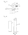
- This embodiment is constructed in the same manner as that shown in Figure 1 except that a body 10 having a rectangular section and made of a ferromagnetic material such as iron is fixedly positioned at the vicinity of the center of the coil 4.
- Figure 4 shows the positional relationship between the coil 4 and the ferromagnetic body 10.
- the magnetic field M Figure 2
- the ferromagnetic body 10 is magnetized by the magnetic field M.
- the existence of the magnetized ferromagnetic body 10 contributes to the further increase of the strength of the force F.
- Figure 6 illustrates the relationship between the length Lio of the ferromagnetic body 10 and the strength of the magnetic field produced by the coil 4.
- Figure 7 illustrates the change of the strength of the magnetic field produced by the permanent magnet 3 with the increase of the distance from the magnet.
- Figure 8 illustrates the relationship between the length L 10 of the ferromagnetic body 10 and the strength of the force F.
- the length L10 of the ferromagnetic body 10 is set to be from about 1/5 to about 4/5 of the length L 4 of the coil 4.
- Figure 9 shows a ferromagnetic body 11 used in another embodiment of the invention.
- the ferromagnetic body 11 is fixedly positioned at the vicinity of the center of the coil 4, in the same manner as the embodiment of Figure 3.
- the surface 11 a of the ferromagnetic body 11 which faces the permanent magnet 3 is curved or concaved in the direction opposite to the permanent magnet 3.
- the length L11 is gradually decreased, and has the minimum value at the center in the direction X ( Figure 5).
- the magnetic bias apparatus according to the invention is able to achieve high speed reversing of the magnetic field with a simple construction, and is suitable for a small and thin magnetooptical disk drive apparatus.
- the magnetic flux is used efficiently in the magnetic bias apparatus according to the invention, the amount of the current supplied to the coil can be reduced, with the result of the reduced electric power consumption.
- the present apparatus is very useful also in the view point of the electric power saving.
Applications Claiming Priority (4)
| Application Number | Priority Date | Filing Date | Title |
|---|---|---|---|
| JP316846/89 | 1989-12-06 | ||
| JP31684689A JP3211085B2 (ja) | 1989-12-06 | 1989-12-06 | 磁気バイアス装置 |
| JP240814/90 | 1990-09-10 | ||
| JP24081490A JP2867665B2 (ja) | 1990-09-10 | 1990-09-10 | 磁気バイアス装置 |
Publications (3)
| Publication Number | Publication Date |
|---|---|
| EP0431604A2 true EP0431604A2 (fr) | 1991-06-12 |
| EP0431604A3 EP0431604A3 (en) | 1992-09-02 |
| EP0431604B1 EP0431604B1 (fr) | 1995-03-29 |
Family
ID=26534940
Family Applications (1)
| Application Number | Title | Priority Date | Filing Date |
|---|---|---|---|
| EP90123348A Expired - Lifetime EP0431604B1 (fr) | 1989-12-06 | 1990-12-05 | Appareil de polarisation magnétique pour un appareil d'entraînement de disque magnéto-optique |
Country Status (3)
| Country | Link |
|---|---|
| US (1) | US5317548A (fr) |
| EP (1) | EP0431604B1 (fr) |
| DE (1) | DE69018207T2 (fr) |
Cited By (1)
| Publication number | Priority date | Publication date | Assignee | Title |
|---|---|---|---|---|
| EP1555738A1 (fr) * | 2004-01-15 | 2005-07-20 | Pektron Group Limited | Contrôle de moteur |
Families Citing this family (3)
| Publication number | Priority date | Publication date | Assignee | Title |
|---|---|---|---|---|
| US5345431A (en) * | 1992-09-14 | 1994-09-06 | Hewlett-Packard Company | Write and erase assembly for magneto-optic drive apparatus |
| JP3361598B2 (ja) * | 1994-01-31 | 2003-01-07 | 富士通株式会社 | 記憶装置のバイアス磁界印加方法 |
| US5544132A (en) * | 1995-03-13 | 1996-08-06 | Eastman Kodak Company | Apparatus for selectively inverting a magnetic biased field for magneto-optic recording |
Family Cites Families (6)
| Publication number | Priority date | Publication date | Assignee | Title |
|---|---|---|---|---|
| JPS60175201A (ja) * | 1984-02-20 | 1985-09-09 | Olympus Optical Co Ltd | バイアス磁界印加方式 |
| DE3650686T2 (de) * | 1985-04-29 | 1998-10-22 | Sony Corp | Externes Magnetfeld-Umpolungsgerät für magneto-optisches Plattengerät |
| US4701895A (en) * | 1986-03-28 | 1987-10-20 | Rca Corporation | Magnetic biasing apparatus for magneto-optic recording including a permanent magnet |
| JPH0727606B2 (ja) * | 1986-12-11 | 1995-03-29 | ソニー株式会社 | 記録型光デイスクに対する磁界印加装置 |
| US4962492A (en) * | 1988-04-29 | 1990-10-09 | Laser Magnetic Storage International Company | Magneto-optic data recording system, actuating device therefor and method of providing same |
| JPH0633526Y2 (ja) * | 1988-11-10 | 1994-08-31 | ティアツク株式会社 | 光磁気ディスク装置 |
-
1990
- 1990-12-05 EP EP90123348A patent/EP0431604B1/fr not_active Expired - Lifetime
- 1990-12-05 DE DE69018207T patent/DE69018207T2/de not_active Expired - Fee Related
-
1993
- 1993-07-29 US US08/099,763 patent/US5317548A/en not_active Expired - Fee Related
Cited By (1)
| Publication number | Priority date | Publication date | Assignee | Title |
|---|---|---|---|---|
| EP1555738A1 (fr) * | 2004-01-15 | 2005-07-20 | Pektron Group Limited | Contrôle de moteur |
Also Published As
| Publication number | Publication date |
|---|---|
| US5317548A (en) | 1994-05-31 |
| DE69018207T2 (de) | 1995-07-27 |
| DE69018207D1 (de) | 1995-05-04 |
| EP0431604A3 (en) | 1992-09-02 |
| EP0431604B1 (fr) | 1995-03-29 |
Similar Documents
| Publication | Publication Date | Title |
|---|---|---|
| US4959820A (en) | Magnetooptical recording apparatus with constant leakage magnetic and pulse modulated magnetic field | |
| EP0485359B1 (fr) | Appareil d'inversion du champ magnétique externe pour appareil à disque magnéto-optique | |
| KR960000829B1 (ko) | 자기 광 기록에 사용되는 코일용 회전 제어 장치 | |
| JPS62185269A (ja) | 光磁気記録装置 | |
| EP0431604B1 (fr) | Appareil de polarisation magnétique pour un appareil d'entraînement de disque magnéto-optique | |
| US5243580A (en) | Head for a magneto-optical recording apparatus | |
| US5351221A (en) | Apparatus for applying bias magnetic field including a rotatable magnet and a plurality of coils for controlling the rotation of the magnet | |
| KR100269496B1 (ko) | 자기 회로로부터의 누설 자계를 외부 바이어스 자계로서 이용하는 광디스크 드라이브 | |
| EP0241222A1 (fr) | Appareil d'enregistrement opto-magnétique pour moyens d'entraînements séquentiels destinés à des têtes optiques et moyens générateurs de champ magnétiques polarisés | |
| CA2033275C (fr) | Generateur de champ magnetique de polarisation | |
| JPS6334757A (ja) | 光磁気デイスク装置 | |
| JP2819613B2 (ja) | 光磁気ディスクドライブ装置 | |
| JP2867665B2 (ja) | 磁気バイアス装置 | |
| JP2881983B2 (ja) | 光磁気ピックアップ装置 | |
| JPH01184637A (ja) | 光学式ピックアップの補正駆動装置 | |
| JP3211085B2 (ja) | 磁気バイアス装置 | |
| JPS63317903A (ja) | バイアス磁界印加装置 | |
| JPH05114104A (ja) | バイアス磁界制御装置 | |
| JPS6258441A (ja) | 光磁気記録再生装置 | |
| JPH03154203A (ja) | 外部磁界印加装置 | |
| JPH06105483B2 (ja) | 光磁気記録のバイアス磁界印加装置 | |
| JPS634401A (ja) | 磁気バイアス発生装置 | |
| JPH0319102A (ja) | 光磁気記録用バイアス磁界発生装置 | |
| JPH05290423A (ja) | 光磁気ディスク装置 | |
| JPH06338003A (ja) | 磁界印加装置 |
Legal Events
| Date | Code | Title | Description |
|---|---|---|---|
| PUAI | Public reference made under article 153(3) epc to a published international application that has entered the european phase |
Free format text: ORIGINAL CODE: 0009012 |
|
| 17P | Request for examination filed |
Effective date: 19910115 |
|
| AK | Designated contracting states |
Kind code of ref document: A2 Designated state(s): DE FR GB IT |
|
| PUAL | Search report despatched |
Free format text: ORIGINAL CODE: 0009013 |
|
| AK | Designated contracting states |
Kind code of ref document: A3 Designated state(s): DE FR GB IT |
|
| 17Q | First examination report despatched |
Effective date: 19940801 |
|
| GRAA | (expected) grant |
Free format text: ORIGINAL CODE: 0009210 |
|
| AK | Designated contracting states |
Kind code of ref document: B1 Designated state(s): DE FR GB IT |
|
| ITF | It: translation for a ep patent filed | ||
| ET | Fr: translation filed | ||
| REF | Corresponds to: |
Ref document number: 69018207 Country of ref document: DE Date of ref document: 19950504 |
|
| PLBE | No opposition filed within time limit |
Free format text: ORIGINAL CODE: 0009261 |
|
| STAA | Information on the status of an ep patent application or granted ep patent |
Free format text: STATUS: NO OPPOSITION FILED WITHIN TIME LIMIT |
|
| 26N | No opposition filed | ||
| PGFP | Annual fee paid to national office [announced via postgrant information from national office to epo] |
Ref country code: GB Payment date: 20011205 Year of fee payment: 12 |
|
| PGFP | Annual fee paid to national office [announced via postgrant information from national office to epo] |
Ref country code: FR Payment date: 20011212 Year of fee payment: 12 |
|
| PGFP | Annual fee paid to national office [announced via postgrant information from national office to epo] |
Ref country code: DE Payment date: 20011217 Year of fee payment: 12 |
|
| REG | Reference to a national code |
Ref country code: GB Ref legal event code: IF02 |
|
| PG25 | Lapsed in a contracting state [announced via postgrant information from national office to epo] |
Ref country code: GB Free format text: LAPSE BECAUSE OF NON-PAYMENT OF DUE FEES Effective date: 20021205 |
|
| PG25 | Lapsed in a contracting state [announced via postgrant information from national office to epo] |
Ref country code: DE Free format text: LAPSE BECAUSE OF NON-PAYMENT OF DUE FEES Effective date: 20030701 |
|
| GBPC | Gb: european patent ceased through non-payment of renewal fee | ||
| PG25 | Lapsed in a contracting state [announced via postgrant information from national office to epo] |
Ref country code: FR Free format text: LAPSE BECAUSE OF NON-PAYMENT OF DUE FEES Effective date: 20030901 |
|
| REG | Reference to a national code |
Ref country code: FR Ref legal event code: ST |
|
| PG25 | Lapsed in a contracting state [announced via postgrant information from national office to epo] |
Ref country code: IT Free format text: LAPSE BECAUSE OF NON-PAYMENT OF DUE FEES;WARNING: LAPSES OF ITALIAN PATENTS WITH EFFECTIVE DATE BEFORE 2007 MAY HAVE OCCURRED AT ANY TIME BEFORE 2007. THE CORRECT EFFECTIVE DATE MAY BE DIFFERENT FROM THE ONE RECORDED. Effective date: 20051205 |