EP0431775A2 - Verfahren zur kontinuerlichen Endbearbeitung von Rohren - Google Patents
Verfahren zur kontinuerlichen Endbearbeitung von Rohren Download PDFInfo
- Publication number
- EP0431775A2 EP0431775A2 EP90312467A EP90312467A EP0431775A2 EP 0431775 A2 EP0431775 A2 EP 0431775A2 EP 90312467 A EP90312467 A EP 90312467A EP 90312467 A EP90312467 A EP 90312467A EP 0431775 A2 EP0431775 A2 EP 0431775A2
- Authority
- EP
- European Patent Office
- Prior art keywords
- pipes
- pipe
- rolls
- stands
- straightener
- Prior art date
- Legal status (The legal status is an assumption and is not a legal conclusion. Google has not performed a legal analysis and makes no representation as to the accuracy of the status listed.)
- Withdrawn
Links
Images
Classifications
-
- B—PERFORMING OPERATIONS; TRANSPORTING
- B21—MECHANICAL METAL-WORKING WITHOUT ESSENTIALLY REMOVING MATERIAL; PUNCHING METAL
- B21D—WORKING OR PROCESSING OF SHEET METAL OR METAL TUBES, RODS OR PROFILES WITHOUT ESSENTIALLY REMOVING MATERIAL; PUNCHING METAL
- B21D3/00—Straightening or restoring form of metal rods, metal tubes, metal profiles, or specific articles made therefrom, whether or not in combination with sheet metal parts
- B21D3/02—Straightening or restoring form of metal rods, metal tubes, metal profiles, or specific articles made therefrom, whether or not in combination with sheet metal parts by rollers
- B21D3/04—Straightening or restoring form of metal rods, metal tubes, metal profiles, or specific articles made therefrom, whether or not in combination with sheet metal parts by rollers arranged on axes skew to the path of the work
Definitions
- This invention relates to the continuous finishing of pipe.
- pipes are rolled or formed and finally processed in finishing facilities which are usually composed of a straightener, nondestructive inspection equipment and an end cutter.
- pipes are cooled on a cooling bed, and the ends of the pipes are cut by an end cutter to a predetermined length.
- the cut pipes are straightened and inspected for quality by nondestructive inspection facilities.
- the conventional finishing method has the following problems:
- a conventional rotary straightener is composed of three or four pairs of skewed concave rolls accommodated in stands.
- Japanese laid-open Patent Publication No.123419/1986 discloses a method of straightening wherein the offset, or the deviation of the path line of bent pipes, and the crush, or the difference between the pipe diameter and the roll clearance of the straightener, are predetermined by a set of equations. However the ends of the pipe cannot be straightened by the method according to this publication.
- Japanese laid-open Patent Publication No.18244/1985 discloses a method wherein the pressure of the rolls is dynamically adjusted to avoid crushing of pipe ends. However, it is very difficult to avoid crushing when the pipes are straightened at high speed.
- the invention provides a method of continuous finishing of pipe comprising the steps of: straightening rolled pipes which have been cooled on a cooling bed; inspecting said straightened pipes by nondestructive inspection; and cutting the inspected pipes, to a predetermined length.
- a high speed straightener having at least five roll pair stands can be utilized for the straightening step.
- the number of the stands is preferably five but may be six or seven.
- the plural pairs of the rolls of the stands adjacent to each other can co-operate to achieve the maximum offset.
- the distance between adjacent ones of the stands is 750 to 850mm.
- the skew angle of said pair of rolls is normally set in a range of from 35° to 50°.
- the outer diameter of the pipe should be from 25.4mm to 153.7mm.
- the speed of advance of the pipes is less than 4.0 m/sec.
- a cutter is utilized for the cutting, which cuts plural pipes in one cycle.
- a problem encountered in the conventional finishing of rolled pipes is that straightening and inspection in on-line operation is not sufficient to achieve the required quality. Therefore off-line operation is required, wherein additional operations have to be carried out. Moreover, pipes with a length of from 6 to 45m and with comparatively small diameter are straightened at a maximum speed of only 120 m/min, which is not sufficient for on-line operation. Hence the rolled pipes are cut, straightened and inspected by off-line operation.
- the main obstacle in this on-line operation is the capacity, that is, the line speed of the straightener.
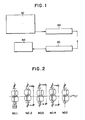
- a rotary straightener 20 is arranged downstream of a rolled pipe cooling bed 10 and a nondestructive inspection device 30 is arranged downstream of the rotary straightener 20.
- a pipe cutter 40 is arranged downstream of the nondestructive inspection device 30.
- the nondestructive inspection device 30 is composed of a leakage flux detector; a thickness meter which may be an electromagnetic supersonic thickness meter or a supersonic thickness meter; and a meter which measures the outside diameter of the pipe.
- the detecting capacity of the device is 192 m/min.
- the cutter having a cutting grinder can cut the plural pipes in one cutting cycle which promotes cutting efficiency and cutting accuracy, and minimises burring.
- the uninspected ends of the pipes are included in the crop ends.
- a high speed straightener having five stands and five pairs of rolls is utilized in the straightening.
- the rotary straightener is composed of five stands each of which incorporates two concave rolls skewed as for the pass line. The top and bottom rolls are skewed at the same absolute value of angle as for the pass line but in the positive and negative direction. As the rolls are rotated at the same speed, the pipe is spirally moved towards the delivery side.
- the clearances between the top and the bottom rolls are set smaller than the outside diameter of the pipe to apply a plastic deformation.
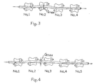
- the middle points of the clearances of the rolls at No.1, No.4 and No.5 are on the pass line.
- the middle points of the clearances of the rolls at No.2 and No.3 are off the pass line which is called the offset of the rotary straightener.
- the rate of rotation of the motor which drives the roll may be increased.
- the rotational speed of the pipe increases, which gives rise to vibration of the pipe and may break the pipe.
- the area of contact of the pipe with the rolls is decreased, which reduces the plastic deformation of the pipe, which is needed to straighten the pipe.
- the rolls of No.1, No.3 and No.4 stands are on the line, or the middle point of the clearance between the top and the bottom roll of a stand on the pass line.
- the rolls of No.2 stand are in an offset position.
- the straightening deformation is carried out be a single bending with the maximum offset of d max .
- the rolls of No.1, No.4 and No.5 are on the line and the rolls of No.2 and No.3 are in offset positions.
- the quantity of the maximum offset can be increased without applying an excessive offset on a single stand which may cause a spirally shaped defect on the surface of the pipes.
- the number of the stands of the rotary straightener is not limited to five but may be more than five. However when the number is increased, the chance of defect generation and the investment and the maintenance cost are increased. Therefore the number is limited to seven.
- the distance between adjacent stands is preferably from 750 to 850 mm.
- the distance is more than 850 mm, the leading end of the pipe is seized only with difficulty by the rolls.
- the distance is less than 750 mm, a severe enough bending is difficult to impose on the pipes. Therefore the distance is determined to be from 750 to 850 mm.
- range of outer diameters of the pipe wherein the invention is practicable is from 25.4 to 153.7 mm.
- the angle of the rolls in a range of from 35° to 50°. are on the skew angle is less than 35°, the rotational speed of the roll is excessive and the pipe wall may be cut through during its straightening.
- the skew angle is more than 50°, the area of contact of the pipe with the rolls is so low that a reasonable plastic deformation cannot be achieved.
- the translational speed of advance of the pipes is preferably no more than 4.0 m/sec., since when the rotational speed of the pipe at the rotary straightener is over 3000 rpm, it may cause the breakage of the pipe even when the skew angle of the rolls is set as 50°.
- the length of the pipes there is no limitation.
- the upper limit of the length of the pipes is 45 m. However it may be 100 m or more. It depends on the overall capacity of the rolling mills.
Landscapes
- Engineering & Computer Science (AREA)
- Mechanical Engineering (AREA)
- Metal Extraction Processes (AREA)
Applications Claiming Priority (4)
| Application Number | Priority Date | Filing Date | Title |
|---|---|---|---|
| JP30192389A JPH03165927A (ja) | 1989-11-22 | 1989-11-22 | 小径長尺管の高速矯正機 |
| JP301923/89 | 1989-11-22 | ||
| JP301922/89 | 1989-11-22 | ||
| JP30192289A JPH03165926A (ja) | 1989-11-22 | 1989-11-22 | 長尺鋼管の精整設備 |
Publications (2)
| Publication Number | Publication Date |
|---|---|
| EP0431775A2 true EP0431775A2 (de) | 1991-06-12 |
| EP0431775A3 EP0431775A3 (en) | 1991-07-10 |
Family
ID=26562928
Family Applications (1)
| Application Number | Title | Priority Date | Filing Date |
|---|---|---|---|
| EP19900312467 Withdrawn EP0431775A3 (en) | 1989-11-22 | 1990-11-15 | Method of continuous finishing of pipe |
Country Status (1)
| Country | Link |
|---|---|
| EP (1) | EP0431775A3 (de) |
Cited By (1)
| Publication number | Priority date | Publication date | Assignee | Title |
|---|---|---|---|---|
| EP2587206A4 (de) * | 2010-06-28 | 2014-10-08 | Nippon Steel & Sumitomo Metal Corp | Wärmeübertragungsrohr für dampferzeuger und herstellungsverfahren dafür |
Family Cites Families (6)
| Publication number | Priority date | Publication date | Assignee | Title |
|---|---|---|---|---|
| US3207289A (en) * | 1963-04-29 | 1965-09-21 | United States Steel Corp | Apparatus for delivering pipe lengths sidewise as discharged from rotary straightener or the like |
| JPS5744624U (de) * | 1980-08-21 | 1982-03-11 | ||
| US4494394A (en) * | 1981-07-06 | 1985-01-22 | Nilsson Einar W | Straightening machines and methods |
| DE3441537A1 (de) * | 1984-11-14 | 1986-05-15 | Th. Kieserling & Albrecht Gmbh & Co, 5650 Solingen | Schraegrollenrichtmaschine mit mehr als 2 richtrollen |
| US4663955A (en) * | 1986-02-18 | 1987-05-12 | Roman Engineering Company, Inc. | Apparatus for straightening tubing |
| DE3729619A1 (de) * | 1987-09-04 | 1989-03-16 | Reika Werk Gmbh Maschf | Verfahren und einrichtung zum richten von laengsverschieblichen und um ihre laengsachse sich drehenden rohren |
-
1990
- 1990-11-15 EP EP19900312467 patent/EP0431775A3/en not_active Withdrawn
Cited By (2)
| Publication number | Priority date | Publication date | Assignee | Title |
|---|---|---|---|---|
| EP2587206A4 (de) * | 2010-06-28 | 2014-10-08 | Nippon Steel & Sumitomo Metal Corp | Wärmeübertragungsrohr für dampferzeuger und herstellungsverfahren dafür |
| US10488038B2 (en) | 2010-06-28 | 2019-11-26 | Nippon Steel Corporation | Method for producing a heat transfer tube for steam generator using drawing, solution heat treatment, and straightening |
Also Published As
| Publication number | Publication date |
|---|---|
| EP0431775A3 (en) | 1991-07-10 |
Similar Documents
| Publication | Publication Date | Title |
|---|---|---|
| CN112570449B (zh) | 一种高效的双机架双剪切线直通中厚板生产线及生产方法 | |
| RU2057601C1 (ru) | Способ горячей прокатки стальной полосы и установка для его осуществления | |
| US20020062672A1 (en) | Pipe formed by bending rolls | |
| JPH0790241B2 (ja) | 条鋼の圧延方法 | |
| US4191041A (en) | Rolling mills | |
| EP0431775A2 (de) | Verfahren zur kontinuerlichen Endbearbeitung von Rohren | |
| WO2021063363A1 (zh) | 一种用于单剪切线的钢板双预堆垛系统及其堆垛方法 | |
| JPS594902A (ja) | 円形断面金属材の製造方法 | |
| KR20130138810A (ko) | 연속적 파이프 압연기에서 이음매 없는 열간 압연 파이프를 생산하기 위한 방법 | |
| JPH1133619A (ja) | 細物棒鋼の製造方法および製造装置 | |
| RU2012431C1 (ru) | Способ прокатки квадратных заготовок | |
| US4378687A (en) | Method for rolling H-sections in continuous mill | |
| JP3075385B2 (ja) | 熱間圧延材の表面傷除去方法 | |
| CN117483434A (zh) | 提高飞剪切头精度及改善倍尺分段弯曲的方法及轧制工艺 | |
| JP3080090B1 (ja) | 継目無管の圧延方法 | |
| JP4871250B2 (ja) | 条鋼の圧延方法 | |
| SU1727943A1 (ru) | Профилегибочный агрегат | |
| EP0623403B1 (de) | Verfahren zum herstellen geschweisster röhren und formvorrichtung dazu | |
| JPH0344844B2 (de) | ||
| SU1585025A1 (ru) | Способ получени профилей | |
| SU1068186A1 (ru) | Планетарный прокатный стан | |
| RU1782682C (ru) | Способ прокатки пр моугольных заготовок | |
| JP2019084564A (ja) | 熱間圧延方法、及び熱間圧延機列 | |
| EP2837435B1 (de) | Kaltwalzverfahren für nahtloses rohr | |
| JPS6123506A (ja) | 継目無鋼管圧延機における曲がり防止方法 |
Legal Events
| Date | Code | Title | Description |
|---|---|---|---|
| PUAI | Public reference made under article 153(3) epc to a published international application that has entered the european phase |
Free format text: ORIGINAL CODE: 0009012 |
|
| PUAL | Search report despatched |
Free format text: ORIGINAL CODE: 0009013 |
|
| 17P | Request for examination filed |
Effective date: 19901127 |
|
| AK | Designated contracting states |
Kind code of ref document: A2 Designated state(s): DE FR GB IT |
|
| AK | Designated contracting states |
Kind code of ref document: A3 Designated state(s): DE FR GB IT |
|
| 17Q | First examination report despatched |
Effective date: 19930211 |
|
| STAA | Information on the status of an ep patent application or granted ep patent |
Free format text: STATUS: THE APPLICATION IS DEEMED TO BE WITHDRAWN |
|
| 18D | Application deemed to be withdrawn |
Effective date: 19930622 |