EP0431777A1 - Abdeckung für Gräben - Google Patents
Abdeckung für Gräben Download PDFInfo
- Publication number
- EP0431777A1 EP0431777A1 EP90312505A EP90312505A EP0431777A1 EP 0431777 A1 EP0431777 A1 EP 0431777A1 EP 90312505 A EP90312505 A EP 90312505A EP 90312505 A EP90312505 A EP 90312505A EP 0431777 A1 EP0431777 A1 EP 0431777A1
- Authority
- EP
- European Patent Office
- Prior art keywords
- cover
- trench
- adjacent
- assembly
- hook
- Prior art date
- Legal status (The legal status is an assumption and is not a legal conclusion. Google has not performed a legal analysis and makes no representation as to the accuracy of the status listed.)
- Granted
Links
- 230000000284 resting effect Effects 0.000 claims abstract description 8
- 230000013011 mating Effects 0.000 claims abstract description 3
- 125000006850 spacer group Chemical group 0.000 claims description 7
- 229910000831 Steel Inorganic materials 0.000 claims description 6
- 239000002184 metal Substances 0.000 claims description 6
- 239000010959 steel Substances 0.000 claims description 6
- 239000000463 material Substances 0.000 claims description 5
- 239000004033 plastic Substances 0.000 claims description 4
- 229920003023 plastic Polymers 0.000 claims description 4
- 210000002105 tongue Anatomy 0.000 claims description 3
- 239000002990 reinforced plastic Substances 0.000 claims description 2
- 230000001419 dependent effect Effects 0.000 claims 1
- 230000002787 reinforcement Effects 0.000 claims 1
- 238000009432 framing Methods 0.000 description 4
- 239000010426 asphalt Substances 0.000 description 1
- 230000007797 corrosion Effects 0.000 description 1
- 238000005260 corrosion Methods 0.000 description 1
- 238000009408 flooring Methods 0.000 description 1
- 230000004048 modification Effects 0.000 description 1
- 238000012986 modification Methods 0.000 description 1
- 238000007493 shaping process Methods 0.000 description 1
- XLYOFNOQVPJJNP-UHFFFAOYSA-N water Substances O XLYOFNOQVPJJNP-UHFFFAOYSA-N 0.000 description 1
Images

Classifications
-
- E—FIXED CONSTRUCTIONS
- E03—WATER SUPPLY; SEWERAGE
- E03F—SEWERS; CESSPOOLS
- E03F5/00—Sewerage structures
- E03F5/04—Gullies inlets, road sinks, floor drains with or without odour seals or sediment traps
- E03F5/06—Gully gratings
-
- E—FIXED CONSTRUCTIONS
- E02—HYDRAULIC ENGINEERING; FOUNDATIONS; SOIL SHIFTING
- E02D—FOUNDATIONS; EXCAVATIONS; EMBANKMENTS; UNDERGROUND OR UNDERWATER STRUCTURES
- E02D17/00—Excavations; Bordering of excavations; Making embankments
- E02D17/06—Foundation trenches ditches or narrow shafts
- E02D17/10—Covering trenches for foundations
Definitions
- This invention relates to a cover for temporarily covering a trench in a thoroughfare such as a road or footpath, e.g. overnight until work restarts.
- Trench covers are already in use which consist in elongate plates, usually of steel, which are laid over the trench with the covers being supported by the ground on opposite sides of the trench. Normally a number of such plate covers are used, with the oppositely facing ends being in abutment.
- the problem with such plate covers is that, even though they are relatively heavy they can . be moved lengthwise and transversely of the trench by vibration imparted by the movement of traffic (vehicles or people) over the plate covers which can result in dangerous gaps occurring therebetween and consequentially the possibility of accidents. If the transverse movements are too great there is the risk that one or more plate covers will be tipped into the trench.
- the work persons can either inset the covers in the road or path surface or use rubble or asphalt to provide stops. Even when such precautions are taken, these plate covers can still be worked loose, e.g. by heavy vehicular traffic.
- Each cover comprises several individual grates which are arranged side by side lengthwise of the drain with one end of each grate being supported on the metal framing by an outwardly projecting lip and with the other end of each grate being supported by means of two lateral lugs extending from opposite sides respectively of each grate and engaging in correspondingly shaped notches of each two adjacent grates, with the lugs and notches lying within the general plane of the grates.
- a respective lateral lug engages on the framing to support the ends of the cover. Assembly and disassembly is by longitudinal movement into lug and notch engaging and disengaging positions. A removable key grate without lugs and notches is used to lock the whole assembly in position. Without the framing and key grate the individual gates would move lengthwise, thus making this cover unsuitable for a temporary trench cover as it would suffer from the same disadvantages of the known trench covers.
- the main object of the present invention is to provide a cover for temporarily covering a trench and in which the aforesaid disadvantages are minimized or avoided.
- the present invention consists in a cover for temporarily covering a trench, e.g. in a thoroughfare such as a road or a footpath, by extending over, and resting on the ground on opposite sides respectively of, the trench, the cover being releasably engageable with another adjacent cover in such a manner that when the covers are engaged in a ground resting position to form an assembly of covers, one cover of the assembly can be disengaged from an adjacent cover only by moving a cover out of the general plane of the assembly.
- a cover for temporarily covering a trench, e.g. in a thoroughfare such as a road or a footpath, by extending over, and resting on the ground on opposite sides respectively of, the trench, the cover being releasably engageable with another adjacent cover in such a manner that when the covers are engaged in a ground resting position to form an assembly of covers, one cover of the assembly can be disengaged from an adjacent cover only by moving a cover out of the general plane of the assembly.
- the releasable engagement also prevents or minimises vibration engendered lateral movements occuring between adjacent covers of the assembly.
- the releasable engagement means is preferably of sufficient width that, no matter how far the cover assembly is pushed in any one lateral direction, the side of the releasable engagement on one side of the trench will abut against the trench wall on that side before the opposite side of the cover assembly is pushed clear of the adjacent wall of the trench on that opposite side.
- the distance between the lateral edge of the cover and the wall of the trench on one side should be chosen to be greater than the distance between the wall of the trench and the releasable engagement on the other side.
- any cover i.e. an intermediate or end cover
- any cover can be picked up to release it from adjacent covers, preferably to improve security for example
- the nature of the releasable engagement is such that one cover can only be disengaged from the adjacent cover by picking up a cover at a free end of the assembly, it being impossible to remove a cover from an intermediate position in the assembly.
- the present invention consists in a cover for temporarily covering a trench by extending over, and resting on the ground on opposite sides respectively of, the trench, said cover including a cover member provided with releasable engagement means comprising male and female latching members depending from opposite end regions respectively of the cover member.
- the male latching member is a hook-shaped lug which mates with a female latching member in the form of an apertured lug on an adjacent cover.
- the aperture may be a slot or a laterally opening recess.
- the height of the aperture is such that the free end of the hook can be passed through the aperture to latch or unlatch the hook shaped lug from the aperture of an apertured lug on an adjacent cover and is conveniently disposed so that a hook portion of the hooked shaped lug lies adjacent or touches the bottom of the aperture and abuts against an outer surface of the apertured lug.
- the cover member In order to release an end cover from an adjacent cover, i.e. unlatch the hook-shaped lug from its enlatchment with an apertured lug of the adjacent cover, the cover member is provided with a key hole which can be engaged with a lifting hook to lift the end cover out of the general plane of the cover so that the free end of the hook-shaped lug can be pulled through the aperture in the apertured lug and the cover lifted away from the trench.
- the apertured lug is preferably shaped laterally to receive spacer elements to laterally extend the width of the lug.
- the lateral shaping may be recesses, eg in the form of grooves which receive tongues on the spacer elements.
- the covers which are conveniently of rectangular shape may be made in a number of widths, e.g. 160 mm, 190 mm and 220 mm to cater for different widths of trench. Ideally the width of the cover should be no more than 40 mm greater than the width of the trench. Whilst the length of the covers can be as desired, a suitable length is 500 mm.
- the cover may be made of any suitable material, such as steel, consistent with providing the requisite strength to support heavy vehicles passing over it: but preferably in order to reduce weight and protect any metal from corrosion, e.g. steel from rusting, the whole cover including the cover member and the releasable engagement is made of metal reinforced plastics.
- the cover has a pressed-steel core or base around which the plastics material is moulded, with the cover member being preferably of corrugated shape to increase strength.
- the cover advantageously has tapering lateral edges to form ramps, and optionally to increase grip, the cover is provided with a tread pattern on its top surface.
- the tread pattern may have variations in depth.
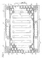
- a cover which is generally indicated at 1 for temporarily covering a trench 2 e.g. in a road 3, by a cover member 4 thereof extending over, and resting on the ground on opposite sides respectively of the trench.
- the cover 1 is releasably engageable with other adjacent covers 1a and 1b, partly shown in chain lines in Fig. 3, by means of male and female latching members in the form of hook-shaped and apertured lugs 5 and 6 respectively to form an assembly of covers 7 of which one cover of the assembly can be disengaged from an adjacent cover only by moving a cover out of the general plane of the assembly.
- the lugs 5 and 6 depend from opposite end regions 8 and 9 respectively of the cover member 4.
- the cover member 4 has tapering lateral edges forming ramps 10 to facilitate the passage of traffic over the cover when in position covering a trench.
- the top surface of the cover member 4 including the ramps 10 and the area 11 lying between the ramps is provided with a tread pattern 12 which is at a minimum as indicated by the reference 13 and at a maximum, as indicated by the reference 14.
- the cover has a pressed steel base or core 15 extending throughout the cover member 4 and the lugs 5 and 6, with the base 15 in the region of the cover member 4 being corrugated to increase strength.
- a plastics material 16 is moulded with the plastics material providing the ramps 10 and the tread pattern 12.
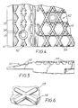
- the hook-shaped lug 5 has a straight portion 20 depending perpendicularly from the end region 8 and a hook portion 21 projecting outwardly beyond the end region 8.
- the apertured lug 6 Depending perpendicularly from the other end region 9 of the cover member 4 is the apertured lug 6 whose aperture is in the form of an elongate slot 22 extending tranversely of the cover 1, as will be apparent from Fig. 2.
- the aperture 22 has a height such as to allow the cover 1 to be engaged with another such cover in a manner to be described.
- the lug 6 has lateral recesses in the form of grooves 23 for receiving the tongues 24 of at least one spacer element (only one shown in chain lines at 25). The or each spacer element laterally extends the width of the lug 6 to enable a narrower width cover to be positioned over a slightly wider trench than usual, as indicated by the chain lines 26 to avoid the cover from being tipped into the wider trench.
- a key hole 27 is provided in the cover member 4 adjacent the end region 8 with the hook-shaped lug 5, for use with a lifting hook (not shown).
- the width of the covers 1 1a and 1b is chosen such that the distances (y) between the edge or wall of the trench and the edge of the cover on one side is greater than the distance (z), between the side 28 of the lug 6 and the edge or wall of the trench on the other side. If these distances are not right then one or two spacer elements 25 can be used. Then the cover 1 is brought to the trench and the end region 8 tilted downwards so that the hook portion 21 of the hook-shaped lug 5 can be passed through the aperture 22a in the lug 6a.
- the end region 9 of the cover 1 is lowered so that the horizontal part 29 of the hook portion touches, or lies close to the bottom of the aperture 22a and the vertical part 30 of the hook portion 21 abuts against the lug 6a beneath the aperture 22a to latch the two covers 1a and 1b together.
- the last cover 1b having a hook-shaped lug 5b which mates with the aperture 22 of the cover 1 is then latched to the cover 1 in a similar manner to that described for covers 1 and 1a, to complete the cover assembly 7 for covering the trench 2.
- the nature of the interengaging lugs is such that only small non-dangerous gaps 31 are left between the adjacent ends of the covers. It will be apparent from Fig. 3 that the intermediate cover cannot be moved in view of the enlatchment of the lugs 5,6a and 5b, 6. It is only possible to remove the covers from one end of the assembly, that being the end in which an apertured lug is at the end of the cover assembly, in this case apertured lug (not shown) of the cover 1b. Thus the cover 1b is unlatched from the cover 1 in the same manner as the cover 1 was unlatched from the cover 1a.
- the cover could be of oblong shape, it could be square.
- the shape of the mating lugs 5 and 6 could be varied, for example,by having an upwardly facing hook-shaped lug constituting the female member which depends from, and projects beyond, one end region of the cover, and of which the hook is engageable by a plate-shaped lug, constituting the male member, depending from the other end region of another such cover.
- the upwardly facing hook-shaped lug could be of channel form with the plate-shaped lug engaging in the channel or the upwardly facing hook-shaped lug could have an aperture, eg a slot, in which the plate shaped lug engages.
Landscapes
- Engineering & Computer Science (AREA)
- Mining & Mineral Resources (AREA)
- Life Sciences & Earth Sciences (AREA)
- General Life Sciences & Earth Sciences (AREA)
- Paleontology (AREA)
- Civil Engineering (AREA)
- General Engineering & Computer Science (AREA)
- Structural Engineering (AREA)
- Health & Medical Sciences (AREA)
- Hydrology & Water Resources (AREA)
- Public Health (AREA)
- Water Supply & Treatment (AREA)
- Sewage (AREA)
Applications Claiming Priority (2)
| Application Number | Priority Date | Filing Date | Title |
|---|---|---|---|
| GB8927346A GB2238815B (en) | 1989-12-04 | 1989-12-04 | Cover for trenches |
| GB8927346 | 1989-12-04 |
Publications (2)
| Publication Number | Publication Date |
|---|---|
| EP0431777A1 true EP0431777A1 (de) | 1991-06-12 |
| EP0431777B1 EP0431777B1 (de) | 1993-07-21 |
Family
ID=10667371
Family Applications (1)
| Application Number | Title | Priority Date | Filing Date |
|---|---|---|---|
| EP19900312505 Expired - Lifetime EP0431777B1 (de) | 1989-12-04 | 1990-11-16 | Abdeckung für Gräben |
Country Status (3)
| Country | Link |
|---|---|
| EP (1) | EP0431777B1 (de) |
| DE (1) | DE69002310T2 (de) |
| GB (1) | GB2238815B (de) |
Cited By (8)
| Publication number | Priority date | Publication date | Assignee | Title |
|---|---|---|---|---|
| EP0620330A1 (de) * | 1993-03-12 | 1994-10-19 | FRIATEC AG Keramik- und Kunststoffwerke | Stegelement für begehbaren Abdeckrost |
| EP0736632A1 (de) * | 1995-04-04 | 1996-10-09 | British Gas plc | Provisorische Abdeckplatte für einen Graben |
| ES2142217A1 (es) * | 1997-02-11 | 2000-04-01 | Palomo Garcia Meliton | Sumidero o imbornal hermetico con apertura y cierre automaticos. |
| WO2001021898A1 (en) | 1999-09-17 | 2001-03-29 | David Vincent Byrne | A trench cover element |
| GB2374371A (en) * | 2001-03-06 | 2002-10-16 | Quantum Covers Ltd | Trench cover for use with permanently accessible trenches |
| WO2002084033A1 (en) | 2001-04-17 | 2002-10-24 | David Vincent Byrne | A trench cover |
| FR2903436A1 (fr) * | 2006-07-10 | 2008-01-11 | Alicote Sarl | Element utilise pour l'evacuation des eaux pluviales |
| EP2000592A1 (de) * | 2007-06-08 | 2008-12-10 | Ballast Nedam Infra B.V. | Verfahren zum Anbringen/Entfernen einer Fuge und Vorrichtung zum Abdecken dieser Fuge |
Families Citing this family (7)
| Publication number | Priority date | Publication date | Assignee | Title |
|---|---|---|---|---|
| GB9318746D0 (en) * | 1993-09-09 | 1993-10-27 | M W Polymer Products Limited | Platform assembly |
| GB2305954B (en) * | 1995-10-04 | 2000-02-23 | British Gas Plc | Trench covers |
| GB9700587D0 (en) * | 1997-01-14 | 1997-03-05 | Tarmac Uk Ltd | Temporary covers for trenches and other excavations |
| GB9905871D0 (en) * | 1999-03-16 | 1999-05-05 | Asg Contractors Ltd | Improved tile cover |
| GB2405895B (en) * | 2003-09-09 | 2006-08-16 | Buzz Inc Ltd | A cover for temporarily covering a trench |
| KR100771999B1 (ko) * | 2004-05-20 | 2007-10-31 | 김상돈 | 그레이팅 |
| GB2448371B (en) * | 2007-04-14 | 2012-03-07 | Oxford Plastic Sys Ltd | Trench cover |
Citations (7)
| Publication number | Priority date | Publication date | Assignee | Title |
|---|---|---|---|---|
| DE18459C (de) * | W. REDOALL in Finsburg (England) | Neuerungen an Einfassungen der Fufswege | ||
| FR865707A (fr) * | 1940-02-05 | 1941-05-31 | Aire d'atterrissage pour avions | |
| USRE26366E (en) * | 1968-04-09 | Interlocking grating and framing system for trench drains | ||
| GB1249914A (en) * | 1969-01-17 | 1971-10-13 | Oswald Burgess | Trench cover |
| EP0035594A2 (de) * | 1980-03-08 | 1981-09-16 | Passavant-Werke Ag | Abflussrinne mit mehrteiligem Einlaufrost |
| EP0147050A1 (de) * | 1983-11-26 | 1985-07-03 | John Reginald Newton | Zusammengesetzter Gegenstand |
| FR2581587A1 (fr) * | 1985-05-10 | 1986-11-14 | Allibert Sa | Procede de fabrication de parois en matiere plastique de grandes dimensions, et de planeite amelioree, et produits obtenus |
-
1989
- 1989-12-04 GB GB8927346A patent/GB2238815B/en not_active Expired - Fee Related
-
1990
- 1990-11-16 DE DE1990602310 patent/DE69002310T2/de not_active Expired - Fee Related
- 1990-11-16 EP EP19900312505 patent/EP0431777B1/de not_active Expired - Lifetime
Patent Citations (7)
| Publication number | Priority date | Publication date | Assignee | Title |
|---|---|---|---|---|
| DE18459C (de) * | W. REDOALL in Finsburg (England) | Neuerungen an Einfassungen der Fufswege | ||
| USRE26366E (en) * | 1968-04-09 | Interlocking grating and framing system for trench drains | ||
| FR865707A (fr) * | 1940-02-05 | 1941-05-31 | Aire d'atterrissage pour avions | |
| GB1249914A (en) * | 1969-01-17 | 1971-10-13 | Oswald Burgess | Trench cover |
| EP0035594A2 (de) * | 1980-03-08 | 1981-09-16 | Passavant-Werke Ag | Abflussrinne mit mehrteiligem Einlaufrost |
| EP0147050A1 (de) * | 1983-11-26 | 1985-07-03 | John Reginald Newton | Zusammengesetzter Gegenstand |
| FR2581587A1 (fr) * | 1985-05-10 | 1986-11-14 | Allibert Sa | Procede de fabrication de parois en matiere plastique de grandes dimensions, et de planeite amelioree, et produits obtenus |
Cited By (12)
| Publication number | Priority date | Publication date | Assignee | Title |
|---|---|---|---|---|
| EP0620330A1 (de) * | 1993-03-12 | 1994-10-19 | FRIATEC AG Keramik- und Kunststoffwerke | Stegelement für begehbaren Abdeckrost |
| EP0736632A1 (de) * | 1995-04-04 | 1996-10-09 | British Gas plc | Provisorische Abdeckplatte für einen Graben |
| ES2142217A1 (es) * | 1997-02-11 | 2000-04-01 | Palomo Garcia Meliton | Sumidero o imbornal hermetico con apertura y cierre automaticos. |
| WO2001021898A1 (en) | 1999-09-17 | 2001-03-29 | David Vincent Byrne | A trench cover element |
| GB2370063A (en) * | 1999-09-17 | 2002-06-19 | David Vincent Byrne | A trench cover element |
| GB2370063B (en) * | 1999-09-17 | 2004-01-14 | David Vincent Byrne | A trench cover element |
| US6722814B2 (en) | 1999-09-17 | 2004-04-20 | David Vincent Byrne | Trench cover element |
| GB2374371A (en) * | 2001-03-06 | 2002-10-16 | Quantum Covers Ltd | Trench cover for use with permanently accessible trenches |
| WO2002084033A1 (en) | 2001-04-17 | 2002-10-24 | David Vincent Byrne | A trench cover |
| FR2903436A1 (fr) * | 2006-07-10 | 2008-01-11 | Alicote Sarl | Element utilise pour l'evacuation des eaux pluviales |
| EP2000592A1 (de) * | 2007-06-08 | 2008-12-10 | Ballast Nedam Infra B.V. | Verfahren zum Anbringen/Entfernen einer Fuge und Vorrichtung zum Abdecken dieser Fuge |
| NL1033956C2 (nl) * | 2007-06-08 | 2008-12-15 | Ballast Nedam Infra B V | Werkwijze voor het aanbrengen/verwijderen van een voeg in een uitsparing tussen delen van een wegdek en een inrichting voor het daarbij afdekken. |
Also Published As
| Publication number | Publication date |
|---|---|
| GB2238815B (en) | 1994-02-16 |
| EP0431777B1 (de) | 1993-07-21 |
| DE69002310D1 (de) | 1993-08-26 |
| DE69002310T2 (de) | 1994-01-05 |
| GB2238815A (en) | 1991-06-12 |
| GB8927346D0 (en) | 1990-01-31 |
Similar Documents
| Publication | Publication Date | Title |
|---|---|---|
| EP0431777A1 (de) | Abdeckung für Gräben | |
| US4826351A (en) | Grid plate of plastic material | |
| US4917532A (en) | Grid plate | |
| US4113400A (en) | Impact resistant tongue-and-groove coupling for highway traffic barricades | |
| EP1212492B1 (de) | Grabendeckelelement | |
| EP0551347B1 (de) | Landschaftsgestaltender block | |
| EP2959064B1 (de) | Vorgefertigtes nivellierungssegment unter einer verkehrsschranke über einem erdstützwandsystem | |
| US20020170259A1 (en) | Interlocking sidewalk block system | |
| US20120207543A1 (en) | Embedment plate for pedestrian walkways with reinforced projections | |
| US20110142539A1 (en) | Member for temporarily restoring road surface and method for temporarily restoring road surface | |
| RS50733B (sr) | Rešetka za zatvaranje kanalizacionih otvora i slično | |
| US4443981A (en) | Concrete form system | |
| US5179752A (en) | Cover for trenches | |
| GB2231904A (en) | Kerb/drainage channel | |
| US5320445A (en) | Grate riser assembly for use with catch basins and the like | |
| KR200339448Y1 (ko) | 보강토 옹벽용 블록 | |
| JP3475906B2 (ja) | 自由勾配型函渠側溝 | |
| JP4564020B2 (ja) | 縁石ブロック | |
| GB2204076A (en) | Manhole cover plates | |
| JP2003328426A (ja) | 排水溝への突片付き溝蓋の取付け構造 | |
| JPH08128005A (ja) | 仮設道路用マット | |
| KR102169385B1 (ko) | 조립식 보도 낮춤턱 설치방법 및 조립식 보도 낮춤턱 | |
| JPH0439336Y2 (de) | ||
| JP3054705U (ja) | 電線類地中化特殊部の開閉装置 | |
| CA1082969A (en) | Tongue-and-groove coupling for highway traffic barricade |
Legal Events
| Date | Code | Title | Description |
|---|---|---|---|
| PUAI | Public reference made under article 153(3) epc to a published international application that has entered the european phase |
Free format text: ORIGINAL CODE: 0009012 |
|
| AK | Designated contracting states |
Kind code of ref document: A1 Designated state(s): BE DE FR GB IT NL |
|
| 17P | Request for examination filed |
Effective date: 19910514 |
|
| 17Q | First examination report despatched |
Effective date: 19911203 |
|
| GRAA | (expected) grant |
Free format text: ORIGINAL CODE: 0009210 |
|
| AK | Designated contracting states |
Kind code of ref document: B1 Designated state(s): BE DE FR GB IT NL |
|
| ITF | It: translation for a ep patent filed | ||
| REF | Corresponds to: |
Ref document number: 69002310 Country of ref document: DE Date of ref document: 19930826 |
|
| ET | Fr: translation filed | ||
| PLBE | No opposition filed within time limit |
Free format text: ORIGINAL CODE: 0009261 |
|
| STAA | Information on the status of an ep patent application or granted ep patent |
Free format text: STATUS: NO OPPOSITION FILED WITHIN TIME LIMIT |
|
| 26N | No opposition filed | ||
| PGFP | Annual fee paid to national office [announced via postgrant information from national office to epo] |
Ref country code: FR Payment date: 19981008 Year of fee payment: 9 |
|
| PGFP | Annual fee paid to national office [announced via postgrant information from national office to epo] |
Ref country code: BE Payment date: 19981022 Year of fee payment: 9 |
|
| PGFP | Annual fee paid to national office [announced via postgrant information from national office to epo] |
Ref country code: DE Payment date: 19981027 Year of fee payment: 9 |
|
| PGFP | Annual fee paid to national office [announced via postgrant information from national office to epo] |
Ref country code: NL Payment date: 19981028 Year of fee payment: 9 |
|
| PG25 | Lapsed in a contracting state [announced via postgrant information from national office to epo] |
Ref country code: BE Free format text: LAPSE BECAUSE OF NON-PAYMENT OF DUE FEES Effective date: 19991130 |
|
| BERE | Be: lapsed |
Owner name: BG PUBLIC LIMITED COMPANY Effective date: 19991130 |
|
| PG25 | Lapsed in a contracting state [announced via postgrant information from national office to epo] |
Ref country code: NL Free format text: LAPSE BECAUSE OF NON-PAYMENT OF DUE FEES Effective date: 20000601 |
|
| PG25 | Lapsed in a contracting state [announced via postgrant information from national office to epo] |
Ref country code: FR Free format text: LAPSE BECAUSE OF NON-PAYMENT OF DUE FEES Effective date: 20000731 |
|
| NLV4 | Nl: lapsed or anulled due to non-payment of the annual fee |
Effective date: 20000601 |
|
| PG25 | Lapsed in a contracting state [announced via postgrant information from national office to epo] |
Ref country code: DE Free format text: LAPSE BECAUSE OF NON-PAYMENT OF DUE FEES Effective date: 20000901 |
|
| REG | Reference to a national code |
Ref country code: FR Ref legal event code: ST |
|
| REG | Reference to a national code |
Ref country code: GB Ref legal event code: IF02 |
|
| PGFP | Annual fee paid to national office [announced via postgrant information from national office to epo] |
Ref country code: GB Payment date: 20021016 Year of fee payment: 13 |
|
| PG25 | Lapsed in a contracting state [announced via postgrant information from national office to epo] |
Ref country code: GB Free format text: LAPSE BECAUSE OF NON-PAYMENT OF DUE FEES Effective date: 20031116 |
|
| GBPC | Gb: european patent ceased through non-payment of renewal fee |
Effective date: 20031116 |
|
| PG25 | Lapsed in a contracting state [announced via postgrant information from national office to epo] |
Ref country code: IT Free format text: LAPSE BECAUSE OF NON-PAYMENT OF DUE FEES Effective date: 20051116 |