EP0431876A2 - Tête d'impression - Google Patents
Tête d'impression Download PDFInfo
- Publication number
- EP0431876A2 EP0431876A2 EP90313117A EP90313117A EP0431876A2 EP 0431876 A2 EP0431876 A2 EP 0431876A2 EP 90313117 A EP90313117 A EP 90313117A EP 90313117 A EP90313117 A EP 90313117A EP 0431876 A2 EP0431876 A2 EP 0431876A2
- Authority
- EP
- European Patent Office
- Prior art keywords
- head
- pins
- printer head
- yoke
- base plate
- Prior art date
- Legal status (The legal status is an assumption and is not a legal conclusion. Google has not performed a legal analysis and makes no representation as to the accuracy of the status listed.)
- Withdrawn
Links
Images


Classifications
-
- B—PERFORMING OPERATIONS; TRANSPORTING
- B41—PRINTING; LINING MACHINES; TYPEWRITERS; STAMPS
- B41J—TYPEWRITERS; SELECTIVE PRINTING MECHANISMS, i.e. MECHANISMS PRINTING OTHERWISE THAN FROM A FORME; CORRECTION OF TYPOGRAPHICAL ERRORS
- B41J2/00—Typewriters or selective printing mechanisms characterised by the printing or marking process for which they are designed
- B41J2/22—Typewriters or selective printing mechanisms characterised by the printing or marking process for which they are designed characterised by selective application of impact or pressure on a printing material or impression-transfer material
- B41J2/23—Typewriters or selective printing mechanisms characterised by the printing or marking process for which they are designed characterised by selective application of impact or pressure on a printing material or impression-transfer material using print wires
- B41J2/235—Print head assemblies
- B41J2/24—Print head assemblies serial printer type
Definitions
- the present invention relates to a printer head and more specifically to a printer head which is of simplified head construction without requiring a substantial increase in the head stroke.
- the printers have a printer head mounted in a printing section.
- An example of a conventional printer head is shown in Figure 1.
- This printer head consists of a yoke 1 for forming an electromagnetic circuit, a permanent magnet 2 secured to the yoke 1 , an electromagnetic coil 3 mounted close to the permanent magnet 2 , a base plate 4 mounted on the front of the yoke 1 , an armature 6 mounted to a leaf spring 5 clamped between the yoke 1 and the base plate 4 , and a print wire 7 attached to the front end of the armature 6 .
- the base plate 4 has almost at its center a forwardly projecting cylindrical wire holder 9 , which has a guide 8 at the front end and contains the print wire 7 therein.
- the magnet members 2 , 3 , leaf spring 5 , armature 6 and print wire 7 make up a print set and a plurality of the print sets are provided in a plane perpendicular to the center line 0 of the printer head in such a way that these sets are arranged in a circle at angles apart from each other.
- the same number of print wires 7 as that of the print sets are passed through the wire holder 9 to reach the outlet of the guide 8 . In this type of printer head, 24 print wires 7 for example are used.
- the front ends of these print wires 7 are held and lined at equal intervals in a vertical direction perpendicular to the direction of the printer head stroke in such a way that they will not come into contact with each other.
- very fine wires are used as the print wires 7 .
- these 24 print wires cover the height of one line of characters.
- electric current is not applied to the electromagnetic coil 3 , so that the armature 6 is attracted to the front surface of the yoke 1 by the action of the permanent magnet 2 .
- the leaf spring 5 is deflected rearwardly holding the print wires 7 at a retracted position (in a state shown in Figure 1).
- the electromagnetic coil 3 is energized to cancel out the magnetic flux of the permanent magnet 2 . This allows the armature 6 to rapidly part from the yoke surface by the recovery force of the leaf spring 5 attached to the armature 6 , causing the print wires 7 to advance forwardly.
- the front end of the print wire 7 abuts against a sheet of recording paper set on a platen (not shown).
- the armature 6 is again attracted to the surface of the yoke 1 by the permanent magnet 2 .
- the invention has been accomplished to overcome the above drawbacks, and its objective is to provide a printer head which is simple in structure and easy to manufacture.
- This is achieved by the characterising features of claim 1.
- the invention is further characterized in that short head pins are employed in elements that perform printing, that these head pins are arranged in two or more straight rows which are inclined at a specified angle to the direction of stroke of the printer head, and that a plurality of through-holes are formed in a base plate at positions corresponding to the head pins.
- the intervals between adjacent head pins can be increased without increasing the vertical dimension of the head pin installation space.
- the head pins are arranged in two or more straight rows, not in a single row, which are slightly inclined with respect to the direction of the printer head stroke, so that not only can a large number of head pins be accommodated in a space, which is small in the vertical direction, but also the printer head can be prevented from becoming large in the lateral size.
- print data for a plurality of characters are sent to the printer head in synchronism with the latter's motion to activate the head pins arranged in tilted rows.
- a character being printed by a head pin located at the front position with respect to the direction of the forward stroke of the printer head is staggered in the direction of printer head stroke from a character being printed by a head pin at the rear position.
- a character begins to be printed by the passage of a head pin, which is located at the foremost position with respect to the direction of the printer head stroke, and its printing is ended when the rearmost head pin passes the print position of the character.
- the first head pin starts printing any other character located in front of the character in question or has finished the printing of the line.
- This invention therefore, allows a relatively wide space for the head pins and their drive mechanisms while at the same time maintaining the dots printed by the head pins close enough to each other so that the dots fall in a small vertical space.
- Another advantage is that since the head pins are divided into two or more straight rows, an extra stroke of the printer head required to print a single line can be minimized.
- Figures 2 to 4 show one embodiment of a printer head according to this invention.
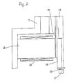
- Figure 2 is a cross section showing the construction of a print assembly in the printer head; and
- Figure 3 is a schematic diagram showing a part of the printer head as viewed from the front.
- the printer head of this embodiment consists of a yoke 11 to form an electromagnetic circuit; a permanent magnet 12 securely mounted to the yoke 11 ; an electromagnetic coil 13 wound on the permanent magnet 12 to form, together with the permanent magnet 12 , a magnetic drive member; a base plate 14 mounted on the front of the yoke 11 ; an armature 16 attached to a leaf spring 15 clamped between the yoke 11 and the base plate 14 ; and a head pin 17 for printing which is attached to the front of the armature 16 .
- the magnetic drive member made up of the permanent magnet 12 and the electromagnetic coil 13 , the leaf spring 15 , the armature 16 and the head pin 17 all combine to form a print assembly.
- a plurality of print assemblies (for example 24 assemblies) are installed at the back of the base plate 14 , as shown in Figure 3.
- the head pin 17 is formed of a rod member shorter than the conventional print wire 7 but which has a larger diameter than the print wire 7 , except at the front end which is pointed into a very small diameter.
- the number of head pins 17 corresponds to that of the print assemblies. They are divided into two rows of 12 head pins each (see Figure 3). Figure 3 shows the right half, viewed from the front, of the printer head in which upper and lower rows A1 , A2 of 12 head pins 17 are arranged. These rows of head pins 17 are lined parallel to each other and inclined at a small specified angle of ⁇ to the direction of printer head stroke or motion (for example, to the horizontal line H ).
- the base plate 14 is formed with through-holes 18 at positions corresponding to the head pins 17 so that the head pins 17 can be passed through the holes 18 .
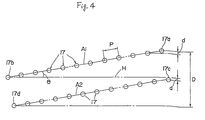
- Figure 4 schematically shows the arrangement of the head pins 17 .
- the head pins as a whole are fed toward the right during printing operation, i.e., the forward side is on the right and the backward side is on the left of the drawing.
- the head pins 17 are lined at equal intervals or pitches P . Since the rows A1 , A2 are inclined at an angle of ⁇ , there are vertical deviations between the adjacent head pins 17 . The vertical deviation between each head pins 17 is given by
- the junction point between the upper and lower rows A1 , A2 is correctly adjusted for the vertical deviation. That is, the vertical deviation between the last head pin 17b of the upper row A1 and the first head pin 17c of the lower row A2 is also set to d . Hence, the overall vertical distance D from the first head pin 17a to the last head pin 17d is expressed as
- the total length of the head pin rows is 23P if the two rows were arranged in one line. In other words, a row of head pins this long is accommodated in such a small vertical space.
- the drive mechanisms each consisting of the yoke 11 , electromagnetic coil 13 and leaf spring 15 are installed behind the base plate 14 in an almost elliptic arrangement.
- the head pins 17 can be formed of a rod member which is larger in diameter than the conventional print wires. Another advantage is that even when the head pins 17 are formed shorter than the conventional print wires, the adjacent drive members do not interfere with each other.
- the above-mentioned arrangement of the head pins 17 in the printer head of this embodiment is equivalent to installing a large number of head pins 17 (in the above case 24 pins) in a small vertical space. Since the head pins 17 are arranged not in a single straight row but in two rows (they may be arranged in three or more rows), the printer head can be made compact.
- the printer head is fed with print data for a plurality of characters in synchronism with the printer head motion to drive a plurality of head pins arranged in inclined rows.
- a character being printed by head pins 17a , 17c located at the front position with respect to the direction of the forward stroke of the printer head is staggered in the direction of printer head stroke from a character being printed by head pins 17b , 17d at the rear position.
- a character begins to be printed by the passage of the head pin 17c located at the foremost position and its printing is ended when the rearmost head pin 17b passes the print position of the character.
- the first head pin 17c starts printing any other character located in front of the character in question or has finished the printing of the line.
- the printing of one line of a document is carried out by activating a series of head pins 17 successively, from the first head pin 17c to the last head pin 17b , in synchronism with the motion of the printer head.
Landscapes
- Impact Printers (AREA)
Applications Claiming Priority (2)
| Application Number | Priority Date | Filing Date | Title |
|---|---|---|---|
| JP31470989A JPH03175054A (ja) | 1989-12-04 | 1989-12-04 | プリンタヘッド |
| JP314709/89 | 1989-12-04 |
Publications (2)
| Publication Number | Publication Date |
|---|---|
| EP0431876A2 true EP0431876A2 (fr) | 1991-06-12 |
| EP0431876A3 EP0431876A3 (en) | 1991-12-04 |
Family
ID=18056614
Family Applications (1)
| Application Number | Title | Priority Date | Filing Date |
|---|---|---|---|
| EP19900313117 Withdrawn EP0431876A3 (en) | 1989-12-04 | 1990-12-03 | Printer head |
Country Status (2)
| Country | Link |
|---|---|
| EP (1) | EP0431876A3 (fr) |
| JP (1) | JPH03175054A (fr) |
Cited By (1)
| Publication number | Priority date | Publication date | Assignee | Title |
|---|---|---|---|---|
| US6682233B2 (en) * | 2002-03-18 | 2004-01-27 | Toshiba Tec Kabushika Kaisha | Supporting structure of an armature of a wire dot printer head |
Families Citing this family (1)
| Publication number | Priority date | Publication date | Assignee | Title |
|---|---|---|---|---|
| JPH10138531A (ja) * | 1996-11-08 | 1998-05-26 | Hitachi Koki Co Ltd | ドットラインプリンタ |
Family Cites Families (4)
| Publication number | Priority date | Publication date | Assignee | Title |
|---|---|---|---|---|
| IL56669A0 (en) * | 1978-02-15 | 1979-05-31 | Nori Sinoto | Matrix printer |
| US4484519A (en) * | 1981-08-11 | 1984-11-27 | Citizen Watch Co. Ltd. | Stylus driving apparatus for printers |
| JPS5998868A (ja) * | 1982-11-29 | 1984-06-07 | Citizen Watch Co Ltd | インパクト型ドット印字ヘッドの製造方法 |
| US4527469A (en) * | 1983-04-15 | 1985-07-09 | Dataproducts Corporation | Dot matrix print actuator |
-
1989
- 1989-12-04 JP JP31470989A patent/JPH03175054A/ja active Pending
-
1990
- 1990-12-03 EP EP19900313117 patent/EP0431876A3/en not_active Withdrawn
Cited By (1)
| Publication number | Priority date | Publication date | Assignee | Title |
|---|---|---|---|---|
| US6682233B2 (en) * | 2002-03-18 | 2004-01-27 | Toshiba Tec Kabushika Kaisha | Supporting structure of an armature of a wire dot printer head |
Also Published As
| Publication number | Publication date |
|---|---|
| JPH03175054A (ja) | 1991-07-30 |
| EP0431876A3 (en) | 1991-12-04 |
Similar Documents
| Publication | Publication Date | Title |
|---|---|---|
| JPS6344551B2 (fr) | ||
| KR100628665B1 (ko) | 단일 전기자 조립체를 갖는 도트 매트릭스 인쇄 헤드와 그 작동 방법 | |
| US4423969A (en) | Print head | |
| US6513997B2 (en) | Wire dot printer head and wire dot printer using the same | |
| US4300845A (en) | Dot matrix print head | |
| CA1062957A (fr) | Tete d'impression amelioree | |
| EP0431876A2 (fr) | Tête d'impression | |
| US3835975A (en) | Printer head assembly | |
| GB2175853A (en) | Print head hammer mechanism | |
| US4669898A (en) | Dot matrix print head | |
| US4625638A (en) | Dot matrix line printer | |
| US4548521A (en) | Dot matrix print head | |
| JPS60500612A (ja) | ワイヤ・マトリクス・プリント・ヘッド | |
| US5846004A (en) | Impact print head | |
| US5263782A (en) | Print hammer arrangement in dot line printer minimizing number of hammers simultaneously fired | |
| EP0474254A1 (fr) | Tête d'impression par points à aiguilles | |
| US4859095A (en) | Printing head with current passing through the print wire | |
| EP0267720A2 (fr) | Guidage flexible du fil d'impression pour imprimante à matrice de points | |
| JP3565721B2 (ja) | 積層型ワイヤドット印字ヘッド | |
| US5083876A (en) | Print wire alignment in a wire dot printer | |
| JP3098496B2 (ja) | 印字ヘッド | |
| JP2902437B2 (ja) | 印字ヘッド | |
| JPH09201987A (ja) | ドットラインプリンタ | |
| JPS6116866A (ja) | 印字ヘツド | |
| JPS60187561A (ja) | シリアル型ドツトプリンタ |
Legal Events
| Date | Code | Title | Description |
|---|---|---|---|
| PUAI | Public reference made under article 153(3) epc to a published international application that has entered the european phase |
Free format text: ORIGINAL CODE: 0009012 |
|
| AK | Designated contracting states |
Kind code of ref document: A2 Designated state(s): DE FR GB IT SE |
|
| PUAL | Search report despatched |
Free format text: ORIGINAL CODE: 0009013 |
|
| AK | Designated contracting states |
Kind code of ref document: A3 Designated state(s): DE FR GB IT SE |
|
| 17P | Request for examination filed |
Effective date: 19920527 |
|
| 17Q | First examination report despatched |
Effective date: 19920730 |
|
| STAA | Information on the status of an ep patent application or granted ep patent |
Free format text: STATUS: THE APPLICATION IS DEEMED TO BE WITHDRAWN |
|
| 18D | Application deemed to be withdrawn |
Effective date: 19930928 |