EP0431913A2 - Cassettes à bande magnétique - Google Patents
Cassettes à bande magnétique Download PDFInfo
- Publication number
- EP0431913A2 EP0431913A2 EP90313189A EP90313189A EP0431913A2 EP 0431913 A2 EP0431913 A2 EP 0431913A2 EP 90313189 A EP90313189 A EP 90313189A EP 90313189 A EP90313189 A EP 90313189A EP 0431913 A2 EP0431913 A2 EP 0431913A2
- Authority
- EP
- European Patent Office
- Prior art keywords
- sliding member
- cassette
- stop
- click stop
- protective plug
- Prior art date
- Legal status (The legal status is an assumption and is not a legal conclusion. Google has not performed a legal analysis and makes no representation as to the accuracy of the status listed.)
- Granted
Links
Images


Classifications
-
- G—PHYSICS
- G11—INFORMATION STORAGE
- G11B—INFORMATION STORAGE BASED ON RELATIVE MOVEMENT BETWEEN RECORD CARRIER AND TRANSDUCER
- G11B23/00—Record carriers not specific to the method of recording or reproducing; Accessories, e.g. containers, specially adapted for co-operation with the recording or reproducing apparatus ; Intermediate mediums; Apparatus or processes specially adapted for their manufacture
- G11B23/02—Containers; Storing means both adapted to cooperate with the recording or reproducing means
- G11B23/023—Containers for magazines or cassettes
-
- G—PHYSICS
- G11—INFORMATION STORAGE
- G11B—INFORMATION STORAGE BASED ON RELATIVE MOVEMENT BETWEEN RECORD CARRIER AND TRANSDUCER
- G11B23/00—Record carriers not specific to the method of recording or reproducing; Accessories, e.g. containers, specially adapted for co-operation with the recording or reproducing apparatus ; Intermediate mediums; Apparatus or processes specially adapted for their manufacture
- G11B23/02—Containers; Storing means both adapted to cooperate with the recording or reproducing means
- G11B23/04—Magazines; Cassettes for webs or filaments
- G11B23/08—Magazines; Cassettes for webs or filaments for housing webs or filaments having two distinct ends
- G11B23/087—Magazines; Cassettes for webs or filaments for housing webs or filaments having two distinct ends using two different reels or cores
-
- G—PHYSICS
- G11—INFORMATION STORAGE
- G11B—INFORMATION STORAGE BASED ON RELATIVE MOVEMENT BETWEEN RECORD CARRIER AND TRANSDUCER
- G11B15/00—Driving, starting or stopping record carriers of filamentary or web form; Driving both such record carriers and heads; Guiding such record carriers or containers therefor; Control thereof; Control of operating function
- G11B15/60—Guiding record carrier
- G11B15/61—Guiding record carrier on drum, e.g. drum containing rotating heads
- G11B15/615—Guiding record carrier on drum, e.g. drum containing rotating heads inside container
-
- G—PHYSICS
- G11—INFORMATION STORAGE
- G11B—INFORMATION STORAGE BASED ON RELATIVE MOVEMENT BETWEEN RECORD CARRIER AND TRANSDUCER
- G11B23/00—Record carriers not specific to the method of recording or reproducing; Accessories, e.g. containers, specially adapted for co-operation with the recording or reproducing apparatus ; Intermediate mediums; Apparatus or processes specially adapted for their manufacture
- G11B23/02—Containers; Storing means both adapted to cooperate with the recording or reproducing means
- G11B23/04—Magazines; Cassettes for webs or filaments
- G11B23/08—Magazines; Cassettes for webs or filaments for housing webs or filaments having two distinct ends
- G11B23/087—Magazines; Cassettes for webs or filaments for housing webs or filaments having two distinct ends using two different reels or cores
- G11B23/08707—Details
- G11B23/08714—Auxiliary features
Definitions
- This invention relates to magnetic tape cassettes.
- Known tape cassettes are provided with a mis-erase preventing means so that a signal recorded on a magnetic tape accommodated therein can be prevented from being erased inadvertently.
- mis-erase preventing means comprises a mis-erase preventing tab which is integrally moulded with the tape cassette and this tab is cut away to avoid mis-erasure.
- this type of mis-erase preventing means the protruded tab, once cut away, cannot be attached to the tape cassette again. Moreover, unless the cutaway portion is closed by some other member, a new signal cannot ever be recorded on the magnetic tape.
- a switching type of mis-erase preventing means has been proposed, in which a cassette casing is provided with a sliding member which is selectively slid between an erase possible position and a mis-erase preventing position, thereby to prevent the recorded signal from being erased inadvertently.
- Japanese laid open patent specification 1/102788 describes the above-mentioned sliding member switching type of mis-erase preventing means.
- this mis-erase preventing means first and second engaging convex portions are formed on the sliding member in an opposing relation to each other with respect to the sliding member, Also, opposing first and second engaged concave portions are formed in insertion apertures of the cassette casing.
- This mis-erase preventing means has the following problem. That is, when the first and second convex portions of the sliding member are disengaged from the first and second engaged concave portions of the insertion apertures or when the two engaging convex portions are disengaged from the two engaged convex portions and brought into contact with the inner wall surface of the insertion apertures, the two engaging convex portions are strongly urged against the inner wall surface, thereby hindering the sliding member from being slid smoothly, Accordingly, the sliding member must be pushed by a very large pushing force, and there is then the substantial risk that the sliding member or the cassette casing may be damaged.
- a magnetic tape cassette in which a signal recorded on a tape-shaped record medium accommodated therein can be prevented from being erased inadvertently by a sliding member slidably inserted into a cassette casing in its thickness direction
- the cassette comprising: disengaging preventing stop means for preventing said sliding member from being disengaged; and positioning click stop means for engaging said sliding member in predetermined switching positions so that a recorded signal can be erased or that the recorded signal can be prevented from being inadvertently erased, said disengaging preventing stop means and said positioning click stop means being independently provided between said sliding member and an insertion aperture formed through said cassette casing and into which said sliding member is inserted, wherein said positioning click stop means comprises a stop portion and a guide portion continuous to said stop portion.
- An embodiment of magnetic tape cassette according to the present invention comprises a stop means for preventing a protective plug from being disengaged and a positioning click stop means for engaging the protective plug at a switching position at which an erase possible condition and a mis-erase preventing condition are switched, the prevention stop means and the click stop means being independently provided between the protective plug inserted into the thickness direction of the cassette casing and an insertion aperture in which the protective plug is inserted.
- the click stop means is formed of a stop portion and a guide portion continuous to the stop portion so that the switching operation of the protective plug can be performed smoothly.
- Figure 1 is a perspective view of a protective plug used in an embodiment of the present invention
- Figure 2 is a front view of the protective plug in an insertion aperture of a cassette casing
- Figure 3 is a diagrammatic view of a section on the line A - A of Figure 2;
- Figure 4 is a perspective view illustrating an embodiment of magnetic tape cassette according to the present invention.
- Figure 5 is a perspective view used to show a relationship between the magnetic tape cassette and a head drum
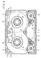
- Figure 6 is a plan view illustrating the magnetic tape cassette from below.
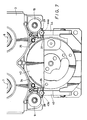
- Figure 7 is a partial plan view illustrating the head drum and the magnetic tape cassette from below when the head drum is inserted into the magnetic tape cassette.
- the embodiment of magnetic tape cassette to be described is of a very small type, and comprises a cassette casing 1 accommodating therein a magnetic tape T on and from which a pulse code modulated (PCM) signal is recorded and reproduced.
- the cassette casing 1 is formed by fastening an upper half or an upper part 2 and a lower half or a lower part 3 by screws 4, and a lid 6 is rotatably supported on the cassette casing 1 so as to open and close an opening 5 formed on the front surface sides of the upper and lower parts 2 and 3.
- the tape T is wound around a pair hubs 7 and 8 provided in correspondence with hub drive shaft insertion apertures 2a, 2b and 3a, 3b. A portion of the tape T is exposed at the opening 5 by being extended between pinch rollers 9 and 10 serving as guide rollers and pivotally supported at respective sides of the opening 5.
- a brake mechanism 11 is provided within the cassette casing 1 to brake the two hubs 7 and 8 when the tape cassette is not in use.
- Mis-erase preventing mechanisms 12 and 13 are provided on the upper and lower surface sides of the cassette casing 1 at its two rear corner portions so as to communicate with the upper and lower parts 2 and 3.
- Positioning reference apertures 14, 15 and 16, 17 are respectively formed on the cassette casing 1 at its front and back positions in the front to back direction and at its two rear side portions in the lateral direction.
- a plurality of predetermined detection holes 18 and 19 are formed on the cassette casing 1 at its rear edge portion in the lateral direction.
- Grip portions 20 and 21 are formed on the rear portions of two side walls of the cassette casing 1.
- a changer engaging portion 23 is formed along a guide groove 22 extending along the width direction of the lid 6.
- the tape T accommodated within the cassette casing 1 is recorded and/or reproduced by a rotary head using a helical scan system.
- a rotary head 41 is rotated at a predetermined slant angle relative to a head drum 42, and the head drum 42 is partly inserted into the opening 5 which is opened by rotating the lid 6 in the upper or lower direction.
- the tape T extended across the opening 5 is slidably moved so as to be wound around the insertion side peripheral surface of the head drum 42.
- a pair of tape guide members 24 and 25 whose guide portions are inclined in opposite directions are disposed in the insertion portion of the opening 5 for the head drum 42 at the positions inside the pinch rollers 9 and 10, such that they can be oscillated and moved in the lateral direction in an opposing fashion.
- the tape guide members 24 and 25 come into contact with the peripheral surface of the head drum 42, and guide the tape T so that is sandwiched between them and the peripheral surface of the head drum 42.
- the head drum 42 has at respective side portions, wing guides 43 and 44 which are inserted into the spaces between the pinch rollers 9 and 10 and the tape guide members 24 and 25 at each side of the opening 5.
- Rollers 43a and 44a are mounted on the front end portions of the two wing guides 43 and 44 respectively, and are brought into slidable contact with the tape T, urging the tape T against the tape guide members 24 and 25.
- both the wing guides 43 and 44 are inserted into the opening 5 of the cassette casing 1 such that they are positioned in the spaces between supporting elements 26 and 27 provided near the inside of the opening 5, and tape projection preventing guide protrusions 28 and 29 positioned between the supporting elements 26 and 27 and the pinch rollers 9 and 10.
- mis-erase preventing mechanisms 12 and 13 disposed in the cassette casing 1 will be described in detail with reference to Figures 1 to 3. Since the two mis-erase preventing mechanisms 12 an 13 are constructed the same, one mis-erase preventing mechanism 13 is not shown in Figures 1 to 3.
- a mis-erase preventing detection sliding member (hereinafter simply referred to as a protective plug) 31 is slidably inserted into an insertion aperture 32 which is formed through the cassette casing 1 at its rear side portion in the thickness direction of the cassette casing 1.
- the protective plug 31 is moulded of synthetic resin or the like which can be resiliently deformed.
- the length of the protective plug 31 is shorter than that of the insertion aperture 32.
- An intermediate portion 31a thereof is formed to have a cross-section which is substantially quadrilateral.
- Two end portions 31b and 31c thereof are formed to have circular cross-sections.
- the intermediate portion 31a has formed on it surfaces 34a1 and 34a2 opposing in one direction stop convex surfaces 34a and 34b placed at the central portions in an opposing relation.
- the intermediate portion 31a has formed on the other opposing surfaces 31a3 and 31a4, click stop protrusions 35a and 35b of substantially hemispherical configuration.
- the click stop protrusions 35a and 35b are displaced at a predetermined spacing from each other relative to the length direction of the protective plug 31 such that, even when the protective plug 31 is inverted, the click stop protrusions 35a and 35b can be located at the same positions.
- Protrusion surfaces 35a1 and 35b1 of the click stop protrusions 35a and 35b are thin, so that they can be slightly resiliently deformed. That is, the protrusion surfaces 35a1 and 35b1 are formed thin by forming spot facing holes 35a2 and 35b2 having predetermined depths from the surfaces facing the protrusion surfaces of the click stop protrusions 35a and 35b.
- the insertion aperture 32 into which the protective plug 31 is inserted is a hollow portion having an inner diameter nearly equal to the diameter of the transverse cross-section of the intermediate portion 31a of the protective plug 31.
- the insertion aperture 32 is formed through the upper part 2 to the lower part 3, and opposing stop concave surfaces 36a and 36b are formed on inner wall surfaces 32a and 32b of the insertion aperture 32 opposing the stop convex surfaces 34a and 34b of the plug 31 across the jointed portion of the upper and lower parts 2 and 3 of the casing 1 such that the stop convex surfaces 34a and 34b are slidably engaged therewith in the longitudinal direction of the insertion aperture 32.
- the stop convex surfaces 34a and 34b are moved and engaged with the stop concave portions 36a and 36b, whereby the stroke of the protective plug 31 is restricted.
- Click stop concave portions 37a and 37b are formed on the inner wall surfaces of the insertion aperture 32 opposing each other, that is on its surfaces 32c and 32d opposing the click stop protrusions 35a and 35b of the protective plug 31 across the joined portion of the upper and lower parts 2 and 3 of the cassette casing 1, such that the click stop concave portions 37a and 37b may be engaged with the click stop protrusions 35a and 35b.
- a guide groove 37a1 extending to the upper part 2 side is formed to be continuously communicated with the click stop concave portion 37a corresponding to one click stop protrusion 35a.
- a guide groove 37b1 extending to the lower part 3 side is formed to be continuously communicated with the click stop concave portion 37b corresponding to the other click stop protrusion 35b.
- the two guide grooves 37a1 and 37b1 are shallower than the click stop concave portions 37a and 37b, respectively.
- the stop convex surfaces 34a and 34b of the protective plug 31 are respectively positioned in the stop concave portions 36a and 36b of the insertion apertures 32 at the upper part 2 side, as shown by the solid lines in Figures 2 and 3, and under this condition, the click stop protrusion member 35b is in engagement with the click stop concave portion 37b.
- click stop protrusion members 35a and 35b are positionally displaced from each other, one click stop protrusion 35a is not engaged with one click stop concave surfaces 37a and is urged against the guide groove 37a1 continued to the upper part 2 side.
- the click stop protrusion 35a is pushed by an appropriate predetermined pushing force because the guide groove 37a1 urged therewith has the level difference between it and the inner wall surface of the insertion aperture 32 and the protrusion portion surface 35a1 is resiliently deformed.
- the other click stop protrusion 35b is urged against and engaged with the other click stop concave portion 37b, so that the protective plug 31 is positively positioned and held at the upper side of the insertion aperture 32.
- one click stop protrusion 35a is similarly urged against and engaged with one click stop concave portion 37a by an appropriate pushing force of the other click stop protrusion 35b, whereby the protective plug 31 is positively placed at the lower side of the insertion aperture 32.
- the position switching operation of the protective plug 31 since the protective plug 31 is moved under the condition that the click stop protrusions 35a and 35b are brought into slidable contact with the inner surfaces of the guide grooves 37a1 and 37b1 continued to the click stop concave portions 37a and 37b, the position of the protective plug 31 can be switched stably and smoothly.
- the click stop protrusions 35a and 35b are flexibly deformed in the direction in which they are pushed, the protective plug 31 can be moved more smoothly, and the click stop protrusions 35a and 35b can be engaged with the click stop concave portions 37a and 37b more positively.
- the position of the protective plug 31 is changed relative to the insertion aperture 32 of the cassette casing 1, and this change of the position is detected by a detecting switch through a detecting pin or the like, whereby the two conditions of the erase possible condition and the mis-erase preventing condition can be identified positively.
- the mid-erase preventing mechanisms 12 and 13 of this embodiment can perform exactly the same position switching operation, that is, detecting operation as described above even when they are inverted in their up to down direction.
- the shape of the transversal section of the protective plug 31 and the inner shape of the insertion aperture 32 are not limited to quadrilaterals and may be hexagonal or the like, in which the stop means can be formed of at least two opposing surfaces and the click stop means can be formed of other two opposing surfaces.
- the switching operation of the protective plug can be stably and smoothly carried out, whereby the magnetic tape cassette can be positively placed in the erase possible condition and the mis-erase preventing condition with ease.
- the protective plug when the protective plug is pushed by a larger pushing force that is necessary in this switching operation, or when the click stop means is worn, the protective plug can be prevented from being disengaged from the inserted aperture and mis-erasure can be positively avoided, so the magnetic tape cassette is reliable.
Landscapes
- Packaging Of Annular Or Rod-Shaped Articles, Wearing Apparel, Cassettes, Or The Like (AREA)
Applications Claiming Priority (2)
| Application Number | Priority Date | Filing Date | Title |
|---|---|---|---|
| JP1317029A JP2730228B2 (ja) | 1989-12-06 | 1989-12-06 | テープカセット |
| JP317029/89 | 1989-12-06 |
Publications (3)
| Publication Number | Publication Date |
|---|---|
| EP0431913A2 true EP0431913A2 (fr) | 1991-06-12 |
| EP0431913A3 EP0431913A3 (en) | 1992-04-15 |
| EP0431913B1 EP0431913B1 (fr) | 1995-11-08 |
Family
ID=18083631
Family Applications (1)
| Application Number | Title | Priority Date | Filing Date |
|---|---|---|---|
| EP90313189A Expired - Lifetime EP0431913B1 (fr) | 1989-12-06 | 1990-12-05 | Cassettes à bande magnétique |
Country Status (4)
| Country | Link |
|---|---|
| US (1) | US5206781A (fr) |
| EP (1) | EP0431913B1 (fr) |
| JP (1) | JP2730228B2 (fr) |
| KR (1) | KR100248928B1 (fr) |
Families Citing this family (3)
| Publication number | Priority date | Publication date | Assignee | Title |
|---|---|---|---|---|
| US5335875A (en) * | 1992-12-10 | 1994-08-09 | Matsushita Electric Industrial Co., Ltd. | Tape cassette structure |
| US5772143A (en) * | 1996-02-12 | 1998-06-30 | Imation Corp. | Guides for magnetic tape and method of making the same |
| USD835033S1 (en) * | 2015-08-18 | 2018-12-04 | Yeoshua Sorias | Magnetic charger plug |
Family Cites Families (17)
| Publication number | Priority date | Publication date | Assignee | Title |
|---|---|---|---|---|
| US3686470A (en) * | 1970-11-27 | 1972-08-22 | Ibm | Two shell magnetic tape cartridge |
| DE2912423A1 (de) * | 1979-03-29 | 1980-10-09 | Basf Ag | Magnetbandkassette und geraet dafuer |
| US4412260A (en) * | 1981-04-24 | 1983-10-25 | Magnetic Peripherals Inc. | Cartridge receiver mechanism |
| JPS6319976Y2 (fr) * | 1981-06-04 | 1988-06-03 | ||
| JPS5860475A (ja) * | 1981-10-07 | 1983-04-09 | Sony Corp | テ−プカセツト |
| JPS6047186U (ja) * | 1983-09-09 | 1985-04-03 | ティーディーケイ株式会社 | 磁気テ−プカ−トリツジ |
| JPS6129472A (ja) * | 1984-07-21 | 1986-02-10 | Sony Corp | 磁気テ−プカセツト |
| JPS6132285A (ja) * | 1984-07-23 | 1986-02-14 | Sony Corp | 磁気テ−プカセツト |
| JPS6133290U (ja) * | 1984-07-28 | 1986-02-28 | ソニー株式会社 | 記録媒体収容カセツト |
| JPS61105983U (fr) * | 1984-12-17 | 1986-07-05 | ||
| US4844377A (en) * | 1986-07-18 | 1989-07-04 | Matsushita Electric Industrial Co., Ltd. | Tape cassette |
| US4791504A (en) * | 1986-09-11 | 1988-12-13 | Sony Corporation | Tape cassette with lid lock and tape characteristic indicating member |
| US5184255A (en) * | 1987-01-16 | 1993-02-02 | Shape Inc. | Video tape cassette with a reusable recording enable/disable slide tab |
| JP2540883B2 (ja) * | 1987-10-14 | 1996-10-09 | ソニー株式会社 | テ―プカセットの誤消去防止装置 |
| US5087998A (en) * | 1988-01-14 | 1992-02-11 | Kengo Oishi | Magnetic tape cassette having improved erasure preventing device |
| CA1328015C (fr) * | 1988-03-11 | 1994-03-22 | Shuji Haruna | Cartouche de disque |
| JPH01294252A (ja) * | 1988-05-23 | 1989-11-28 | Hitachi Ltd | 誤消去防止用ツメ検出装置 |
-
1989
- 1989-12-06 JP JP1317029A patent/JP2730228B2/ja not_active Expired - Lifetime
-
1990
- 1990-12-04 KR KR1019900019800A patent/KR100248928B1/ko not_active Expired - Fee Related
- 1990-12-05 EP EP90313189A patent/EP0431913B1/fr not_active Expired - Lifetime
- 1990-12-05 US US07/622,779 patent/US5206781A/en not_active Expired - Fee Related
Also Published As
| Publication number | Publication date |
|---|---|
| JPH03178091A (ja) | 1991-08-02 |
| EP0431913A3 (en) | 1992-04-15 |
| KR910013210A (ko) | 1991-08-08 |
| KR100248928B1 (ko) | 2000-03-15 |
| EP0431913B1 (fr) | 1995-11-08 |
| JP2730228B2 (ja) | 1998-03-25 |
| US5206781A (en) | 1993-04-27 |
Similar Documents
| Publication | Publication Date | Title |
|---|---|---|
| CA1071607A (fr) | Cassette de bande magnetique | |
| GB2115782A (en) | Tape cassette with front cover | |
| KR880001727B1 (ko) | 자기테이프 카셋트 | |
| EP0295920B1 (fr) | Cassette à bande magnétique | |
| US4703384A (en) | Magnetic tape cassette with reel-lock mechanism | |
| KR100248933B1 (ko) | 테이프카셋트 | |
| EP0702828B1 (fr) | Cartouches de bande pour enregristrement magnetique, presentant le meme format mais mecaniquement incompatibles | |
| EP0266794B1 (fr) | Dispositif de fermeture par coulissement pour cassette à disque | |
| EP0431913B1 (fr) | Cassettes à bande magnétique | |
| US5504644A (en) | Recording/erasing prevention device | |
| EP0431898B1 (fr) | Cassettes à bande magnétique | |
| EP0450976B1 (fr) | Cassette à bande | |
| US4743992A (en) | Magnetic tape cassette | |
| EP0431914B1 (fr) | Cassettes à bande magnétique | |
| US5255144A (en) | Brake device for tape reel in magnetic tape cassette | |
| US4802049A (en) | Disc cartridge | |
| US5689393A (en) | Magnetic disk cartridge having an opening for a magnetic head on a side thereof | |
| KR970003700Y1 (ko) | 카세트 테이프 인출장치 | |
| US4311286A (en) | Fixed reel type endless tape cassette | |
| US6286776B1 (en) | Magnetic tape cassette | |
| CA1133126A (fr) | Cassette de bande sans fin a bobine fixe | |
| JP2976540B2 (ja) | テープカセット | |
| JP3239389B2 (ja) | テープカセット | |
| JP3082366B2 (ja) | テープカセット | |
| US5868337A (en) | Large tape cassette usable in a recording/reproducing apparatus capable of using both a large tape cassette and a miniature tape cassette |
Legal Events
| Date | Code | Title | Description |
|---|---|---|---|
| PUAI | Public reference made under article 153(3) epc to a published international application that has entered the european phase |
Free format text: ORIGINAL CODE: 0009012 |
|
| AK | Designated contracting states |
Kind code of ref document: A2 Designated state(s): FR GB IT |
|
| PUAL | Search report despatched |
Free format text: ORIGINAL CODE: 0009013 |
|
| AK | Designated contracting states |
Kind code of ref document: A3 Designated state(s): FR GB IT |
|
| 17P | Request for examination filed |
Effective date: 19920821 |
|
| 17Q | First examination report despatched |
Effective date: 19940509 |
|
| GRAA | (expected) grant |
Free format text: ORIGINAL CODE: 0009210 |
|
| AK | Designated contracting states |
Kind code of ref document: B1 Designated state(s): FR GB IT |
|
| ITF | It: translation for a ep patent filed | ||
| ET | Fr: translation filed | ||
| PLBE | No opposition filed within time limit |
Free format text: ORIGINAL CODE: 0009261 |
|
| STAA | Information on the status of an ep patent application or granted ep patent |
Free format text: STATUS: NO OPPOSITION FILED WITHIN TIME LIMIT |
|
| 26N | No opposition filed | ||
| PGFP | Annual fee paid to national office [announced via postgrant information from national office to epo] |
Ref country code: GB Payment date: 20011205 Year of fee payment: 12 |
|
| PGFP | Annual fee paid to national office [announced via postgrant information from national office to epo] |
Ref country code: FR Payment date: 20011212 Year of fee payment: 12 |
|
| REG | Reference to a national code |
Ref country code: GB Ref legal event code: IF02 |
|
| PG25 | Lapsed in a contracting state [announced via postgrant information from national office to epo] |
Ref country code: GB Free format text: LAPSE BECAUSE OF NON-PAYMENT OF DUE FEES Effective date: 20021205 |
|
| GBPC | Gb: european patent ceased through non-payment of renewal fee | ||
| PG25 | Lapsed in a contracting state [announced via postgrant information from national office to epo] |
Ref country code: FR Free format text: LAPSE BECAUSE OF NON-PAYMENT OF DUE FEES Effective date: 20030901 |
|
| REG | Reference to a national code |
Ref country code: FR Ref legal event code: ST |
|
| PG25 | Lapsed in a contracting state [announced via postgrant information from national office to epo] |
Ref country code: IT Free format text: LAPSE BECAUSE OF NON-PAYMENT OF DUE FEES;WARNING: LAPSES OF ITALIAN PATENTS WITH EFFECTIVE DATE BEFORE 2007 MAY HAVE OCCURRED AT ANY TIME BEFORE 2007. THE CORRECT EFFECTIVE DATE MAY BE DIFFERENT FROM THE ONE RECORDED. Effective date: 20051205 |