EP0432082B1 - Druckempfindliches Ventil - Google Patents
Druckempfindliches Ventil Download PDFInfo
- Publication number
- EP0432082B1 EP0432082B1 EP19900610073 EP90610073A EP0432082B1 EP 0432082 B1 EP0432082 B1 EP 0432082B1 EP 19900610073 EP19900610073 EP 19900610073 EP 90610073 A EP90610073 A EP 90610073A EP 0432082 B1 EP0432082 B1 EP 0432082B1
- Authority
- EP
- European Patent Office
- Prior art keywords
- valve
- spring
- seat
- nozzle
- flow path
- Prior art date
- Legal status (The legal status is an assumption and is not a legal conclusion. Google has not performed a legal analysis and makes no representation as to the accuracy of the status listed.)
- Expired - Lifetime
Links
- 239000012530 fluid Substances 0.000 claims description 7
- 230000008878 coupling Effects 0.000 claims 2
- 238000010168 coupling process Methods 0.000 claims 2
- 238000005859 coupling reaction Methods 0.000 claims 2
- 230000002093 peripheral effect Effects 0.000 description 3
- 230000001105 regulatory effect Effects 0.000 description 3
- 230000003247 decreasing effect Effects 0.000 description 2
- 230000009969 flowable effect Effects 0.000 description 2
- 239000007788 liquid Substances 0.000 description 2
- 239000000853 adhesive Substances 0.000 description 1
- 230000001070 adhesive effect Effects 0.000 description 1
- 230000001276 controlling effect Effects 0.000 description 1
- 239000000463 material Substances 0.000 description 1
- 239000011236 particulate material Substances 0.000 description 1
- 239000007787 solid Substances 0.000 description 1
- 230000008719 thickening Effects 0.000 description 1
Images

Classifications
-
- B—PERFORMING OPERATIONS; TRANSPORTING
- B05—SPRAYING OR ATOMISING IN GENERAL; APPLYING FLUENT MATERIALS TO SURFACES, IN GENERAL
- B05B—SPRAYING APPARATUS; ATOMISING APPARATUS; NOZZLES
- B05B1/00—Nozzles, spray heads or other outlets, with or without auxiliary devices such as valves, heating means
- B05B1/30—Nozzles, spray heads or other outlets, with or without auxiliary devices such as valves, heating means designed to control volume of flow, e.g. with adjustable passages
- B05B1/32—Nozzles, spray heads or other outlets, with or without auxiliary devices such as valves, heating means designed to control volume of flow, e.g. with adjustable passages in which a valve member forms part of the outlet opening
- B05B1/323—Nozzles, spray heads or other outlets, with or without auxiliary devices such as valves, heating means designed to control volume of flow, e.g. with adjustable passages in which a valve member forms part of the outlet opening the valve member being actuated by the pressure of the fluid to be sprayed
Definitions
- the present invention relates to a valve of the kind, having a cylindrical valve housing with a rectlinear continuous flow path, a conical valve seat disposed on the valve housing concentric to the flow path and a disc-shaped valve body with at least a stem and a closure member.
- the valve body is arranged fluid tight and moveable in the valve housing and actuated by a spring device, which further end makes contact to a spring seat.
- the valve according to the invention may be employed for controlling the flow of a liquid or gaseous medium from a container or in a pipe, wherein the medium is contained.
- Valves for this service are usually globe valves with a valve body fastened to a stem, which stem being actuated by the force of an actuator spring arranged externally to the valve housing.
- the valve closure member of such a valve is lifted from the valve seat when the pressure in the medium to be controlled extends a predetermined limit where the spring force is defeated, which otherwise forces the closure member against the seat.
- the medium flow through the known globe valves is caused to take a non-linear path through the seat and along the closure member, which results in a large pressure drop.
- a valve with a linear flow path is the known gate valve. This valve is opened when the gate is moved by the stem into the yoke or top section of the valve.
- the yoke or top section is positioned externally to the valve housing. Neither this kind of valve provides a compact valve assembly, having all components arranged within the valve housing.
- a compact seat valve with a substantially rectilinear continuous flow path is mentioned in DK-Patent Publication No. 4345/75, wherein a circular valve seat is arranged within the valve housing concentric to the flow path.
- a valve ball which works together with the seat is spring loaded by a spiral spring.
- One end of the spring makes contact to a spring seat provided with a central bore.
- the opposite end of the spring which actuates the valve ball, makes contact to a further spring seat having in its circumference grooves parallel to the axis of the spring seat.
- the flow path is thereby obtained through the grooves and the central bore of the spring seat.
- the valve is suitable as a check valve for a suction flask.
- a disadvantage of the mentioned valve is the restricted path through the grooves of the spring seat and the arrangement of the spring within the flow path. This is particular disadvantageous, when the valve is used to control flow of highly viscous media or flowable solids.
- a closure valve with a rectilinear flow path and an annular pressure sensitive plunger is mentioned in US Patent No. 2,109,397.
- the disclosed valve is intended for dispensing contents from collapsible tubes or similar containers, wherein contents passing through the neck portion of a tube exert a downward pressure on the plunger to unseat the valve upon squeezing the tube. When squeezing of the tube is stopped a spring returns the valve to seated position.
- the object of the present invention is to provide a valve of that kind, which has a rectilinear continuous flow path through the valve housing, and which is useful to control a stream of highly viscous or flowable media without the disadvantages of the known valves.
- the present invention comprises a valve of the introductory mentioned kind, and wherein the stem is coaxially to the axis of the flow path arranged on the valve body, which concentric to the axis of the flow path is provided with a central bore and with an axially directed cylindrical nozzle opposite to the stem, the nozzle surrounds concentric and moveable in fluid tight manner a cylindrical nozzle guide arranged on the spring seat around an inlet section, the inlet section is in form of a central bore through the spring seat and has a cross sectional area, which is less than the cross sectional area of the valve body, the spring device is concentrically arranged around the axially directed nozzle.
- the valve is characterized in that the valve closure member is provided with an auxiliary check valve.
- the check valve is of the kind comprising a plug with peripheral grooves parallel to the axis of the plug, thereby providing a flow path from the inside of the main valve housing to the outside of the valve.
- the plug is disposed in a bore through the closure member and has on the side being outside the main valve housing a bonnet or a thickening, which prevents the plug from sliding through the bore.
- the plug On the side being inside the housing, the plug is provided with a cone or disc-shaped body, which upon pressure in the main valve is forced tightly against the closure member.
- the flow path through the valve according to the invention is thus provided by the central bore through the spring seat, the central bore through the valve body together with the axially directed nozzle, and by the conical seat, which concentric to the axis of the flow path is arranged on the valve housing.
- the spring device is thereby disposed outside the flow path, which is advantageous, in particular when the valve is flushed by viscous liquids or particulate materials.
- the pressure is equalized by leaking air or a medium outside the valve through the grooves in the plug and into the space defined by the main valve body and valve seat.
- a particular feature of the valve according to the invention is the difference between the cross sectional areas of the inlet section and the disc-shaped valve body, which is exposed to the pressure in the medium controlled by the valve.
- the pressure exerted by a fluid in closed containers is as known the same all over the boundaries of a container.
- valve disc By providing the valve disc with a larger area than the area of the inlet section a large spring force exerted by the spring device can act on the closure member in order to provide an air tight closure of the valve, which is particular advantageously, when the medium to be controlled comprises air sensible or air hardening components, such as pastes or adhesives.
- the pressure in the medium can be relatively low in order to open the valve, which is further desirable, when the medium is released from a container by manual pressure on the container.
- the distance between the valve body and the spring seat can be regulated continuously by arranging the spring seat displaceable in the valve housing.
- the spring seat is thereby formed as a cylinder with projections on the cylinder wall, preferably a thread, which acts together with a compatible projection on the inner wall of the valve housing.
- valve according to the invention may further advantageously be used as exit nozzle in extruders.
- valve seat may be provided with e.g. a cylindrical nozzle piece.
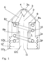
- valve comprises a cylindrical valve housing 1, which in its upper part is provided with a cone-shaped valve seat 3.
- Valve seat 3 has a circular opening 3a concentric to the axis of flow path 2 through the valve. Opening 3a constitutes the outlet of the valve.
- a valve closure member 4, which acts together with valve seat 3, has in the shown embodiment a conical shape. Other shapes, such as a hemispherical or a lentoide shape, may be suitable as well.
- Closure member 4 may as mentioned above be provided with an inlet valve 40 (FIG. 2). As shown in FIG. 2 and FIG. 3 the closure member 4 has in such an embodiment built in a cylindrical plug 41, which slides in a central bore 42 through closure member 4. Plug 41 is provided with peripheral grooves 41a parallel to the axis of the plug. A bonnet 41b on the plug 41 outside the main valve, prevents the plug from sliding completely through bore 42. On the opposite side plug 41 has a conical body 41c, which acts together with an equivalent conicity 4b on the downside of closure member 4.
- Closure member 4 (FIG. 1) is connected via a valve stem 6 to a valve body 8, which consists of a valve disc 8a and an axial directed nozzle 8b around a central bore 8c through body 8.
- valve disc 8a makes fluid tight contact to the inner wall 1a of housing 1.
- Body 8 is at its downside loaded with a spiral spring 10, which further end makes contact to a cylindrical spring seat 12.
- Spring seat 12 is in the shown embodiment formed as screw plunger with a thread 12a, which acts together with a compatibel thread 1b at the inner wall 1a of the valve housing.
- valve As mentioned hereinbefore it is possible to control in such an embodiment of the valve the flow through the valve by varying the distance between spring seat 12 and the closure member 8.
- the valve may be closed constantly, by screwing seat 12 into the valve housing 1, until seat 12 hits nozzle 8b, so that any movement of body 8 is prevented.
- Spring seat 12 is further provided with a central bore 12c, and an axial disposed guide nozzle 12b, which is surrounded tightly slidding ny nozzle 8b.
- Central bore 12c constitutes the valve inlet 11, through which the medium to be controlled flows into the valve flow path 2.
- Flow path 2 is further constituted by central bore 12c and 8c through spring seat 12 and valve disc 8, and by guide nozzle 12b, nozzle 8b and the conical valve seat 3 with annular opening 3a.
- valve is in its normal state closed and a medium flowing into the valve housing fills up the space between valve seat 3 and the upper side of valve body 8.
- the body 8 is moved by a force directed against the upper side of valve disc 8a, which force is proportional to the medium pressure at inlet 11 and the area of disc 8a.
- Body 8 is moved thereby towards spring seat 12 when this force overcomes the spring force of spring 10.
- the flow path through opening 3a in the valve seat is then opened and the medium flows through the valve.
- valve housing 1 may be provided with a thread allowing the valve to be screwed into a pipe or tube.
- the central bore 12c through the spring seat 12 may be provided with a thread, a coupler or a spring lock by which the valve may be fastened to a container.
Landscapes
- Lift Valve (AREA)
- Check Valves (AREA)
- Closures For Containers (AREA)
Claims (7)
- Ventil mit zylindrischem Ventilgehäuse (1) und ununterbrochenem, geradlinigen Strömungsweg (2), einem konischen Ventilsitz (3) mit kreisförmiger Ventilöffnung (3a), die konzentrisch zum Strömungsweg (2) im Ventilgehäuse (1) vorhanden ist, und einem Ventilkörper (8), welcher eine Ventilscheibe (8a) und wenigstens einen an der Ventilscheibe (8a) vorhandenen und ein Ventilschließelement (4) tragenden Arm (6) aufweist, wobei der Ventilkörper (8) flüssigkeitsdicht und bewegbar im Gehäuse (1) angeordnet ist und mittels einer Federeinrichtung (10) betätigt wird, deren anderes Ende in Kontakt mit einem Federsitz (12) steht, der Arm (6) axial zum Strömungsweg (2) versetzt am Ventilkörper (8) vorhanden ist, welcher eine Zentralbohrung (8c) und an der dem Arm (6) gegenüberliegenden Seite und konzentrisch zur Zentralbohrung (8c) eine axial verlaufende, zylindrische Düse (8b) aufweist, die konzentrisch und bewegbar sowie flüssigkeitsdicht eine zylindrische Düsenführung (12b) umgibt, die am Federsitz (12) vorhanden ist und konzentrisch zu einem Einlaßabschnitt (11) liegt, welcher durch eine Zentralbohrung im Federsitz (12) gebildet ist und eine Querschnittsfläche aufweist, die kleiner ist als die Querschnittsfläche der Ventilscheibe (8a), und wobei die Federeinrichtung (10) die axial verlaufende Düse (8b, 12b) konzentrisch umgibt, dadurch gekennzeichnet, daß das Ventilschließelement (4) mit einem Hilfsprüfventil (40) ausgestattet ist, das einen zylindrischen Bolzen (41) aufweist, der in seiner Umfangsrichtung gesehen achsparallele Furchen (41a) besitzt.
- Ventil nach Anspruch 1, dadurch gekennzeichnet, daß der Federsitz (12) in seiner Umfangsrichtung mit einem Vorsprung (12a) versehen ist, der mit einem äquivalenten Vorsprung (1b) an der Inneren Wand (1a) des Ventilgehäuses zusammenarbeitet.
- Ventil nach Anspruch 2, dadurch gekennzeichnet, daß der Vorsprung (12a, 1b) als Gewindestück ausgebildet ist.
- Ventil nach Anspruch 2, dadurch gekennzeichnet, daß der Vorsprung (12a, 1b) als Federschloß ausgebildet ist.
- Ventil nach Anspruch 1, dadurch gekennzeichnet, daß der Einlaßabschnitt (11) mit einer Kupplungseinrichtung ausgestattet ist.
- Ventil nach Anspruch 5, dadurch gekennzeichnet, daß die Kupplungseinrichtung in Form eines Gewindestücks vorliegt.
- Verwendung eines Ventils nach irgendeinem der vorhergehenden Ansprüche als Ausgangsdüse einer Extrudiereinrichtung.
Applications Claiming Priority (2)
| Application Number | Priority Date | Filing Date | Title |
|---|---|---|---|
| DK6172/89 | 1989-12-07 | ||
| DK617289A DK162857C (da) | 1989-12-07 | 1989-12-07 | Trykfoelsom ventil, samt anvendelse af denne |
Publications (2)
| Publication Number | Publication Date |
|---|---|
| EP0432082A1 EP0432082A1 (de) | 1991-06-12 |
| EP0432082B1 true EP0432082B1 (de) | 1994-11-02 |
Family
ID=8147821
Family Applications (1)
| Application Number | Title | Priority Date | Filing Date |
|---|---|---|---|
| EP19900610073 Expired - Lifetime EP0432082B1 (de) | 1989-12-07 | 1990-12-06 | Druckempfindliches Ventil |
Country Status (3)
| Country | Link |
|---|---|
| EP (1) | EP0432082B1 (de) |
| DE (1) | DE69013863T2 (de) |
| DK (1) | DK162857C (de) |
Families Citing this family (4)
| Publication number | Priority date | Publication date | Assignee | Title |
|---|---|---|---|---|
| DE4117999A1 (de) * | 1991-06-01 | 1992-12-03 | Erno Raumfahrttechnik Gmbh | Vorrichtung zur steuerung eines fluessigkeitsstromes |
| FR2702664B1 (fr) * | 1992-09-24 | 1995-09-01 | Cerberus Guinard | Dispositif d'extinction d'incendie dans une enceinte à buse d'insufflation d'un fluide. |
| FR2695832B1 (fr) * | 1992-09-24 | 1994-11-18 | Cerberus Guinard | Dispositif d'extinction d'incendie dans une enceinte à buse d'insufflation d'un fluide. |
| JP6887288B2 (ja) * | 2017-03-30 | 2021-06-16 | 株式会社ミマキエンジニアリング | 印刷装置 |
Family Cites Families (3)
| Publication number | Priority date | Publication date | Assignee | Title |
|---|---|---|---|---|
| US2109397A (en) * | 1935-06-13 | 1938-02-22 | Henderson Douglas | Closure for collapsible tubes and containers |
| FR825740A (fr) * | 1936-08-18 | 1938-03-11 | Dispositif de fermeture automatique d'une capacité tubulaire déformable contenant une masse fluide | |
| DE2703095A1 (de) * | 1977-01-24 | 1978-07-27 | Iliades Charalambos | Tubenverschlussautomatik |
-
1989
- 1989-12-07 DK DK617289A patent/DK162857C/da not_active IP Right Cessation
-
1990
- 1990-12-06 EP EP19900610073 patent/EP0432082B1/de not_active Expired - Lifetime
- 1990-12-06 DE DE1990613863 patent/DE69013863T2/de not_active Expired - Fee Related
Also Published As
| Publication number | Publication date |
|---|---|
| DK162857B (da) | 1991-12-16 |
| DK617289D0 (da) | 1989-12-07 |
| DE69013863D1 (de) | 1994-12-08 |
| DK162857C (da) | 1992-05-04 |
| DE69013863T2 (de) | 1995-05-18 |
| DK617289A (da) | 1991-06-08 |
| EP0432082A1 (de) | 1991-06-12 |
Similar Documents
| Publication | Publication Date | Title |
|---|---|---|
| US5197708A (en) | Tubing pinch valve device | |
| US5301852A (en) | Manually operated pump for dispensing liquid or creamy substances at a predetermined constant pressure | |
| US4562852A (en) | Safety valve | |
| JPH01124561A (ja) | 計量機能を備えた容器閉鎖キャップ | |
| EP1121323B1 (de) | Abgabevorrichtung in form eines deckels | |
| JPS6149549B2 (de) | ||
| US5573037A (en) | Faucet valve with external cam and pinch tubes | |
| US6123101A (en) | Spring body excess flow valve | |
| US2869764A (en) | Self-closing valve construction for a pressurized container | |
| US4468001A (en) | Shut off valve for fluids | |
| US5083749A (en) | Plastic needle valve | |
| EP0432082B1 (de) | Druckempfindliches Ventil | |
| US2889086A (en) | Dispensing valve with stem sealing means | |
| DK144744B (da) | Ventil med en spindeltaetning | |
| US3730398A (en) | Liquid dispensing apparatus | |
| JPH01503728A (ja) | 流体のためのシャットオフ・バルブ | |
| US2769582A (en) | Closure mechanism for containers | |
| JPH05246474A (ja) | 噴霧容器用の作動部品 | |
| US4479507A (en) | Fluid pressure operated valve | |
| US6135134A (en) | Excess flow volume control valve | |
| US6874521B1 (en) | High to low gas flow regulator | |
| US6095379A (en) | Tap for bottles | |
| US3757814A (en) | Liquid control and dispensing | |
| US5079992A (en) | Longitudinally controllable adjustment device | |
| US2786645A (en) | Line seating conical valves |
Legal Events
| Date | Code | Title | Description |
|---|---|---|---|
| PUAI | Public reference made under article 153(3) epc to a published international application that has entered the european phase |
Free format text: ORIGINAL CODE: 0009012 |
|
| AK | Designated contracting states |
Kind code of ref document: A1 Designated state(s): DE FR GB IT NL SE |
|
| 17P | Request for examination filed |
Effective date: 19911205 |
|
| 17Q | First examination report despatched |
Effective date: 19930316 |
|
| GRAA | (expected) grant |
Free format text: ORIGINAL CODE: 0009210 |
|
| AK | Designated contracting states |
Kind code of ref document: B1 Designated state(s): DE FR GB IT NL SE |
|
| PG25 | Lapsed in a contracting state [announced via postgrant information from national office to epo] |
Ref country code: IT Free format text: LAPSE BECAUSE OF FAILURE TO SUBMIT A TRANSLATION OF THE DESCRIPTION OR TO PAY THE FEE WITHIN THE PRESCRIBED TIME-LIMIT;WARNING: LAPSES OF ITALIAN PATENTS WITH EFFECTIVE DATE BEFORE 2007 MAY HAVE OCCURRED AT ANY TIME BEFORE 2007. THE CORRECT EFFECTIVE DATE MAY BE DIFFERENT FROM THE ONE RECORDED. Effective date: 19941102 Ref country code: FR Effective date: 19941102 Ref country code: NL Effective date: 19941102 |
|
| REF | Corresponds to: |
Ref document number: 69013863 Country of ref document: DE Date of ref document: 19941208 |
|
| EN | Fr: translation not filed | ||
| NLV1 | Nl: lapsed or annulled due to failure to fulfill the requirements of art. 29p and 29m of the patents act | ||
| PLBE | No opposition filed within time limit |
Free format text: ORIGINAL CODE: 0009261 |
|
| STAA | Information on the status of an ep patent application or granted ep patent |
Free format text: STATUS: NO OPPOSITION FILED WITHIN TIME LIMIT |
|
| 26N | No opposition filed | ||
| PGFP | Annual fee paid to national office [announced via postgrant information from national office to epo] |
Ref country code: GB Payment date: 19971204 Year of fee payment: 8 |
|
| PGFP | Annual fee paid to national office [announced via postgrant information from national office to epo] |
Ref country code: SE Payment date: 19971215 Year of fee payment: 8 |
|
| PGFP | Annual fee paid to national office [announced via postgrant information from national office to epo] |
Ref country code: DE Payment date: 19971218 Year of fee payment: 8 |
|
| PG25 | Lapsed in a contracting state [announced via postgrant information from national office to epo] |
Ref country code: GB Free format text: LAPSE BECAUSE OF NON-PAYMENT OF DUE FEES Effective date: 19981206 |
|
| PG25 | Lapsed in a contracting state [announced via postgrant information from national office to epo] |
Ref country code: SE Free format text: LAPSE BECAUSE OF NON-PAYMENT OF DUE FEES Effective date: 19981207 |
|
| GBPC | Gb: european patent ceased through non-payment of renewal fee |
Effective date: 19981206 |
|
| PG25 | Lapsed in a contracting state [announced via postgrant information from national office to epo] |
Ref country code: DE Free format text: LAPSE BECAUSE OF NON-PAYMENT OF DUE FEES Effective date: 19991001 |