EP0432097A1 - Machine à étiqueter - Google Patents
Machine à étiqueter Download PDFInfo
- Publication number
- EP0432097A1 EP0432097A1 EP90810927A EP90810927A EP0432097A1 EP 0432097 A1 EP0432097 A1 EP 0432097A1 EP 90810927 A EP90810927 A EP 90810927A EP 90810927 A EP90810927 A EP 90810927A EP 0432097 A1 EP0432097 A1 EP 0432097A1
- Authority
- EP
- European Patent Office
- Prior art keywords
- motor
- stepping motor
- feed roller
- labeling machine
- machine according
- Prior art date
- Legal status (The legal status is an assumption and is not a legal conclusion. Google has not performed a legal analysis and makes no representation as to the accuracy of the status listed.)
- Withdrawn
Links
- 238000002372 labelling Methods 0.000 title claims abstract description 17
- 238000013016 damping Methods 0.000 claims abstract description 16
- 230000005540 biological transmission Effects 0.000 claims description 5
- 239000000853 adhesive Substances 0.000 claims description 3
- 239000002184 metal Substances 0.000 claims description 2
- 239000013013 elastic material Substances 0.000 claims 1
- 238000000034 method Methods 0.000 abstract 1
- 230000010355 oscillation Effects 0.000 abstract 1
- 230000008878 coupling Effects 0.000 description 4
- 238000010168 coupling process Methods 0.000 description 4
- 238000005859 coupling reaction Methods 0.000 description 4
- 229910000831 Steel Inorganic materials 0.000 description 1
- 230000001419 dependent effect Effects 0.000 description 1
- 238000010586 diagram Methods 0.000 description 1
- 238000006073 displacement reaction Methods 0.000 description 1
- 230000008030 elimination Effects 0.000 description 1
- 238000003379 elimination reaction Methods 0.000 description 1
- 230000002349 favourable effect Effects 0.000 description 1
- 239000010959 steel Substances 0.000 description 1
- 238000011144 upstream manufacturing Methods 0.000 description 1
- 238000003466 welding Methods 0.000 description 1
Images

Classifications
-
- B—PERFORMING OPERATIONS; TRANSPORTING
- B65—CONVEYING; PACKING; STORING; HANDLING THIN OR FILAMENTARY MATERIAL
- B65C—LABELLING OR TAGGING MACHINES, APPARATUS, OR PROCESSES
- B65C11/00—Manually-controlled or manually-operable label dispensers, e.g. modified for the application of labels to articles
- B65C11/006—Manually-controlled or manually-operable label dispensers, e.g. modified for the application of labels to articles using electrical or electro-mechanical means
Definitions
- the present invention relates to a labeling machine according to the preamble of the independent claim.
- a difficulty that arises in this connection arises from the fact that the armature of the stepping motor used to drive the feed roller starts to vibrate with every switching step.
- the motor torque was therefore forced to be indirect, i.e. mostly through a toothed belt drive to transfer to the feed roller, which made the drive more expensive and also at the cost of its stability (see DE-OS 35 24 842 and 38 10 464).
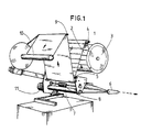
- FIG. 1 is a schematic, greatly simplified overall perspective view of an embodiment of the labeling machine according to the invention.
- Fig. 9 shows this variant in section
- a carrier web 1 which is provided with detachable, self-adhesive labels 2, is pulled from a dispenser 3 on a labeling machine, which is shown in a highly simplified manner with the omission of insignificant details, and fed to a dispensing edge 6 via deflection rollers 4, 5.
- the labels detach from the carrier web 1 when it is deflected, and the latter is fed to a rewinder 10 via further deflection rollers 7, 8, 9.
- the lower of the two paired deflecting rollers 7, 8 is designed as a feed roller 7, i.e. coupled to an electric motor drive 11.
- the feed roller 7 could, however, also be arranged upstream of the dispensing edge 6, it also being possible to dispense with the rewinder 10 and to drop the carrier web freed from the labels directly into a collecting container arranged below the dispensing edge.
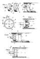
- a first drive disk 13 preferably made of metal, is wedged onto the motor shaft denoted by 12 and secured by means of grub screw 14.
- another driving disk 18 is connected in a rotationally rigid manner to the same, which also has two driving pins 19, 20 which are offset by 180 ° relative to one another.
- An elastic damping element 21 is now arranged between the two drive plates 13 and 18, in whose four through holes 22 the pins 14, 15 protrude from the motor side, and the pins 19, 20 protrude from the feed roller side.
- the torque of the drive motor is transmitted to the feed roller in spite of the vibrations occurring on the armature of the stepping motor and despite the direct, coaxial coupling of the motor and feed roller, so that there are none on the feeder roller even in the critical frequency range of the motor Resonance phenomena are more noticeable.
- the structural design of the exemplary embodiment shown can be modified by a person skilled in the art, for example, in such a way that the driving disk is not fixed in a torsionally rigid manner to the inner wall of the feed roller, but is rigidly coupled to the feed roller axis 17, in which case, however, the axis 17 would then have to be coupled in a torsionally rigid manner.
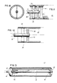
- FIGS. 5 to 7 it is possible, according to FIGS. 5 to 7, to arrange a set-back end wall 24 within the feed roller 23, the end wall 24 being offset by two by 180 ° offset driver pin 25, 26 is provided and takes over the function of the driver disk designated 18 in FIG. 2.
- an elastic damping element 31 with four through holes 32 is arranged between a driving disk 28, which is seated on the motor shaft 27 and has two driving pins 29 and 30, and said end wall 24.
- the elastic damping member 21 (Fig. 2) or 31 (Fig. 5) is preferably made of rubber or an elastic plastic.
- a drive plate 34 is attached to the motor shaft end 33; an elastic damping member 37 is arranged between this and a driving disk 36 anchored in the preferred roller 35 in a rotationally rigid manner and glued to the two disks 36 and 37, vulcanized onto the same or otherwise firmly connected to the same.
- FIGS. 10 to 12 shows a leaf spring 38, preferably made of steel, the ends of which engage in grooves 39 of the preferred roller wall 40.
- the leaf spring 38 is guided through a through slot 42 made in the motor shaft 41, so that elastic damping, which prevents the occurrence of resonances, again results here.
- the desired elimination of the undesired resonances could also be achieved by using a torsion bar 43 which, on the one hand, for example by means of a rigid or elastic coupling element 44, with the motor shaft 45, and on the other hand, for example by welding 46 to an end wall 49 of the feed roller 47 , is rigidly coupled.
- a torsion bar 43 which, on the one hand, for example by means of a rigid or elastic coupling element 44, with the motor shaft 45, and on the other hand, for example by welding 46 to an end wall 49 of the feed roller 47 , is rigidly coupled.
- the torque of the motor shaft 45 which is loosely rotatable through the motor-side end wall 48 of the feed roller, is damped in such a way that the feed roller is protected from the vibrations of the stepping motor.
- the desired damping function could also be achieved by a pneumatic damping element.
- stepper motors that are directly driven in the manner described above have very steep start-up and braking ramps in comparison to the previously known operating data in the speed-displacement diagram, and thus also shorter start-up and braking times as well as higher motor speeds and correspondingly higher labeling speeds to reach.
Landscapes
- Engineering & Computer Science (AREA)
- Mechanical Engineering (AREA)
- Labeling Devices (AREA)
Applications Claiming Priority (2)
| Application Number | Priority Date | Filing Date | Title |
|---|---|---|---|
| CH4319/89 | 1989-12-01 | ||
| CH431989 | 1989-12-01 |
Publications (1)
| Publication Number | Publication Date |
|---|---|
| EP0432097A1 true EP0432097A1 (fr) | 1991-06-12 |
Family
ID=4273866
Family Applications (1)
| Application Number | Title | Priority Date | Filing Date |
|---|---|---|---|
| EP90810927A Withdrawn EP0432097A1 (fr) | 1989-12-01 | 1990-11-28 | Machine à étiqueter |
Country Status (2)
| Country | Link |
|---|---|
| EP (1) | EP0432097A1 (fr) |
| CA (1) | CA2031326A1 (fr) |
Citations (6)
| Publication number | Priority date | Publication date | Assignee | Title |
|---|---|---|---|---|
| FR1041076A (fr) * | 1951-08-03 | 1953-10-20 | Sev Marchal | Dispositif amortisseur de vibrations appliqué à une transmission mécanique |
| US3464233A (en) * | 1967-12-06 | 1969-09-02 | Caterpillar Tractor Co | Leaf spring coupling |
| FR2329889A1 (fr) * | 1973-03-20 | 1977-05-27 | Damon Corp | Dispositif flexible de transmission |
| GB2138190A (en) * | 1983-04-14 | 1984-10-17 | Monarch Marking Systems Inc | Hand-held labeller utilizing thermographic recording apparatus |
| US4617884A (en) * | 1984-07-27 | 1986-10-21 | Charles A. Allen | Torsional vibration isolator and method |
| AT385476B (de) * | 1984-11-22 | 1988-04-11 | Steyr Daimler Puch Ag | Drehschwingungsgedaempfter antriebsstrang |
-
1990
- 1990-11-28 EP EP90810927A patent/EP0432097A1/fr not_active Withdrawn
- 1990-11-30 CA CA 2031326 patent/CA2031326A1/fr not_active Abandoned
Patent Citations (6)
| Publication number | Priority date | Publication date | Assignee | Title |
|---|---|---|---|---|
| FR1041076A (fr) * | 1951-08-03 | 1953-10-20 | Sev Marchal | Dispositif amortisseur de vibrations appliqué à une transmission mécanique |
| US3464233A (en) * | 1967-12-06 | 1969-09-02 | Caterpillar Tractor Co | Leaf spring coupling |
| FR2329889A1 (fr) * | 1973-03-20 | 1977-05-27 | Damon Corp | Dispositif flexible de transmission |
| GB2138190A (en) * | 1983-04-14 | 1984-10-17 | Monarch Marking Systems Inc | Hand-held labeller utilizing thermographic recording apparatus |
| US4617884A (en) * | 1984-07-27 | 1986-10-21 | Charles A. Allen | Torsional vibration isolator and method |
| AT385476B (de) * | 1984-11-22 | 1988-04-11 | Steyr Daimler Puch Ag | Drehschwingungsgedaempfter antriebsstrang |
Non-Patent Citations (1)
| Title |
|---|
| IBM TECHNICAL DISCLOSURE BULLETIN, Band 19, nr. 4, September 1976, Seiten 1368-1370; "Torsional damping coupling" * |
Also Published As
| Publication number | Publication date |
|---|---|
| CA2031326A1 (fr) | 1991-06-02 |
Similar Documents
| Publication | Publication Date | Title |
|---|---|---|
| DE2502418C2 (de) | Datenspeicher mit einer biegsamen Magnetplatte | |
| DE69100639T2 (de) | Etikettendrucker. | |
| EP0645258B1 (fr) | Cassette à ruban coloré pour machine à imprimer | |
| DE68907832T2 (de) | Spulenhalter. | |
| DE2414811C2 (de) | Farbbandantrieb für einen Drucker | |
| DE2703345C3 (de) | Friktionsantrieb für mindestens zwei Friktionswalzen | |
| DE69902710T2 (de) | Blattandrückelement für Blattzufuhr | |
| DE69320972T2 (de) | Biegevorrichtung für stahlband | |
| DE69315296T2 (de) | Sortier- und Ausgabevorrichtung für Druckpapier | |
| DE19502433B4 (de) | Druckvorrichtung | |
| EP1071629B1 (fr) | Appareil a main permettant de transferer sur un substrat un film applique sur une bande support | |
| DE3437818C2 (de) | Punktmatrixdrucker | |
| DE1613009A1 (de) | Elektromagnetische Kupplung und Bremse | |
| DE4126460A1 (de) | Traegervorrichtung fuer den druckkopf eines thermodruckers | |
| DE2408225C2 (de) | Führungseinrichtung zur Positionierung eines Magnetkopfes | |
| WO1996034728A1 (fr) | Granulateur de matieres extrudees | |
| DE69006233T2 (de) | Verfahren und Vorrichtung zum Einlegen eines Farbbandes. | |
| EP0432097A1 (fr) | Machine à étiqueter | |
| DE2135196C3 (de) | Bandkassette | |
| DE2653142A1 (de) | Farbbandkassette | |
| EP1300221B1 (fr) | Dispositif pour couper un matériau d'emballage matelassé | |
| DE2826297B2 (de) | Einrichtung in der Papierzuführung einer Druckvorrichtung zum spielfreien Blockieren eines Stiftzahnrades | |
| DE60004735T2 (de) | Drucker mit Antrieb durch einen Motor, sowohl für Blattvorschub, als auch Blattschneidemechanismus | |
| DE3614890C2 (fr) | ||
| DE2635006C3 (de) | Vorrichtung zur automatischen Abstandsregelung zwischen einem Druckkopf und einem zu bedruckenden Informationsträger |
Legal Events
| Date | Code | Title | Description |
|---|---|---|---|
| PUAI | Public reference made under article 153(3) epc to a published international application that has entered the european phase |
Free format text: ORIGINAL CODE: 0009012 |
|
| AK | Designated contracting states |
Kind code of ref document: A1 Designated state(s): AT BE CH DE DK ES FR GB GR IT LI LU NL SE |
|
| 17P | Request for examination filed |
Effective date: 19911207 |
|
| 17Q | First examination report despatched |
Effective date: 19930602 |
|
| STAA | Information on the status of an ep patent application or granted ep patent |
Free format text: STATUS: THE APPLICATION IS DEEMED TO BE WITHDRAWN |
|
| 18D | Application deemed to be withdrawn |
Effective date: 19931214 |