EP0432126B1 - Dispositif et procédé pour former, remplir et fermer un emballage - Google Patents
Dispositif et procédé pour former, remplir et fermer un emballage Download PDFInfo
- Publication number
- EP0432126B1 EP0432126B1 EP90870238A EP90870238A EP0432126B1 EP 0432126 B1 EP0432126 B1 EP 0432126B1 EP 90870238 A EP90870238 A EP 90870238A EP 90870238 A EP90870238 A EP 90870238A EP 0432126 B1 EP0432126 B1 EP 0432126B1
- Authority
- EP
- European Patent Office
- Prior art keywords
- paper
- drum
- web
- filling
- product
- Prior art date
- Legal status (The legal status is an assumption and is not a legal conclusion. Google has not performed a legal analysis and makes no representation as to the accuracy of the status listed.)
- Expired - Lifetime
Links
- 238000000034 method Methods 0.000 title claims description 14
- 238000007789 sealing Methods 0.000 title claims description 9
- 239000000463 material Substances 0.000 claims description 15
- 230000005484 gravity Effects 0.000 claims description 7
- 238000010410 dusting Methods 0.000 claims description 4
- 239000007787 solid Substances 0.000 claims description 2
- 230000002093 peripheral effect Effects 0.000 claims 1
- 238000007790 scraping Methods 0.000 claims 1
- 238000013022 venting Methods 0.000 claims 1
- 239000000123 paper Substances 0.000 description 64
- 229920001971 elastomer Polymers 0.000 description 12
- 230000009977 dual effect Effects 0.000 description 8
- 238000004806 packaging method and process Methods 0.000 description 8
- 239000000835 fiber Substances 0.000 description 6
- 239000000203 mixture Substances 0.000 description 6
- 238000004519 manufacturing process Methods 0.000 description 5
- 230000001105 regulatory effect Effects 0.000 description 5
- 239000004743 Polypropylene Substances 0.000 description 4
- 230000015572 biosynthetic process Effects 0.000 description 4
- 208000018999 crinkle Diseases 0.000 description 4
- -1 polypropylene Polymers 0.000 description 4
- 229920001155 polypropylene Polymers 0.000 description 4
- XLYOFNOQVPJJNP-UHFFFAOYSA-N water Substances O XLYOFNOQVPJJNP-UHFFFAOYSA-N 0.000 description 4
- 240000000907 Musa textilis Species 0.000 description 3
- 239000012298 atmosphere Substances 0.000 description 3
- 235000013305 food Nutrition 0.000 description 3
- 239000007789 gas Substances 0.000 description 3
- IJGRMHOSHXDMSA-UHFFFAOYSA-N Atomic nitrogen Chemical compound N#N IJGRMHOSHXDMSA-UHFFFAOYSA-N 0.000 description 2
- 235000013361 beverage Nutrition 0.000 description 2
- 239000005022 packaging material Substances 0.000 description 2
- 229920003043 Cellulose fiber Polymers 0.000 description 1
- 241000196324 Embryophyta Species 0.000 description 1
- 229920000459 Nitrile rubber Polymers 0.000 description 1
- 244000269722 Thea sinensis Species 0.000 description 1
- QVGXLLKOCUKJST-UHFFFAOYSA-N atomic oxygen Chemical compound [O] QVGXLLKOCUKJST-UHFFFAOYSA-N 0.000 description 1
- 230000003247 decreasing effect Effects 0.000 description 1
- 230000001747 exhibiting effect Effects 0.000 description 1
- 238000000605 extraction Methods 0.000 description 1
- 235000021149 fatty food Nutrition 0.000 description 1
- 238000010438 heat treatment Methods 0.000 description 1
- 235000020278 hot chocolate Nutrition 0.000 description 1
- 230000002452 interceptive effect Effects 0.000 description 1
- 229910052757 nitrogen Inorganic materials 0.000 description 1
- 239000012299 nitrogen atmosphere Substances 0.000 description 1
- 239000001301 oxygen Substances 0.000 description 1
- 229910052760 oxygen Inorganic materials 0.000 description 1
- 239000011087 paperboard Substances 0.000 description 1
- 239000002245 particle Substances 0.000 description 1
- 229920001169 thermoplastic Polymers 0.000 description 1
- 239000004416 thermosoftening plastic Substances 0.000 description 1
- 230000032258 transport Effects 0.000 description 1
Images




Classifications
-
- B—PERFORMING OPERATIONS; TRANSPORTING
- B65—CONVEYING; PACKING; STORING; HANDLING THIN OR FILAMENTARY MATERIAL
- B65B—MACHINES, APPARATUS OR DEVICES FOR, OR METHODS OF, PACKAGING ARTICLES OR MATERIALS; UNPACKING
- B65B1/00—Packaging fluent solid material, e.g. powders, granular or loose fibrous material, loose masses of small articles, in individual containers or receptacles, e.g. bags, sacks, boxes, cartons, cans, or jars
- B65B1/30—Devices or methods for controlling or determining the quantity or quality or the material fed or filled
- B65B1/36—Devices or methods for controlling or determining the quantity or quality or the material fed or filled by volumetric devices or methods
- B65B1/363—Devices or methods for controlling or determining the quantity or quality or the material fed or filled by volumetric devices or methods with measuring pockets moving in an endless path
- B65B1/366—Devices or methods for controlling or determining the quantity or quality or the material fed or filled by volumetric devices or methods with measuring pockets moving in an endless path about a horizontal axis of symmetry
-
- B—PERFORMING OPERATIONS; TRANSPORTING
- B65—CONVEYING; PACKING; STORING; HANDLING THIN OR FILAMENTARY MATERIAL
- B65B—MACHINES, APPARATUS OR DEVICES FOR, OR METHODS OF, PACKAGING ARTICLES OR MATERIALS; UNPACKING
- B65B29/00—Packaging of materials presenting special problems
- B65B29/02—Packaging of substances, e.g. tea, which are intended to be infused in the package
- B65B29/025—Packaging of substances, e.g. tea, which are intended to be infused in the package packaging infusion material into pods
-
- B—PERFORMING OPERATIONS; TRANSPORTING
- B65—CONVEYING; PACKING; STORING; HANDLING THIN OR FILAMENTARY MATERIAL
- B65B—MACHINES, APPARATUS OR DEVICES FOR, OR METHODS OF, PACKAGING ARTICLES OR MATERIALS; UNPACKING
- B65B9/00—Enclosing successive articles, or quantities of material, e.g. liquids or semiliquids, in flat, folded, or tubular webs of flexible sheet material; Subdividing filled flexible tubes to form packages
- B65B9/02—Enclosing successive articles, or quantities of material between opposed webs
- B65B9/04—Enclosing successive articles, or quantities of material between opposed webs one or both webs being formed with pockets for the reception of the articles, or of the quantities of material
- B65B9/042—Enclosing successive articles, or quantities of material between opposed webs one or both webs being formed with pockets for the reception of the articles, or of the quantities of material for fluent material
Definitions
- a new and improved method and apparatus for manufacture of prefilled coffee pouches or filter packs which are shaped and designed so that a coffee maker can remove the preformed coffee filled pouches or packs from a coffee can or container and place them on a one-by-one basis directly into the coffee brewing section of the coffee making machine without any need for the more time consuming less accurate two step procedure that has been required in the past as described above.
- GB-A-1 019 005 discloses a packaging machine for sealing product in film packages. Pockets are formed from a web of film placed into contact with a rotating drum having a plurality of cavities. The pockets thus formed are filled with product, then they are covered with a second film from a roll and thereafter the two films are press bonded together. The packages thus obtained are then cut longitudinally and transversely to define individual packages.
- EP-A-0 188 832 on which the preambles of the independent claims are based discloses an improved apparatus and method for making containers from porous webs.
- the method and apparatus for making filled packages from a continuous strip of paper operate most desirably with a heat sealable filter paper of a relatively non-strechable type. It has been found that excellent results can be obtained where the filter paper is manufactured of a material composition that includes polypropylene pulp and natural fibers which are otherwise identifiable in the trade as Dexter Grade 9926 which is one prefered material.
- Dexter Grade 9926 which is one prefered material.
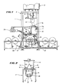
- the reference numeral 1 identifies the machine.
- the machine 1 is adapted to manufacture filter packs 10 (Figure 14) and includes an overhead main hopper 2 that can be located at a top edge of frame F such as about fifteen feet (5 m) above the coffee filter manufacturing machine. Downwardly extending bins 3 and 4 are provided beneath the main hopper 2 to receive coffee C therein. While the invention has been described for the manufacturer of coffee filled filter packs 10, the packs 10 can be filled with other beverages or foods such as hot chocolate or tea and the like.
- the coffee C ( Figure 6) is then transmitted from hopper 2 through a connected series of the bins 3 and 4.
- the bin 4 has dual side-by-side outlets 5,5.
- the bin outlets 5,5 function to deliver coffee C to a pair of side-by-side mounted dual conveyors 6,6.
- the conveyors 6,6 are driven by identical belt driven drives 7,7 all as seen in Figure 1.
- a control panel 8 is provided for regulating the operation of the conveyors.
- the conveyors each are connected to a speed control on the control panel 8 so that the operator can individually speed up or slow down the running speed of the conveyor so that the amount of coffee C can be regulated as it is being moved from the bin 4 through the dual outlets 5,5 and then from the dual conveyors 6,6 to dual chutes 9,9.
- the dual chutes 9,9 are provided with dual discharge orifices 11,11 for discharge into the interior of a circular filling wheel 13 as seen in Figure 2.
- dual drives 7,7 each include a direct current drive motor 12 for operating a belt drive 7a.
- Each conveyor 6 has its own direct drive and a special variable speed control is operated from the control panel 8 for regulating the drive.
- the coffee or other food is conveyed to the conveyor and the quantity of the coffee unloaded on the conveyor can be regulated and where it is desired that a greater amount of coffee be delivered to the circular filling wheel the drive can be run faster and where a smaller amount of food is desired than the conveyor speed can be decreased. It is in this way that the amount of coffee delivered to the filling wheel 13 can be regulated.
- the filling wheel 13 is driven so as to rotate in a clockwise direction.
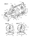
- the wheel 13 has land areas 14 provided with circumferentially spaced rows of wheel chutes or slots 15 ( Figures 4, 5 and 6).
- Each wheel chute or slot 15 is adapted to deliver or gravity feed a measured predetermined amount of coffee C to a radially aligned web pocket 23 to be filled as hereafter discussed.
- a stationary scraper 16 positioned interiorally of the circular filling wheel 13 and mounted on filling wheel drive shaft 14a.
- the scraper 16 cofunctions with wheel 13 and the chutes or slots 15 so as to operate to insure that only a predetermined volumetric amount of coffee C will ultimately be received into the web pouches 23.
- the coffee C is then allowed to be unloaded or scraped from the land areas and gravity fed into the pouches 23 formed in the continuously moving coffee paper web 17 as just described above.
- the filling wheel 13 is driven relative to the stationary scraper 16 to cause the wheel chutes or slots 15 to be emptied by the force of gravity as the filling wheel and the scraper causes the coffee C on the lands 14 to fall through the chutes or slots 15 in the filling wheel 13 into the pouches in radial underlying alignment therewith.
- the pouch filling operation occurs at an approximate 6 o'clock position on the filling wheel ( Figures 6 and 7).
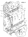
- the continuous coffee paper webs 17,17 are trained from a roll relatively unstretchable filter paper or paper stock 20 beneath and over a pair of guide rollers 21,21 and then about an underlying larger drum 18.
- the drum 18 has suction applied interiorally of it for sucking the paper webs 17,17, at predetermined intervals, into row of drum pockets 19 that are provided.
- the filling wheel 13 is caused to unload its contents on the underlying moving web of paper 17 that has deep paper pockets 23 in it.
- a paper slitter 40 ( Figure 4) can be employed to slit the web 17a in half forming the side-by-side webs 17,17 to facilitate the formation of the deep paper pockets 23 as will be further discussed hereafter.
- a second web of material 22 is fed onto the big wheel or drum 18 by web training or guide rollers 21,21 and in overlying abutment with the underlying moving slit webs 17,17 of coffee filled pockets 23 to provide closed or heat sealed filled pouches 10.
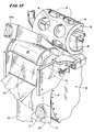
- An air blower and heater assembly 24 is provided having hoses on air line 24a with a hooded outlet 25 ( Figure 12) in the general vicinity of the area where the two bottom and upper webs 17,17 and 22 come together to cause the webs to then be heated sealed and assembled together and in this manner sealing the coffee in closed or heat sealed pockets.
- the air blower and heater assembly 24, and the hooded outlet 25 co-act so that heat can be applied to the upper web 22.
- Both webs 17,17 and 22 are of the same composition of material.
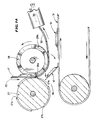
- the sealed webs 17 and 22 carrying the heat sealed filled pouches 10 are trained downwardly at right angles to a horizontal radius or point P of the wheel and they are caused to go into a cutting station 26 which has circular die cutters or cookie-type cutters 27 and 28 (Figure 13).
- the cutters 27 include circumferentially spaced knives 27a and the cutters 28 are provided with circumferentially spaced lands 28a.
- the knives on the cutter 27 and the lands or anvils on the cutters 28 co-act when engaged together as shown in Figure 14 to cut the webs 17,17 to cut out each of the coffee filter packs 10 as seen in Figure 14.
- These filled filter packs 10 then are moved onto a conveyor 31 which takes them to a coffee can filling station (not shown) where the cans are filled with a preselected number of the filled filter packs 10.
- Any suitable power source (not shown) can be connected to drive the meshed gears 29 and 30.
- a suction head 34 (Figure 13) is positioned just downstream of the die cutter area or the cutting station 26. Excellent results can be attained where the drum pockets and the web pouches are each 10.16 cm in diameter and each have a depth of 1.59 cm at center. It is further noted that at the can or container filling station (not shown), the so-called over wrap cans are in reality of a paper composition. The cans are called “Ceka" containers.
- the packaging line may include a can or carton machine for receipt of the filter packs produced by the machine 1.
- the "Ceka” (a trade name for a "Ceka” can for coffee and the like) line of equipment forms the containers, then the containers are moved along a conveyor and hand filled with a predetermined number of filter packs. Thereafter, the containers are moved on a conveyor into a gas chamber for substituting the atmosphere contained in the open ended containers whereby a nitrogen atmosphere is put into the containers.
- This gas flush system is not part of the development but it can be made part of the overall line of equipment used to produce sealed containers filled with the filled filter packs or packages 10.
- gas filled coffee filled containers can be then transported to another machine which puts lids onto the coffee containers.
- the lid assembly can be of a so-called double lid type. Initially, the first lid can be formed in the "Ceka" indexing lid forming section of the machine. The filled and sealed containers can then be transmitted to another station where the containers are provided with a lid which closes the partially open end of a container (not shown). The top or closing lid (not shown) is press fitted onto the open end of the container. Beneath the final lid is of course a pull away lid that a consumer breaks to gain access to the contents of the container. Once the interior lid is broken, the exterior lid can then be used to provide a temporary closure for the container so that the coffee can be kept as fresh as possible.
- the manufacturing line can fill each carton with twelve (12) containers or "Ceka" cans with each having ten (10) pouches in the container. It is further contemplated that the containers will be processed so as to have a preselected atmosphere such as nitrogen therein to maintain the fresh character of the coffee.
- the belt is an important element in connection with the formation of the pouches.
- the paper is placed up against the drum and the belt is then placed on top of the paper and the two travel along the surfaces of the drum at the same time.
- a vacuum is drawn by a suction motor 42 through a suction head 36 ( Figure 10) forming the pouch and the vacuum being drawn through the paper and pulling the belt down provides a well formed pouch.
- Arrows 43 in Figure 9 diagramatically show the way in which the suctions acts against the impervious rubber belt segment 37 to draw it and the web paper 17 into the drum cavity 19.
- the drum cavity 19 has a perforated screen-like member 44 that provides a bottom surface 45 against which the belt segment 37 and the web paper 17 are drawn into the drum cavity 19.
- the suction can freely act through the performations 46 in screen-like member 44.
- the pouch and the belt then separate and the filling step follows.
- the rotary drum 18 has a female shape or drum cavity 19 to provide a female form.
- a flexible rubber belt 38 is positioned in intimate contact with the drum and the belt co-rotates with the drum.
- the web paper or film on the drum can be slit in half and one piece of paper 17,17 is provided for each row on the drum 18.
- the vacuum is turned on, since the web paper 17,17 is porous the vacuum acts through the paper and it sucks the flexible rubber belt segment 37 into the cavity, thus drawing the paper into the cavity.
- the paper webs 17,17 are "crinkled” and relatively non-stretchable but the “crinkles” can flatten a bit and the web can be drawn from paper areas surrounding where the suction is applied to the web paper 17, 17 to permit the crinkled non-stretchable filter paper to be reshaped inside the drum cavities to provide pouches of a predetermined circumference and depth so as to be capable of fuctioning as a beverage filter or a filled coffee filter pack 10.
- the rubber belt 38 used form the filter paper into the drum cavities is a 0.04 cm thick Buna-N commercial grade rubber.
- the rubber belt 38 can be cut from sheeting and its belt ends can be glued together to form an endless belt.
- a 2.54 cm wide timing belt (not shown) can be glued to carry the rubber sheeting continuously around timing belt pulleys 41 and in contact with the main drum 18.
- the web 17 is slit so that the crinkled paper can be pulled from all sides of each of the drum cavities 19 as shown at 47,47 ( Figure 11) into the cavity 19 for forming each of the pouches 23 in the paper webs 17,17. If the web 17 were a solid piece from the center of the unslit web 17a with the film or paper trying to go both directions the paper web would have to be pulled from the outer edges to form the cavity or pouch 23.
- Grade 9926 Material Composition Polypropylene pulp and natural fibers
- Grade 9926 is a two-phase, light weight permeable heat seal tissue comprised of thermoplastic fibers, abaca pulp and other selected cellulose fibers. It offers, high wet-strength, excellent taste neutrality, and features maximum extraction while exhibiting good particle rentention. All materials used to manufacture grade 9926 are certified to be in accordance with 21 CFR 176.170, components of paper and paperboard in contact with aqueous and fatty foods.
- the filter paper is approximately 0.0762 mm thick and, the rolls are 29.21 cm wide before it is slit on our machine to approximately 14.6 cm wide.
- the paper used in the webs 17 and 22 is a manila hemp base material made from fibers from abaca which are a natural blend of material somewhat like a plant which has high stretch rations and so that a polypropylene fiber has been added which reduces both stretch and gives the ability to heat seal the material to itself to form the filter packs 10.
- the material is a web that has been formed with a micro creep to give it between six and eight percent elongations so that it can be formed in a cavity on the forming side of the filling wheel 13 for forming the pouches 23 in the lower web 17 as shown in Figures 8 and 9.
- Dexter Grade 9926 material include a composition of polypropylene pulp and natural fibers.
- the roll width may be 29.21 cm, and the roll length may be 1,279.6 m.
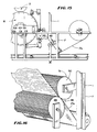
- FIGs 15 and 16 there is illustrated a modified machine 1.
- the machine is illustrated as being provided with an apparatus 48 including a pair of rollers 49 and 50 which rollers 49 and 50 are provided with circumferentially spaced paper forming ribs 51.
- an apparatus 48 including a pair of rollers 49 and 50 which rollers 49 and 50 are provided with circumferentially spaced paper forming ribs 51.
- the web 17a As the web 17a is drawn through the machine 1, the web 17a passes between the rollers 49 and 50, and the ribs 51 on the rollers 49 and 50 serve to form so-called transverse "crinkles" in the paper.
- uncrinkled paper can be converted into crinkled paper so that a relatively non-stretchable type of paper can be used in the machine 1 to form pouches 23 in the manner previously described and illustrated as shown in Figures 9, 10 and 11.
- ribs 51 on the respective rollers 49 and 50 can interact and mesh to form the transverse "crinkles" in the paper web 17a.
- Another pair of rollers can be provided to also form longitudinally extending ribs in the paper 17a, if desired.
- a scraper lock out device 52 is provided as shown in Figures 6 and 7.
- the lock out device includes a bar 53 which extends parallel to the filling wheel drive shaft 14a.
- the bar 53 is fixedly mounted to a pair of mounting blocks 54 ( Figure 5) mounted at opposite ends of the filling wheel drive shaft 14a.
- the filling wheel drive shaft 14a has bearings indicated at 55 which are also mounted on the support blocks 54 at opposite ends as previously described.
- the bar 53 has an angle 56 that is secured by fasteners 57 to the bar. Another leg of the angle 56 is in turn attached to stationary shaft 58.
- the scraper 16 is mounted to the stationary shaft 58 in fixed or stationary assembly. By mounting the scraper 16 in the manner illustrated in Figures 5, 6 and 7, the scraper can be held in a fixed non-rotating position.
- the invention can be used for producing filter packs 10 of coffee as disclosed herein.
- the machine 1 would probably work on other papers, the invention contemplates, in one form, that the paper is porous and it allows the suction head 36 to suck the air through the paper and pull the segment 37 of the driven rubber belt 38 down into the wheel cavity 19. Once the paper is formed and the vacuum is released, the air can pass through the porous paper (leaving it in the cavity 19) while the rubber belt segment 37 returns to its original unstretched position ( Figure 11).
- the invention involves the use of filter or porous paper. It is further contemplated that the invention can also be used for forming non-porous paper.
- the apparatus for causing the coffee to fall into the filling wheel pockets 23 operates so that the pocket diameter on the wheel 13 is smaller (1.27 cm) than the diameter of the pouch 23 that is to be filled whereby coffee is piled up in the center of the drum 18 so that it can be caused to fall into a controlled manner into the pouch 23 with a minimum of dusting to the paper area surrounding the web pouch being filled.
- the opening 15 in wheel 13 is smaller in diameter than the pouches 23.
Landscapes
- Engineering & Computer Science (AREA)
- Mechanical Engineering (AREA)
- Quality & Reliability (AREA)
- Containers And Plastic Fillers For Packaging (AREA)
- Auxiliary Devices For And Details Of Packaging Control (AREA)
Claims (14)
- Machine pour former, remplir et fermer en continu des emballages (10) à partir d'une bande continue de papier thermo-adhésif (17a), laquelle machine comprend un tambour rotatif (18), avec un ensemble de douilles (19) de formation de poches prévues dans la surface extérieure dudit tambour, un moyen d'alimentation en papier pour entraîner le papier sur le tambour et au-dessus des douilles (19) précitées, un moyen (13) pour remplir les poches de papier (23) avec un produit pendant que les poches se trouvent sur le tambour, un moyen pour entraîner une bande de papier de couverture (22) par dessus les poches remplies de produit dans la bande de papier continue, et des moyens (24, 25) pour faire adhérer la bande de couverture sur les poches remplies afin de former des emballages fermés, caractérisée en ce qu'elle comprend une courroie sans fin souple (38) qui est entrainée et vient en contact avec une partie périphérique de la surface extérieure du tambour précité, des moyens d'aspiration (36, 42) pour tirer les zones de ladite bande qui couvrent les douilles (19) du tambour dans lesdites douilles, la bande de papier non-extensible étant maintenue entre lesdites zones de la courroie et lesdites douilles (19) du tambour de manière à former les poches de papier (23) précitées, les moyens d'aspiration (36, 42) pouvant être mis hors service pour permettre à la courroie (38) de se retirer élastiquement de dedans les douilles (19) du tambour après que les poches de papier (23) ont été formées.
- Machine suivant la revendication 1, dans laquelle le moyen pour remplir les poches de papier comprend une roue de remplissage rotative (13), des conduits d'alimentation en produit (9) s'étendant jusque dans la roue de remplissage (13) à partir des côtés opposés axialement de ladite roue, des orifices de décharge dans le tambour de remplissage étant écartées l'une de l'autre sur le pourtour du tambour par des plages (14) espacées circonférenciellement, lesdites plages étant positionables en dessous des extrémités de décharges des conduits d'alimentation en produit pour recevoir le produit, et un moyen grattoir (16) pour évacuer le produit des plages précitées de manière que le produit tombe par gravité dans les poches de papier se trouvant dessous durant leur rotation conjointe.
- Machine suivant la revendication 1 ou 2, dans laquelle les douilles du tambour sont munies de moyens d'aération (46) pour permettre à l'aspiration de s'établir à travers ceux-ci et pour procurer un support solide pour les poches de papier lorsque les moyens d'aspiration leur appliquent un courant d'aspiration.
- Machine suivant l'une quelconque des revendications précédentes, dans laquelle les moyens d'aspiration sont montés à l'intérieur du tambour rotatif et sont fixes par rapport à celui-ci, lesdits moyens d'aspiration étant périodiquement en communication avec les douilles précitées pour former lesdites poches.
- Machine suivant l'une quelconque des revendications précédentes, dans laquelle un moyen (40) est prévu pour couper la bande continue de papier thermo-adhésif (17a) suivant sa longueur de manière à créer deux rubans contigus (17, 17) de papier thermo-adhésif avant que la bande de papier ne vienne en contact avec la surface du tambour, les deux rubans étant amenés ensuite en contact avec la courroie sans fin souple (38) de manière à former les rubans continus adjacents de poches de papier.
- Machine suivant l'une quelconque des revendications précédentes, dans laquelle le moyen de remplissage comprend une roue de remplissage circulaire (13) ayant des ouvertures de remplissage (15) espacées circonférenciellement, ces ouvertures étant disposées au-dessus des et coïncidant avec les douilles précitées du tambour (18) durant leurs mouvements de rotation, et un organe grattoir fixe (16) positionné de manière centrale dans la roue de remplissage (13), ledit organe grattoir étant disposé de manière à coopérer avec la roue de remplissage afin de permettre une opération de remplissage par gravité.
- Machine suivant la revendication 6, dans laquelle l'organe grattoir (16) coopère avec les plages (14) précitées afin de décharger le produit de ces plages (14) lorsque celles-ci et le tambour se trouvent approximativement dans une position 6 heures.
- Machine suivant la revendication 6, dans laquelle les goulottes d'alimentation en produit se terminent par deux orifices de décharge (11, 11) situés à l'intérieur de la roue de remplissage pour amener du produit par gravité depuis les côtés opposés axialement jusque sur les plages (14) précitées entre les douilles afin de permettre à l'organe grattoir (16) de pousser ensuite le produit se trouvant sur lesdites plages pour le faire tomber dans les poches, le tambour rotatif (18) se trouvant en dessous de la roue de remplissage, la rotation de celle-ci amenant périodiquement ses ouvertures (15) en alignement avec les douilles (19) du tambour grâce à la rotation de la roue de remplissage et du tambour précités.
- Procédé pour former, remplir et fermer des emballages (10) comprenant les étapes suivantes : déplacement d'une première bande continue de papier thermo-adhésif vers une zone de formation d'emballages, emplissage des emballages avec du produit, amenée d'une bande de papier de couverture en superposition avec la première bande de papier, scellage de la bande de couverture superposée par dessus les zones des poches afin de former des emballages remplis et fermés, et découpage des emballages fermés des bandes de papier thermo-adhésif afin de produire des emballages individuels, caractérisé par l'utilisation de papier thermo-adhésif non extensible, le maintien de la bande de papier précitée entre une courroie souple extensible et la zone formant les emballages, l'aspiration consécutive des zones superposées du papier et de la courroie dans les douilles de formation de poches de la zone de formation d'emballages de manière à former des poches contiguës, et la coupure de l'aspiration de manière à permettre aux zones détendues de la courroie de se retirer des poches.
- Procédé suivant la revendication 9, caractérisé en outre par l'amenée du produit à tomber par gravité dans des ouvertures d'une roue de remplissage, ces ouvertures ayant un diamètre plus petit que celui des poches à remplir de manière que le produit se trouve distribué d'une façon contrôlée dans la poche avec un minimum de dispersion du produit de sorte que l'emballage peut être fermé sans gaspillage de produit.
- Procédé suivant la revendication 9, caractérisé par l'utilisation d'une bande de papier filtre d'environ 0,076 mm d'épaisseur.
- Procédé suivant la revendication 9, caractérisé en ce que la largeur de la bande sur les côtés opposés de chaque poche est réduite par une étape d'étirage par aspiration.
- Procédé suivant la revendication 9, caractérisé en ce que la bande de papier de couverture est chauffée et enroulée contre la première bande tout en laissant le produit et la première bande pratiquement non chauffée.
- Procédé suivant l'une quelconque des revendications 9 à 13, caractérisé par l'utilisation de papier filtre crêpé thermo-adhésif.
Applications Claiming Priority (2)
| Application Number | Priority Date | Filing Date | Title |
|---|---|---|---|
| US445458 | 1982-11-30 | ||
| US07/445,458 US5081819A (en) | 1989-12-04 | 1989-12-04 | Method and apparatus for manufacture and packaging of filter packs for use in a brew basket |
Publications (2)
| Publication Number | Publication Date |
|---|---|
| EP0432126A1 EP0432126A1 (fr) | 1991-06-12 |
| EP0432126B1 true EP0432126B1 (fr) | 1994-10-12 |
Family
ID=23768981
Family Applications (1)
| Application Number | Title | Priority Date | Filing Date |
|---|---|---|---|
| EP90870238A Expired - Lifetime EP0432126B1 (fr) | 1989-12-04 | 1990-12-04 | Dispositif et procédé pour former, remplir et fermer un emballage |
Country Status (4)
| Country | Link |
|---|---|
| US (1) | US5081819A (fr) |
| EP (1) | EP0432126B1 (fr) |
| CA (1) | CA2006747C (fr) |
| DE (1) | DE69013303T2 (fr) |
Cited By (2)
| Publication number | Priority date | Publication date | Assignee | Title |
|---|---|---|---|---|
| EP4378841A1 (fr) * | 2022-12-02 | 2024-06-05 | The Procter & Gamble Company | Procédé de fabrication d'un sachet soluble dans l'eau de détergent |
| US12703002B2 (en) | 2022-12-02 | 2026-08-11 | The Procter & Gamble Company | Process for making a fibrous water soluble product |
Families Citing this family (51)
| Publication number | Priority date | Publication date | Assignee | Title |
|---|---|---|---|---|
| US5459980A (en) * | 1989-04-28 | 1995-10-24 | A.G. (Patents) Limited | Manufacturing infusion packages |
| US5233813A (en) * | 1989-04-28 | 1993-08-10 | Ag (Patents) Limited | Manufacturing infusion packages |
| DE9318405U1 (de) * | 1993-12-01 | 1994-01-27 | Papierfabrik Schoeller & Hoesch GmbH, 76593 Gernsbach | Filtermaterial |
| DE4424112A1 (de) * | 1994-07-08 | 1996-01-11 | Raytest Isotopenmesgeraete Gmb | Verfahren zur Herstellung eines Probenträgers |
| DE19517616A1 (de) * | 1995-05-13 | 1996-11-21 | Bosch Gmbh Robert | Vorrichtung zum Verbinden zweier Packstoffbahnen |
| US5694741A (en) * | 1995-06-07 | 1997-12-09 | Southpac Trust International Inc. | Easter grass bag forming |
| US5678388A (en) * | 1995-06-07 | 1997-10-21 | Southpac Trust International, Inc. | Apparatus and method for making and bagging decorative grass |
| US5656233A (en) * | 1995-06-07 | 1997-08-12 | Southpac Trust International, Inc. | Method for making low-density decorative grass |
| ATE197375T1 (de) * | 1995-09-27 | 2000-11-11 | Teepack Spezialmaschinen | Verfahren und vorrichtung zum aromatisieren von tee und teeähnlichen erzeugnissen |
| IT1277108B1 (it) * | 1995-12-19 | 1997-11-04 | Opem Srl | Macchina per produrre, da film continuo, cialde di caffe' rotonde, e non, per macchine automatiche da caffe' espresso |
| US5826633A (en) | 1996-04-26 | 1998-10-27 | Inhale Therapeutic Systems | Powder filling systems, apparatus and methods |
| US6182712B1 (en) | 1997-07-21 | 2001-02-06 | Inhale Therapeutic Systems | Power filling apparatus and methods for their use |
| ES2167124B1 (es) * | 1998-10-23 | 2003-04-01 | Laguna Vicente Gomez | Maquina para la fabricacion de envases con contenido consumible. |
| EP1142785B1 (fr) * | 1998-12-28 | 2009-02-25 | Kao Corporation | Procede de production de pochettes a fluide |
| DE19910366A1 (de) * | 1999-03-09 | 2000-09-14 | Kimberly Clark Gmbh | Verpackungsmaschine und Verfahren zum Verpacken eines Schüttgutes |
| DE10023590A1 (de) * | 2000-05-13 | 2001-11-15 | Bosch Gmbh Robert | Verfahren und Vorrichtung zum Herstellen von Blisterbahnen |
| US7125828B2 (en) | 2000-11-27 | 2006-10-24 | The Procter & Gamble Company | Detergent products, methods and manufacture |
| US8940676B2 (en) | 2000-11-27 | 2015-01-27 | The Procter & Gamble Company | Detergent products, methods and manufacture |
| US8283300B2 (en) | 2000-11-27 | 2012-10-09 | The Procter & Gamble Company | Detergent products, methods and manufacture |
| JP4707933B2 (ja) | 2000-11-27 | 2011-06-22 | ザ プロクター アンド ギャンブル カンパニー | 食器洗浄方法 |
| JP2005014978A (ja) * | 2003-06-26 | 2005-01-20 | Toa Kiko Kk | 磁性体粉末の連続包装機および包装方法 |
| ITBO20030474A1 (it) * | 2003-08-01 | 2005-02-02 | Roberto Conti | Metodo e apparecchiatura per la realizzazione di cialde per prodotti da infusione. |
| ITBO20030475A1 (it) * | 2003-08-01 | 2005-02-02 | Roberto Conti | Dispositivo per il dosaggio e la formatura di cialde per prodotti da infusione. |
| ITBO20030666A1 (it) | 2003-11-12 | 2005-05-13 | Aroma System S R L | Confezionatrice di cialde in cartafiltro. |
| ITBO20030735A1 (it) * | 2003-12-05 | 2005-06-06 | Roberto Conti | Apparecchiatura per la formazione di cialde per prodotti da infusione |
| ITBO20040548A1 (it) * | 2004-09-07 | 2004-12-07 | Goglio Spa | Macchina per realizzare confezioni di prodotti da infusione |
| US8840390B2 (en) * | 2007-06-29 | 2014-09-23 | Risco Usa Corporation | Machine for the production of formed patties with a hand made appearance, and method for interleaving paper and stacking |
| IT1394271B1 (it) * | 2009-05-25 | 2012-06-06 | Ima Flavour S R L Ora Ima Ind S R L | Gruppo di compressione - incisione - taglio a rulli |
| DE202011111008U1 (de) | 2010-10-13 | 2018-03-21 | Drylock Technologies Nv | Absorbierende Struktur |
| US11020280B2 (en) | 2010-10-13 | 2021-06-01 | Romanova Bvba Starter | Method and Apparatus for Producing Composite Structure |
| EP2444044A1 (fr) * | 2010-10-13 | 2012-04-25 | Romanova bvba starter | Procédé et appareil pour la production de structures absorbantes |
| EP2444045A1 (fr) * | 2010-10-20 | 2012-04-25 | Vynka Bvba | Procédé et appareil de production d'une structure absorbante sans danger pour l'environnement |
| US9039589B2 (en) | 2011-01-22 | 2015-05-26 | Adrian Rivera | Beverage pod packaging manufacturing machine |
| US8875477B2 (en) * | 2011-01-22 | 2014-11-04 | Adrian Rivera | Beverage pod manufacturing machine |
| DE102011085283B4 (de) * | 2011-02-21 | 2025-03-27 | Syntegon Technology Gmbh | Vorrichtung zum Dosieren von pulverförmigem Füllgut |
| EP2532777A1 (fr) * | 2011-05-19 | 2012-12-12 | Autoneum Management AG | Dispositif de moulage d'un matériau fibreux |
| US9428328B2 (en) | 2011-09-01 | 2016-08-30 | 2266170 Ontario Inc. | Beverage capsule |
| ES2714629T3 (es) * | 2012-02-21 | 2019-05-29 | Cloud Packaging Solutions Llc | Sistemas y métodos de envasado de polímeros |
| PT2660161T (pt) * | 2012-05-04 | 2017-11-09 | Tpresso Ag | Acondicionamento de folhas secas em cápsulas herméticas |
| EP2874796B1 (fr) * | 2012-07-18 | 2015-10-21 | Unilever PLC | Paquets d'infusion et procédé pour leur fabrication |
| ITBO20120594A1 (it) * | 2012-10-31 | 2014-05-01 | Ima Ind Srl | Apparato e metodo per alimentare capsule vuote ad una macchina confezionatrice |
| CA2833096C (fr) | 2012-11-12 | 2016-05-31 | 2266170 Ontario Inc. | Capsule pour boisson et procede et systeme pour sa fabrication |
| CA2842774A1 (fr) * | 2013-02-13 | 2014-08-13 | Multi-Pack Solutions | Systemes et methodes de formation d'ouvertures dans les emballages hydrosolubles |
| EP2981198A4 (fr) | 2013-04-03 | 2016-11-16 | 2266170 Ontario Inc | Machine à dosettes et composants |
| WO2014186897A1 (fr) | 2013-05-23 | 2014-11-27 | 2266170 Ontario Inc. | Logement de capsule |
| CA2922824C (fr) | 2013-08-20 | 2021-05-18 | 2266170 Ontario Inc. | Capsule contenant un agent de dosage et son systeme et procede de fabrication |
| US10314319B2 (en) | 2013-11-20 | 2019-06-11 | 2266170 Ontario Inc. | Method and apparatus for accelerated or controlled degassing of roasted coffee |
| CA2943295C (fr) | 2014-03-21 | 2022-06-28 | 2266170 Ontario Inc. | Capsule avec chambre de trempage |
| CA2871901C (fr) | 2014-10-24 | 2021-07-20 | Multi-Pack Solutions | Systemes et methodes de formation de paquets hydrosolubles a double couche |
| MX2020013483A (es) * | 2018-06-22 | 2021-02-26 | Church & Dwight Co Inc | Sistema y metodo para llenar un paquete con camaras. |
| EP4493398A1 (fr) * | 2022-03-18 | 2025-01-22 | Sarong Societa' Per Azioni | Appareil et procédé de fabrication d'un récipient |
Family Cites Families (15)
| Publication number | Priority date | Publication date | Assignee | Title |
|---|---|---|---|---|
| US2033201A (en) * | 1932-11-07 | 1936-03-10 | Acme Steel Co | Method of and apparatus for wrapping annular objects |
| GB674886A (en) * | 1949-04-20 | 1952-07-02 | Ivers Lee Co | Improvements in and relating to machines for fabricating packages |
| US2997927A (en) * | 1959-02-09 | 1961-08-29 | Peerless Machine & Tool Co Inc | Formed paper dish and method for making same |
| US3038282A (en) * | 1960-07-05 | 1962-06-12 | American Cyanamid Co | Capsules of soft plastic containing granules |
| US3218776A (en) * | 1961-09-11 | 1965-11-23 | Cloud Machine Corp | Packaging method and apparatus |
| US3192684A (en) * | 1962-03-12 | 1965-07-06 | Melikian Inc Rudd | Apparatus for making package tapes |
| US3353329A (en) * | 1964-08-11 | 1967-11-21 | Cloud Machine Corp | Method of and apparatus for packaging elongated articles such as nipples |
| US3184895A (en) * | 1964-08-04 | 1965-05-25 | Morton Salt Co | Method of packaging |
| DE1903754U (de) * | 1964-08-08 | 1964-11-05 | Hauni Werke Koerber & Co Kg | Vorrichtung zum dosieren und einfuellen eines kornigen gutes. |
| US3759011A (en) * | 1972-05-04 | 1973-09-18 | Reed Lane Inc | Packaging machine for packaging uniform articles such as pharmaceutical tablets |
| US4375146A (en) * | 1979-06-11 | 1983-03-01 | International Automated Machinery, Inc. | Continuous rotary machine and method for forming, filling, and sealing package of laminated sheet material |
| EP0188832B1 (fr) * | 1984-11-28 | 1989-09-27 | The Procter & Gamble Company | Procédé et dispositif pour fabriquer des sachets poreux contenant un produit granulaire |
| US4571924A (en) * | 1985-04-29 | 1986-02-25 | The Procter & Gamble Company | Method and apparatus of manufacturing porous pouches containing granular product |
| IT8523784V0 (it) * | 1985-11-11 | 1985-11-11 | Rossi Luigi | Perfezionata macchina confezionatrice di cialde di carta di filtro atte alla preparazione di infusi. |
| EP0338111B1 (fr) * | 1988-04-21 | 1993-06-30 | Koyo Disposable Goods Company | Procédé de production d'articles sanitaires et dispositif pour l'utilisation de cette méthode |
-
1989
- 1989-12-04 US US07/445,458 patent/US5081819A/en not_active Expired - Lifetime
- 1989-12-28 CA CA002006747A patent/CA2006747C/fr not_active Expired - Lifetime
-
1990
- 1990-12-04 EP EP90870238A patent/EP0432126B1/fr not_active Expired - Lifetime
- 1990-12-04 DE DE69013303T patent/DE69013303T2/de not_active Expired - Lifetime
Cited By (2)
| Publication number | Priority date | Publication date | Assignee | Title |
|---|---|---|---|---|
| EP4378841A1 (fr) * | 2022-12-02 | 2024-06-05 | The Procter & Gamble Company | Procédé de fabrication d'un sachet soluble dans l'eau de détergent |
| US12703002B2 (en) | 2022-12-02 | 2026-08-11 | The Procter & Gamble Company | Process for making a fibrous water soluble product |
Also Published As
| Publication number | Publication date |
|---|---|
| CA2006747C (fr) | 1997-01-14 |
| US5081819A (en) | 1992-01-21 |
| DE69013303D1 (de) | 1994-11-17 |
| DE69013303T2 (de) | 1995-05-11 |
| CA2006747A1 (fr) | 1991-06-04 |
| EP0432126A1 (fr) | 1991-06-12 |
Similar Documents
| Publication | Publication Date | Title |
|---|---|---|
| US5081819A (en) | Method and apparatus for manufacture and packaging of filter packs for use in a brew basket | |
| US3828660A (en) | Machine for making ice cream cookie sandwiches and similar food products | |
| US4067173A (en) | Packaging machine | |
| EP0921978B1 (fr) | Dispositif d'emballer tabac finement hache et humidifie | |
| US4055032A (en) | Process for forming sealed liquid filled bags | |
| US6635145B2 (en) | Packaging filler product | |
| US6058681A (en) | Method of making heat sealed produce bags | |
| US5440860A (en) | Method and apparatus for forming and hermetically sealing slices of food items | |
| US5112632A (en) | Method and apparatus for forming and hermetically sealing slices of food items | |
| US3597898A (en) | Packaging machine | |
| EP2404833B1 (fr) | Distributeur automatique de coussin d'air | |
| US6506429B1 (en) | Bag with mesh wall | |
| US3751875A (en) | Apparatus for filling, sealing and dispensing bags | |
| CN206984573U (zh) | 一种多类型包装一体机 | |
| EP0892714B1 (fr) | Rouleau de sacs et procede et dispositif de production de ce rouleau | |
| US3731451A (en) | Filter plug forming and bagging machine | |
| US3667188A (en) | Method and apparatus for forming and filling individual pouches | |
| US2721017A (en) | Method and means for continuous filling, severing and packaging of flexible containers arranged in strip form | |
| CN107284777A (zh) | 一种多类型包装一体机及其包装方法 | |
| US4301639A (en) | Apparatus and method for producing a container for food and the like | |
| GB2351035A (en) | Bags with tongues and method and apparatus for making them | |
| US2928221A (en) | Packaging machine | |
| US6073422A (en) | Filling and lidding machine and method | |
| US3757620A (en) | Cutting apparatus | |
| JP2002068110A (ja) | 供給装置 |
Legal Events
| Date | Code | Title | Description |
|---|---|---|---|
| PUAI | Public reference made under article 153(3) epc to a published international application that has entered the european phase |
Free format text: ORIGINAL CODE: 0009012 |
|
| AK | Designated contracting states |
Kind code of ref document: A1 Designated state(s): DE GB IT SE |
|
| 17P | Request for examination filed |
Effective date: 19911119 |
|
| 17Q | First examination report despatched |
Effective date: 19930326 |
|
| GRAA | (expected) grant |
Free format text: ORIGINAL CODE: 0009210 |
|
| AK | Designated contracting states |
Kind code of ref document: B1 Designated state(s): DE GB IT SE |
|
| REF | Corresponds to: |
Ref document number: 69013303 Country of ref document: DE Date of ref document: 19941117 |
|
| ITF | It: translation for a ep patent filed | ||
| PG25 | Lapsed in a contracting state [announced via postgrant information from national office to epo] |
Ref country code: SE Effective date: 19950112 |
|
| PLBE | No opposition filed within time limit |
Free format text: ORIGINAL CODE: 0009261 |
|
| STAA | Information on the status of an ep patent application or granted ep patent |
Free format text: STATUS: NO OPPOSITION FILED WITHIN TIME LIMIT |
|
| 26N | No opposition filed | ||
| REG | Reference to a national code |
Ref country code: GB Ref legal event code: IF02 |
|
| PGFP | Annual fee paid to national office [announced via postgrant information from national office to epo] |
Ref country code: GB Payment date: 20091224 Year of fee payment: 20 |
|
| PGFP | Annual fee paid to national office [announced via postgrant information from national office to epo] |
Ref country code: IT Payment date: 20091229 Year of fee payment: 20 |
|
| PGFP | Annual fee paid to national office [announced via postgrant information from national office to epo] |
Ref country code: DE Payment date: 20100112 Year of fee payment: 20 |
|
| REG | Reference to a national code |
Ref country code: GB Ref legal event code: PE20 Expiry date: 20101203 |
|
| PG25 | Lapsed in a contracting state [announced via postgrant information from national office to epo] |
Ref country code: GB Free format text: LAPSE BECAUSE OF EXPIRATION OF PROTECTION Effective date: 20101203 |
|
| PG25 | Lapsed in a contracting state [announced via postgrant information from national office to epo] |
Ref country code: DE Free format text: LAPSE BECAUSE OF EXPIRATION OF PROTECTION Effective date: 20101204 |