EP0432149A2 - Gehäuse mit Drehgelenk für Staubsaugermundstück - Google Patents
Gehäuse mit Drehgelenk für Staubsaugermundstück Download PDFInfo
- Publication number
- EP0432149A2 EP0432149A2 EP91400244A EP91400244A EP0432149A2 EP 0432149 A2 EP0432149 A2 EP 0432149A2 EP 91400244 A EP91400244 A EP 91400244A EP 91400244 A EP91400244 A EP 91400244A EP 0432149 A2 EP0432149 A2 EP 0432149A2
- Authority
- EP
- European Patent Office
- Prior art keywords
- housing
- sleeve
- bowl
- vacuum cleaner
- substantially vertical
- Prior art date
- Legal status (The legal status is an assumption and is not a legal conclusion. Google has not performed a legal analysis and makes no representation as to the accuracy of the status listed.)
- Granted
Links
- 238000000465 moulding Methods 0.000 claims abstract description 6
- 230000002093 peripheral effect Effects 0.000 description 3
- 238000002347 injection Methods 0.000 description 2
- 239000007924 injection Substances 0.000 description 2
- 208000031968 Cadaver Diseases 0.000 description 1
- 230000008878 coupling Effects 0.000 description 1
- 238000010168 coupling process Methods 0.000 description 1
- 238000005859 coupling reaction Methods 0.000 description 1
- 230000007547 defect Effects 0.000 description 1
- 230000008021 deposition Effects 0.000 description 1
- 239000000428 dust Substances 0.000 description 1
- 239000000835 fiber Substances 0.000 description 1
- 239000002991 molded plastic Substances 0.000 description 1
- 239000002245 particle Substances 0.000 description 1
- 230000000750 progressive effect Effects 0.000 description 1
- 238000007789 sealing Methods 0.000 description 1
- 210000002105 tongue Anatomy 0.000 description 1
- XLYOFNOQVPJJNP-UHFFFAOYSA-N water Substances O XLYOFNOQVPJJNP-UHFFFAOYSA-N 0.000 description 1
Images


Classifications
-
- A—HUMAN NECESSITIES
- A47—FURNITURE; DOMESTIC ARTICLES OR APPLIANCES; COFFEE MILLS; SPICE MILLS; SUCTION CLEANERS IN GENERAL
- A47L—DOMESTIC WASHING OR CLEANING; SUCTION CLEANERS IN GENERAL
- A47L9/00—Details or accessories of suction cleaners, e.g. mechanical means for controlling the suction or for effecting pulsating action; Storing devices specially adapted to suction cleaners or parts thereof; Carrying-vehicles specially adapted for suction cleaners
- A47L9/02—Nozzles
Definitions
- the present invention relates to improvements made to housings with a rotary coupling for a vacuum cleaner nozzle.
- a rotary connector housing for a vacuum cleaner nozzle generally has a top and a side wall, the rear part of which forms a body. This sleeve opening to the outside is intended to receive a tubing of a connector rigidly connected or articulated on a tubular handle of a vacuum cleaner.
- the connection tubing is mounted to rotate about an anteroposterior axis and immobilized in translation in the sleeve.
- the top of the housing forms a body with a substantially vertical internal conduit, communicating the aforementioned connection tubing with a window of a slip sole fitted and fixed under the housing, window which opens into a longitudinal channel suction from the sole.
- the molding reveals marks due to shrinkage, marks which compromise the aesthetics.
- the object of the present invention is to remedy these drawbacks: - by providing the necessary means to ensure a better flow of the gas flow and to reduce the risks of deposition of particles (dust, fibers, hair ...) in the nozzle and leakage outside, at the same time as these means allow easier molding, increase the rate injection and therefore reduce the cost price, eliminate apparent defects: shrinkage, injection point ...
- the rear wall of the housing forms a body with a sleeve in which is rotatably mounted and immobilized in translation a connection tube to a vacuum cleaner, this housing comprising a substantially vertical internal duct which opens at the top in the sleeve and at the bottom in a window of a sole normally fixed under said housing, and, in accordance with the invention, the conduit has an upper bend connected to the molding with the sleeve and projecting into a bowl formed hollow in the top of the housing for the passage of the part of the mold which defines the external shape of said bend, which reduces the pressure losses and thus improves the flow of the gas flow,
- the posterior and anterior walls of the conduit as well as the lateral walls of the latter are substantially vertical under the bottom of the bowl, while in the bowl above its bottom, the conduit is connected at the elbow by its substantially vertical front wall and by its converging side walls, the rear wall being integral with the sleeve.
- the bowl is closed by a clip-on cover extending substantially the top of the housing.
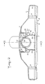
- a suction pipe 11 can be connected by its bent end 12 to a vacuum cleaner handle. Its free end 13 forms a tubular end piece which projects from a shoulder 14.
- the end piece 13 has cylindrical bearing surfaces 15 to 17 intended to be fitted into the sleeve 5. Between the bearing surfaces 15 and 16 are provided annular sealing lips 18 and an axial immobilization groove 19 separates the bearing surfaces 16 and 17.
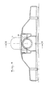
- the conduit 6 has at its base a rectangular section connected to the sleeve 5 by a vertical rear wall 20, by a vertical front wall 21 extended by an upper bend 22 (Figure 1) and by vertical side walls 23 extended by converging walls 24 connected to elbow 22 (figure 2).
- the duct 6 thus shaped connects the window 7 to the sleeve 5 with a progressive variation of the section and a guided deviation in the curve of the direction of flow.
- This conduit 6 is integral with the top 2 of the housing via a parallelepipedal bowl 25.
- the bottom 26 of the bowl is integral with the conduit 6, while the peripheral wall 27 of this bowl which is spaced from this conduit 6 is secured to the top 2 of the housing as well as to the upper half of the sleeve 5.
- the peripheral wall 27 delimits in the top 2 an opening 28 through which a part of the mold can pass, defining the shape of the upper outer portion of the sleeve 5 and of the conduit 6 as well as the inner shape of the bowl 25. It provision is made to close the opening 28 by means of a cover 29 which is positioned in a recess in the top 2 and which can be fixed in a removable manner by means of flexible tongues with teeth 30 clipped into slots 31 in the bowl 25.
- the cover 29 is integral with a lug 32 delimiting a semi-circular recess 33 whose diameter is substantially equal to the diameter of the bottom of the groove 19 of the end piece 13 of the tubing 11. Furthermore, a notch 34 is formed in the sleeve 5 and delimited by a sloping rear edge 36 which diverges upwards.
- the tab 32 of the cover 29 placed enters the groove 19 of the 'end piece 13 and immobilizes, by abutment against the rear edge 37 of said groove, in translation said end piece without opposing its rotation.
- the tab 32 is integral with inclined ramps 38 cooperating with the sloping rear edges 36 of the notches 34 of the sleeve 5.
- the front edges 35 of the notches can be aligned with the front edge 37 of the groove 19 of the nozzle 13 when the latter is in place so that the lug 32 and its ramps 38 are perfectly wedged in said notches.
Landscapes
- Engineering & Computer Science (AREA)
- Mechanical Engineering (AREA)
- Electric Vacuum Cleaner (AREA)
- Quick-Acting Or Multi-Walled Pipe Joints (AREA)
- Electric Suction Cleaners (AREA)
- Centrifugal Separators (AREA)
Applications Claiming Priority (2)
| Application Number | Priority Date | Filing Date | Title |
|---|---|---|---|
| FR8914305A FR2653654B1 (fr) | 1989-10-31 | 1989-10-31 | Boitier a raccord tournant pour suceur d'aspirateur. |
| FR8914305 | 1989-10-31 |
Related Parent Applications (3)
| Application Number | Title | Priority Date | Filing Date |
|---|---|---|---|
| EP19900403008 Division-Into EP0426534B1 (de) | 1989-10-31 | 1990-10-25 | Gehäuse mit Drehgelenk für Staubsaugermundstück |
| EP19900403008 Division EP0426534B1 (de) | 1989-10-31 | 1990-10-25 | Gehäuse mit Drehgelenk für Staubsaugermundstück |
| EP90403008.7 Division | 1990-10-25 |
Publications (3)
| Publication Number | Publication Date |
|---|---|
| EP0432149A2 true EP0432149A2 (de) | 1991-06-12 |
| EP0432149A3 EP0432149A3 (en) | 1991-08-21 |
| EP0432149B1 EP0432149B1 (de) | 1994-03-30 |
Family
ID=9386985
Family Applications (2)
| Application Number | Title | Priority Date | Filing Date |
|---|---|---|---|
| EP19910400244 Expired - Lifetime EP0432149B1 (de) | 1989-10-31 | 1990-10-25 | Gehäuse mit Drehgelenk für Staubsaugermundstück |
| EP19900403008 Expired - Lifetime EP0426534B1 (de) | 1989-10-31 | 1990-10-25 | Gehäuse mit Drehgelenk für Staubsaugermundstück |
Family Applications After (1)
| Application Number | Title | Priority Date | Filing Date |
|---|---|---|---|
| EP19900403008 Expired - Lifetime EP0426534B1 (de) | 1989-10-31 | 1990-10-25 | Gehäuse mit Drehgelenk für Staubsaugermundstück |
Country Status (4)
| Country | Link |
|---|---|
| EP (2) | EP0432149B1 (de) |
| DE (2) | DE69007758T2 (de) |
| ES (2) | ES2056418T3 (de) |
| FR (1) | FR2653654B1 (de) |
Cited By (4)
| Publication number | Priority date | Publication date | Assignee | Title |
|---|---|---|---|---|
| WO1994017720A1 (en) * | 1993-02-13 | 1994-08-18 | Vax Limited | Swivel joints primarily for mounting suction cleaner heads |
| EP0668044A1 (de) * | 1994-02-22 | 1995-08-23 | AEG Hausgeräte GmbH | Saugmundstück für Staubsauger |
| EP0983742A3 (de) * | 1998-09-02 | 2001-07-18 | Vorwerk & Co. Interholding GmbH | Staubsauger |
| GB2538842A (en) * | 2015-03-24 | 2016-11-30 | Wessel-Werk Gmbh | Sliding base plate for a vacuum cleaner nozzle |
Families Citing this family (3)
| Publication number | Priority date | Publication date | Assignee | Title |
|---|---|---|---|---|
| EP0749719B1 (de) * | 1995-06-22 | 2001-04-18 | Bosch-Siemens Hausgeräte GmbH | Lösbare Anordnung eines Funktionsteiles in einer Gehäuseöffnung eines Staubsaugers |
| DE19617415C2 (de) * | 1996-05-01 | 2001-06-21 | Wessel Werk Gmbh | Saugkopf an einem Staubsauger |
| GB2422092A (en) | 2005-01-18 | 2006-07-19 | Dyson Technology Ltd | Cleaning head for a vacuum cleaner |
Family Cites Families (6)
| Publication number | Priority date | Publication date | Assignee | Title |
|---|---|---|---|---|
| US2496813A (en) * | 1945-08-21 | 1950-02-07 | Electrolux Corp | Pipe joint |
| US2842794A (en) * | 1954-11-12 | 1958-07-15 | Electrolux Corp | Tapered multi-purpose nozzle |
| US3117338A (en) * | 1956-06-11 | 1964-01-14 | Filtex Corp | Suction nozzle |
| FR2535963B1 (fr) * | 1982-11-12 | 1986-06-20 | Olivier Ets Georges | Dispositif de montage tournant d'une tubulure aspirante sur un suceur d'aspirateur |
| DE3708503A1 (de) * | 1986-04-01 | 1987-10-08 | Siemens Ag | Staubsaugermundstueck |
| FR2599236B1 (fr) * | 1986-05-30 | 1989-03-10 | Olivier Ets Georges | Suceur d'aspirateur avec arrache-fils. |
-
1989
- 1989-10-31 FR FR8914305A patent/FR2653654B1/fr not_active Expired - Lifetime
-
1990
- 1990-10-25 EP EP19910400244 patent/EP0432149B1/de not_active Expired - Lifetime
- 1990-10-25 DE DE1990607758 patent/DE69007758T2/de not_active Expired - Fee Related
- 1990-10-25 ES ES90403008T patent/ES2056418T3/es not_active Expired - Lifetime
- 1990-10-25 ES ES91400244T patent/ES2054448T3/es not_active Expired - Lifetime
- 1990-10-25 EP EP19900403008 patent/EP0426534B1/de not_active Expired - Lifetime
- 1990-10-25 DE DE1990609004 patent/DE69009004T2/de not_active Expired - Fee Related
Cited By (6)
| Publication number | Priority date | Publication date | Assignee | Title |
|---|---|---|---|---|
| WO1994017720A1 (en) * | 1993-02-13 | 1994-08-18 | Vax Limited | Swivel joints primarily for mounting suction cleaner heads |
| EP0668044A1 (de) * | 1994-02-22 | 1995-08-23 | AEG Hausgeräte GmbH | Saugmundstück für Staubsauger |
| EP0983742A3 (de) * | 1998-09-02 | 2001-07-18 | Vorwerk & Co. Interholding GmbH | Staubsauger |
| CZ297732B6 (cs) * | 1998-09-02 | 2007-03-14 | Vorwerk & Co. Interholding Gmbh | Vysavac prachu |
| GB2538842A (en) * | 2015-03-24 | 2016-11-30 | Wessel-Werk Gmbh | Sliding base plate for a vacuum cleaner nozzle |
| GB2538842B (en) * | 2015-03-24 | 2020-10-21 | Wessel Werk Gmbh | Sliding base plate for a vacuum cleaner nozzle |
Also Published As
| Publication number | Publication date |
|---|---|
| ES2056418T3 (es) | 1994-10-01 |
| ES2054448T3 (es) | 1994-08-01 |
| EP0432149A3 (en) | 1991-08-21 |
| DE69009004D1 (de) | 1994-06-23 |
| DE69009004T2 (de) | 1994-10-13 |
| FR2653654A1 (fr) | 1991-05-03 |
| EP0426534B1 (de) | 1994-05-18 |
| EP0426534A1 (de) | 1991-05-08 |
| EP0432149B1 (de) | 1994-03-30 |
| DE69007758D1 (de) | 1994-05-05 |
| DE69007758T2 (de) | 1994-11-03 |
| FR2653654B1 (fr) | 1992-02-14 |
Similar Documents
| Publication | Publication Date | Title |
|---|---|---|
| EP1273843A1 (de) | Wiederverwendbare Kupplung zum Verbinden von verstärkten Schlauchenden | |
| EP0432149B1 (de) | Gehäuse mit Drehgelenk für Staubsaugermundstück | |
| FR2645234A1 (fr) | Systeme d'etancheite pour une installation soumise a une reduction de pression, notamment pour un collecteur de debris | |
| EP0359657A1 (de) | Schnellverbindungsvorrichtung für die Endkammer eines Wärmetauschers | |
| EP1220969B1 (de) | Leitungssystem für eine pumpen- und filtereinrichtung in einem schwimmbecken | |
| FR2458734A1 (fr) | Dispositif de raccordement a blocage pour tuyaux | |
| FR2974720A3 (fr) | Element adaptateur pour un sac d'aspirateur universel | |
| FR2657473A1 (fr) | Bouchon pour fixer de facon etanche un cable electrique a une ouverture. | |
| FR2466980A1 (fr) | Ejecteur de salive pour soins dentaires | |
| FR2878933A1 (fr) | Element de raccordement | |
| FR2655126A1 (fr) | Dispositif de raccordement etanche d'un tube annele sur une tubulure. | |
| FR2792620A1 (fr) | Support de poche souple et distributeur comprenant un tel support | |
| EP2365295A1 (de) | Zähler mit normierter Ultraschall-Messzelle vom Kapseltyp | |
| FR2693786A1 (fr) | Améliorations introduites aux valves pour fluides. | |
| EP0579539B1 (de) | Ansaugvorrichtung für Kraftstoffbehälter | |
| FR3077360A1 (fr) | Piquage de liaison d’une gaine de ventilation avec un caisson de ventilation | |
| FR2513598A3 (fr) | Reservoir portatif | |
| FR2918259A1 (fr) | Connexion etanche pour aspirateur | |
| EP0976419A1 (de) | Verbindungsvorrichtung für eine Peritonealdialyseleitung | |
| FR2847792A1 (fr) | Dispositif de succion pour aspirateur | |
| CH294439A (fr) | Raccord. | |
| FR2833685A1 (fr) | Cartouche de gaz comprime pour appareil de fixation a raccord integre d'etancheite | |
| FR2790936A1 (fr) | Suceur d'aspirateur commutable sur plusieurs fonctions d'aspiration | |
| FR2781313A1 (fr) | Agencement connecteur electrique destine a etre utilise dans des milieux agressifs | |
| EP0863266A2 (de) | Ablaufeinrichtung für Sanitärbecken insbesondere für Duschwannen |
Legal Events
| Date | Code | Title | Description |
|---|---|---|---|
| PUAI | Public reference made under article 153(3) epc to a published international application that has entered the european phase |
Free format text: ORIGINAL CODE: 0009012 |
|
| AC | Divisional application: reference to earlier application |
Ref document number: 426534 Country of ref document: EP |
|
| AK | Designated contracting states |
Kind code of ref document: A2 Designated state(s): CH DE ES FR GB IT LI SE |
|
| PUAL | Search report despatched |
Free format text: ORIGINAL CODE: 0009013 |
|
| AK | Designated contracting states |
Kind code of ref document: A3 Designated state(s): CH DE ES FR GB IT LI SE |
|
| 17P | Request for examination filed |
Effective date: 19911102 |
|
| 17Q | First examination report despatched |
Effective date: 19930617 |
|
| GRAA | (expected) grant |
Free format text: ORIGINAL CODE: 0009210 |
|
| RAP1 | Party data changed (applicant data changed or rights of an application transferred) |
Owner name: ETABLISSEMENTS GEORGES OLIVIER SOCIETE ANONYME DIT |
|
| AC | Divisional application: reference to earlier application |
Ref document number: 426534 Country of ref document: EP |
|
| AK | Designated contracting states |
Kind code of ref document: B1 Designated state(s): CH DE ES FR GB IT LI SE |
|
| REF | Corresponds to: |
Ref document number: 69007758 Country of ref document: DE Date of ref document: 19940505 |
|
| ITF | It: translation for a ep patent filed | ||
| GBT | Gb: translation of ep patent filed (gb section 77(6)(a)/1977) |
Effective date: 19940511 |
|
| REG | Reference to a national code |
Ref country code: ES Ref legal event code: FG2A Ref document number: 2054448 Country of ref document: ES Kind code of ref document: T3 |
|
| PGFP | Annual fee paid to national office [announced via postgrant information from national office to epo] |
Ref country code: ES Payment date: 19941014 Year of fee payment: 5 |
|
| PGFP | Annual fee paid to national office [announced via postgrant information from national office to epo] |
Ref country code: SE Payment date: 19941018 Year of fee payment: 5 Ref country code: CH Payment date: 19941018 Year of fee payment: 5 |
|
| EAL | Se: european patent in force in sweden |
Ref document number: 91400244.9 |
|
| PLBE | No opposition filed within time limit |
Free format text: ORIGINAL CODE: 0009261 |
|
| STAA | Information on the status of an ep patent application or granted ep patent |
Free format text: STATUS: NO OPPOSITION FILED WITHIN TIME LIMIT |
|
| 26N | No opposition filed | ||
| PG25 | Lapsed in a contracting state [announced via postgrant information from national office to epo] |
Ref country code: SE Effective date: 19951026 Ref country code: ES Free format text: LAPSE BECAUSE OF THE APPLICANT RENOUNCES Effective date: 19951026 |
|
| PG25 | Lapsed in a contracting state [announced via postgrant information from national office to epo] |
Ref country code: LI Effective date: 19951031 Ref country code: CH Effective date: 19951031 |
|
| REG | Reference to a national code |
Ref country code: CH Ref legal event code: PL |
|
| EUG | Se: european patent has lapsed |
Ref document number: 91400244.9 |
|
| PGFP | Annual fee paid to national office [announced via postgrant information from national office to epo] |
Ref country code: DE Payment date: 19981014 Year of fee payment: 9 |
|
| PGFP | Annual fee paid to national office [announced via postgrant information from national office to epo] |
Ref country code: GB Payment date: 19981020 Year of fee payment: 9 |
|
| PGFP | Annual fee paid to national office [announced via postgrant information from national office to epo] |
Ref country code: FR Payment date: 19981030 Year of fee payment: 9 |
|
| PG25 | Lapsed in a contracting state [announced via postgrant information from national office to epo] |
Ref country code: GB Free format text: LAPSE BECAUSE OF NON-PAYMENT OF DUE FEES Effective date: 19991025 |
|
| REG | Reference to a national code |
Ref country code: ES Ref legal event code: FD2A Effective date: 19991007 |
|
| GBPC | Gb: european patent ceased through non-payment of renewal fee |
Effective date: 19991025 |
|
| PG25 | Lapsed in a contracting state [announced via postgrant information from national office to epo] |
Ref country code: FR Free format text: LAPSE BECAUSE OF NON-PAYMENT OF DUE FEES Effective date: 20000630 |
|
| PG25 | Lapsed in a contracting state [announced via postgrant information from national office to epo] |
Ref country code: DE Free format text: LAPSE BECAUSE OF NON-PAYMENT OF DUE FEES Effective date: 20000801 |
|
| REG | Reference to a national code |
Ref country code: FR Ref legal event code: ST |
|
| PG25 | Lapsed in a contracting state [announced via postgrant information from national office to epo] |
Ref country code: IT Free format text: LAPSE BECAUSE OF NON-PAYMENT OF DUE FEES Effective date: 20051025 |