EP0432164B1 - Senkkopf-befestigungselement - Google Patents
Senkkopf-befestigungselement Download PDFInfo
- Publication number
- EP0432164B1 EP0432164B1 EP89907500A EP89907500A EP0432164B1 EP 0432164 B1 EP0432164 B1 EP 0432164B1 EP 89907500 A EP89907500 A EP 89907500A EP 89907500 A EP89907500 A EP 89907500A EP 0432164 B1 EP0432164 B1 EP 0432164B1
- Authority
- EP
- European Patent Office
- Prior art keywords
- layer
- fastener
- head
- set forth
- structural elements
- Prior art date
- Legal status (The legal status is an assumption and is not a legal conclusion. Google has not performed a legal analysis and makes no representation as to the accuracy of the status listed.)
- Expired - Lifetime
Links
- 239000000463 material Substances 0.000 claims abstract description 122
- 238000000034 method Methods 0.000 claims abstract description 24
- 238000005304 joining Methods 0.000 claims abstract description 3
- 238000009434 installation Methods 0.000 claims description 16
- 229910052751 metal Inorganic materials 0.000 claims description 15
- 239000002184 metal Substances 0.000 claims description 14
- 238000002844 melting Methods 0.000 claims description 11
- 230000008018 melting Effects 0.000 claims description 11
- 238000010438 heat treatment Methods 0.000 claims description 8
- 238000004891 communication Methods 0.000 claims description 7
- 239000003989 dielectric material Substances 0.000 claims description 7
- 239000012858 resilient material Substances 0.000 claims description 7
- 239000000155 melt Substances 0.000 claims description 4
- 229920001169 thermoplastic Polymers 0.000 claims description 4
- 229920001187 thermosetting polymer Polymers 0.000 claims description 4
- 239000004416 thermosoftening plastic Substances 0.000 claims description 4
- 239000011231 conductive filler Substances 0.000 claims description 3
- 229920005989 resin Polymers 0.000 claims description 2
- 239000011347 resin Substances 0.000 claims description 2
- 239000004020 conductor Substances 0.000 claims 2
- 210000003128 head Anatomy 0.000 description 53
- 239000002131 composite material Substances 0.000 description 18
- 239000011159 matrix material Substances 0.000 description 7
- RTAQQCXQSZGOHL-UHFFFAOYSA-N Titanium Chemical compound [Ti] RTAQQCXQSZGOHL-UHFFFAOYSA-N 0.000 description 5
- XAGFODPZIPBFFR-UHFFFAOYSA-N aluminium Chemical group [Al] XAGFODPZIPBFFR-UHFFFAOYSA-N 0.000 description 5
- 229910052782 aluminium Inorganic materials 0.000 description 5
- 239000003973 paint Substances 0.000 description 5
- 239000004033 plastic Substances 0.000 description 5
- 229910000679 solder Inorganic materials 0.000 description 5
- 229910052719 titanium Inorganic materials 0.000 description 5
- 239000010936 titanium Substances 0.000 description 5
- 229910000831 Steel Inorganic materials 0.000 description 4
- 239000010959 steel Substances 0.000 description 4
- OKTJSMMVPCPJKN-UHFFFAOYSA-N Carbon Chemical compound [C] OKTJSMMVPCPJKN-UHFFFAOYSA-N 0.000 description 2
- 229920002292 Nylon 6 Polymers 0.000 description 2
- 239000004696 Poly ether ether ketone Substances 0.000 description 2
- 239000004411 aluminium Substances 0.000 description 2
- 238000000576 coating method Methods 0.000 description 2
- 230000008030 elimination Effects 0.000 description 2
- 238000003379 elimination reaction Methods 0.000 description 2
- 210000004709 eyebrow Anatomy 0.000 description 2
- 239000000446 fuel Substances 0.000 description 2
- 229910002804 graphite Inorganic materials 0.000 description 2
- 239000010439 graphite Substances 0.000 description 2
- 150000002739 metals Chemical class 0.000 description 2
- 229920002530 polyetherether ketone Polymers 0.000 description 2
- 239000000565 sealant Substances 0.000 description 2
- 239000012815 thermoplastic material Substances 0.000 description 2
- 229920005992 thermoplastic resin Polymers 0.000 description 2
- 229920000049 Carbon (fiber) Polymers 0.000 description 1
- 239000004593 Epoxy Substances 0.000 description 1
- 229920000271 Kevlar® Polymers 0.000 description 1
- 229910000978 Pb alloy Inorganic materials 0.000 description 1
- 229910001069 Ti alloy Inorganic materials 0.000 description 1
- 238000005219 brazing Methods 0.000 description 1
- 239000004917 carbon fiber Substances 0.000 description 1
- 150000001875 compounds Chemical class 0.000 description 1
- 230000007797 corrosion Effects 0.000 description 1
- 238000005260 corrosion Methods 0.000 description 1
- 239000002537 cosmetic Substances 0.000 description 1
- 238000005336 cracking Methods 0.000 description 1
- 125000004122 cyclic group Chemical group 0.000 description 1
- 230000007812 deficiency Effects 0.000 description 1
- 238000005553 drilling Methods 0.000 description 1
- 230000005684 electric field Effects 0.000 description 1
- 239000003822 epoxy resin Substances 0.000 description 1
- 238000004880 explosion Methods 0.000 description 1
- 239000000835 fiber Substances 0.000 description 1
- 239000011152 fibreglass Substances 0.000 description 1
- 230000009969 flowable effect Effects 0.000 description 1
- 239000012530 fluid Substances 0.000 description 1
- 239000002828 fuel tank Substances 0.000 description 1
- LNEPOXFFQSENCJ-UHFFFAOYSA-N haloperidol Chemical compound C1CC(O)(C=2C=CC(Cl)=CC=2)CCN1CCCC(=O)C1=CC=C(F)C=C1 LNEPOXFFQSENCJ-UHFFFAOYSA-N 0.000 description 1
- 238000005286 illumination Methods 0.000 description 1
- 230000001788 irregular Effects 0.000 description 1
- 239000004761 kevlar Substances 0.000 description 1
- 239000007769 metal material Substances 0.000 description 1
- VNWKTOKETHGBQD-UHFFFAOYSA-N methane Chemical compound C VNWKTOKETHGBQD-UHFFFAOYSA-N 0.000 description 1
- 230000008520 organization Effects 0.000 description 1
- 239000004417 polycarbonate Substances 0.000 description 1
- 229920000515 polycarbonate Polymers 0.000 description 1
- 229920000647 polyepoxide Polymers 0.000 description 1
- 238000004382 potting Methods 0.000 description 1
- 230000002787 reinforcement Effects 0.000 description 1
- 230000000717 retained effect Effects 0.000 description 1
- 238000010079 rubber tapping Methods 0.000 description 1
- 238000005476 soldering Methods 0.000 description 1
- 229910001174 tin-lead alloy Inorganic materials 0.000 description 1
Images

Classifications
-
- F—MECHANICAL ENGINEERING; LIGHTING; HEATING; WEAPONS; BLASTING
- F16—ENGINEERING ELEMENTS AND UNITS; GENERAL MEASURES FOR PRODUCING AND MAINTAINING EFFECTIVE FUNCTIONING OF MACHINES OR INSTALLATIONS; THERMAL INSULATION IN GENERAL
- F16B—DEVICES FOR FASTENING OR SECURING CONSTRUCTIONAL ELEMENTS OR MACHINE PARTS TOGETHER, e.g. NAILS, BOLTS, CIRCLIPS, CLAMPS, CLIPS OR WEDGES; JOINTS OR JOINTING
- F16B37/00—Nuts or like thread-engaging members
- F16B37/14—Cap nuts; Nut caps or bolt caps
-
- B—PERFORMING OPERATIONS; TRANSPORTING
- B64—AIRCRAFT; AVIATION; COSMONAUTICS
- B64D—EQUIPMENT FOR FITTING IN OR TO AIRCRAFT; FLIGHT SUITS; PARACHUTES; ARRANGEMENT OR MOUNTING OF POWER PLANTS OR PROPULSION TRANSMISSIONS IN AIRCRAFT
- B64D45/00—Aircraft indicators or protectors not otherwise provided for
- B64D45/02—Lightning protectors; Static dischargers
-
- F—MECHANICAL ENGINEERING; LIGHTING; HEATING; WEAPONS; BLASTING
- F16—ENGINEERING ELEMENTS AND UNITS; GENERAL MEASURES FOR PRODUCING AND MAINTAINING EFFECTIVE FUNCTIONING OF MACHINES OR INSTALLATIONS; THERMAL INSULATION IN GENERAL
- F16B—DEVICES FOR FASTENING OR SECURING CONSTRUCTIONAL ELEMENTS OR MACHINE PARTS TOGETHER, e.g. NAILS, BOLTS, CIRCLIPS, CLAMPS, CLIPS OR WEDGES; JOINTS OR JOINTING
- F16B33/00—Features common to bolt and nut
- F16B33/004—Sealing; Insulation
-
- F—MECHANICAL ENGINEERING; LIGHTING; HEATING; WEAPONS; BLASTING
- F16—ENGINEERING ELEMENTS AND UNITS; GENERAL MEASURES FOR PRODUCING AND MAINTAINING EFFECTIVE FUNCTIONING OF MACHINES OR INSTALLATIONS; THERMAL INSULATION IN GENERAL
- F16B—DEVICES FOR FASTENING OR SECURING CONSTRUCTIONAL ELEMENTS OR MACHINE PARTS TOGETHER, e.g. NAILS, BOLTS, CIRCLIPS, CLAMPS, CLIPS OR WEDGES; JOINTS OR JOINTING
- F16B35/00—Screw-bolts; Stay-bolts; Screw-threaded studs; Screws; Set screws
-
- F—MECHANICAL ENGINEERING; LIGHTING; HEATING; WEAPONS; BLASTING
- F16—ENGINEERING ELEMENTS AND UNITS; GENERAL MEASURES FOR PRODUCING AND MAINTAINING EFFECTIVE FUNCTIONING OF MACHINES OR INSTALLATIONS; THERMAL INSULATION IN GENERAL
- F16B—DEVICES FOR FASTENING OR SECURING CONSTRUCTIONAL ELEMENTS OR MACHINE PARTS TOGETHER, e.g. NAILS, BOLTS, CIRCLIPS, CLAMPS, CLIPS OR WEDGES; JOINTS OR JOINTING
- F16B5/00—Joining sheets or plates, e.g. panels, to one another or to strips or bars parallel to them
- F16B5/02—Joining sheets or plates, e.g. panels, to one another or to strips or bars parallel to them by means of fastening members using screw-thread
-
- F—MECHANICAL ENGINEERING; LIGHTING; HEATING; WEAPONS; BLASTING
- F16—ENGINEERING ELEMENTS AND UNITS; GENERAL MEASURES FOR PRODUCING AND MAINTAINING EFFECTIVE FUNCTIONING OF MACHINES OR INSTALLATIONS; THERMAL INSULATION IN GENERAL
- F16B—DEVICES FOR FASTENING OR SECURING CONSTRUCTIONAL ELEMENTS OR MACHINE PARTS TOGETHER, e.g. NAILS, BOLTS, CIRCLIPS, CLAMPS, CLIPS OR WEDGES; JOINTS OR JOINTING
- F16B31/00—Screwed connections specially modified in view of tensile load; Break-bolts
- F16B31/02—Screwed connections specially modified in view of tensile load; Break-bolts for indicating the attainment of a particular tensile load or limiting tensile load
- F16B31/021—Screwed connections specially modified in view of tensile load; Break-bolts for indicating the attainment of a particular tensile load or limiting tensile load by means of a frangible part
-
- Y—GENERAL TAGGING OF NEW TECHNOLOGICAL DEVELOPMENTS; GENERAL TAGGING OF CROSS-SECTIONAL TECHNOLOGIES SPANNING OVER SEVERAL SECTIONS OF THE IPC; TECHNICAL SUBJECTS COVERED BY FORMER USPC CROSS-REFERENCE ART COLLECTIONS [XRACs] AND DIGESTS
- Y10—TECHNICAL SUBJECTS COVERED BY FORMER USPC
- Y10S—TECHNICAL SUBJECTS COVERED BY FORMER USPC CROSS-REFERENCE ART COLLECTIONS [XRACs] AND DIGESTS
- Y10S411/00—Expanded, threaded, driven, headed, tool-deformed, or locked-threaded fastener
- Y10S411/90—Fastener or fastener element composed of plural different materials
- Y10S411/901—Core and exterior of different materials
- Y10S411/902—Metal core
- Y10S411/903—Resinous exterior
Definitions
- the invention relates to the field of fasteners and, in particular, to flush head fasteners which can be blended into the external contour of a vehicle such as the aerodynamic surfaces of an aircraft.
- Flush head fasteners are used where surfaces must be smooth and free of protrusions, for example, the Aerodynamic surfaces of aircraft; where, in order to reduce drag, flush head fasteners are almost exclusively used.
- the fastener hole is countersunk at a total included angle of around 100 degrees for metals and 130 degrees for composites with the total underhead included angle of the fastener made approximately equal thereto.
- the countersink overall diameter is usually made slightly larger than the diameter of the fastener head such that upon installation, the top surface of the fastener head will be below the aerodynamic surface. This is also necessary because the fastener at the junction of the upper and underhead surface of the head normally includes a small cylindrical land to eliminate any sharp edges that would otherwise exist at the junction thereof.
- the internal wrenching recess can be eliminated if the fastener can be torqued from the shank end.
- the internal wrenching recess can be provided at the threaded end of the fastener.
- Another approach is to use detachable (frangible) external torquing surfaces attached to the head of the fastener designed to break off after the proper torque level is reached.
- Such a fastener has several disadvantages: there is no way of removing it except by means of an easy out (requiring drilling into the fastener head itself) and a rough external head surface remains. Thus, such fasteners are not used on external aerodynamic surfaces.
- the aerodynamic surface is made of composite materials, such as graphite fiber reinforced epoxy resins.
- composite materials such as graphite fiber reinforced epoxy resins.
- the fasteners used are typically metal in order to obtain sufficient structural strength.
- the difference in electrical conductivity between the composite material and the fastener causes lightning to become attached to the metallic fastener head and the fastener can conduct current into the interior of the wing and cause internal arcing inside the fuel tank. If fuel vapors are present in the tank, such arcing can cause an explosion. Therefore, it is necessary to provide some sort of protection for external metal fasteners used in composite structures to prevent such lightning strikes attaching thereto.
- the cap When the head and cap are installed into the countersunk hole in the skin, the cap being resilient tends to fill the gap between the top portion of the head and the inner side walls of the countersink.
- the cap forms with the skin an aerodynamic surface which is sufficiently continuous to receive and maintain a crack free coat of paint having a uniform thickness.
- GB-A-684821 discloses a combination of a flush head fastener and two or more structural elements which the fastener is to join together, the structural elements having a fastener hole therein with a recess in one of the structural elements for receiving the head of the fastener in communication with one surface of the structural elements, the fastener comprising: a shank; a head joined to said shank; and a layer of non-resilient material permanently joined to and generally covering the entire top surface of said head of the fastener.
- the circumferential surface of the head, and so much of the layer of non-resilient material as is received in the hole, is designed to fit the hole precisely. Following initial installation of the fastener in the hole, the excess non-resilient material, above that needed to blend the layer of material into substantial conformity, with the one surface of the structural elements, is removed.
- the present invention provides a combination of the type disclosed in GB-A-684821, but in which the size and shape of the head and layer of material compared to the size and shape of the recess are such that upon initial installation of the fastener in the hole a gap is present between said head, said layer of material and said recess.
- Said layer of material is readily reconfigurable relative to said head and the structural elements, such that following initial installation of the fastener in the hole said layer of material can be reshaped by deformation to fill said gap, in addition to the excess material above that needed to blend said layer of material into substantial conformity with the one surface of the structural elements being readily removable.
- the invention further provides a method of joining two or more structural elements together comprising the steps of: forming a countersink fastener hole in said structural elements, said countersink being located on an external surface of one of said structural elements; providing a fastener with a shank and head portions and a layer of non-resilient material permanently joined to the top surface of said head, said layer of material being readily reconfigurable relative to said head and shank and structural elements; positioning said fastener in said hole with said head of said fastener in contact with said countersink; deforming said layer of material such that any gaps between said countersink and said head are filled; and removing excess material of said layer of material such that the upper surface of said deformed layer of material is continuous with the external surface contiguous to said fastener.
- the invention is capable of producing an aerodynamically smooth external surface, and is preferably capable of so doing even when the surface is curved.
- the design is such that it produces no electrical discontinuities on the surface after installation.
- the fastener that can be used with both metal and composite materials.
- the layer of material has a melting point substantially lower than the melting point of the flush head fastener and the structural elements such that after installation of the fastener, the layer of material can be heated to a temperature wherein it is readily deformable relative to the fastener and the structural elements.
- the layer of material could be made of a soft non-heat treated titanium alloy or the pure metal itself. This layer can be friction welded to the head of the fastener. Other means that can be used are brazing, soldering, and bonding, etc. If the external surface is aluminium and a titanium or steel fastener is used, then the layer of material can be pure aluminium or a compatible solder. Whether or not the layer of material would be heated or not would depend on the combination of materials selected which will be obvious to those skilled in the art. However, if the external surface is a composite material having an organic matrix, then, ideally, the layer of material is selected from the large group of presently available thermoplastic resins.
- thermoplastic resin layer can easily be heated to a point where it is deformable. In most applications the heating of the layer of material need only raise the temperature to a point wherein it is easily deformable. It must be understood that the layer of material could be heated to a point wherein it melts.
- fastener having a metal head and shank
- they could be made of a plastic material or an organic matrix composite material as long as the plastic or matrix materials have a higher service temperature (higher melting point) and/or are harder than the layer of material.
- the fastener could be designed for use in a spherical countersink, dimpled, or counterbored hole and the like.
- a countersunk fastener hole is formed in the structural elements. It is necessary that the countersink be located on the external surface of one of the structural elements.
- the fastener, with the layer of material joined thereto is installed in the fastener hole. Thereafter, the layer of material is deformed filling any gap between the fastener and the countersink end of the hole and the excess material above that needed to blend the layer of material into conformity with the surface is removed.
- the head of the fastener incorporates an internal wrenching recess and the layer of material includes a wrenching tool access hole therethrough in communication with the internal wrenching recess in the fastener head.
- a plug is provided, made of the same material as the layer of material or other compatible materials, which can be inserted into the hole and/or recess after torquing the fastener in place and which will become part of the fastener after the step of deforming.
- the layer of material incorporates frangible external wrenching surfaces joined to the layer of material which can be broken off when the proper torque level is reached.
- the underhead surface of the fastener is conical in shape having a total included angle substantially equal to the total included angle of the countersink hole.
- the layer of material extends out from the head of the fastener having a conical shaped underside contiguous with the conical underside of the head and having a total included angle substantially equal thereto.
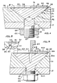
- FIG. 1 Illustrated in Figure 1 is a partial cross-sectional view of the fastener installed in structural elements; the right side of the figure showing the fastener as provided while on the left side the fastener is shown after installation is complete.
- FIG 2 Illustrated in Figure 2 is an enlarged partial cross-sectional view of the fastener shown in Figure 1.
- FIG. 3 Illustrated in Figure 3 is a partial cross-sectional view of a second embodiment of the fastener installed in structural elements; with the right side of the figure showing the fastener as provided while on the left side the fastener is shown after installation is completed.
- Illustrated in Figure 4 is a partial cross-sectional view of a third embodiment of the fastener installed in structural elements; with the right side of the figure showing the fastener in the as provided and the left side of the figure the fastener is shown after installation is completed.
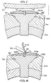
- FIG. 5 Illustrated in Figure 5, 6, 7, and 8 are partial cross-sectional views of the fastener illustrating the process by which the fastener is installed in the structural elements.
- FIG. 1 Illustrated in Figure 1 is a partial cross-sectional view of two structural elements, indicated by numerals 10 and 12, respectively, joined together by the improved flush head fastener, generally indicated by numeral 14.
- the fastener 14 is primarily designed for use on aircraft, and, in particular, to the fastening of external skins or other external structural elements to interior structures.
- structural element 10 can be considered the outer skin of an aircraft having an exterior surface 16 exposed to aerodynamic forces and lightning strikes as well as illumination by threat radars.
- the fastener 14 is shown installed as provided on the right side of the figure and after installation is completed on the left.
- the fastener 14 is mounted in a countersunk fastener hole 18 with the countersunk portion 20 in communication with the surface 16 and having a total included angle indicated by numeral 22 (typically 100 degrees for metals and 130 degrees for composites).
- Fastener 14 includes a head portion 30 having a top surface 32 and a conical shaped underhead surface 34 having a total included angle substantially equal to the angle 22 of the countersink portion 20.
- the fastener further includes a small cylindrical land 36 at the junction of the top and underhead surfaces 32 and 34, respectively. This land 36 is machined to eliminate any sharp edges that would normally exist at the junction of the surfaces 32 and 34. However, this land 36 is extremely small and is shown out of proportion for illustration purposes only.
- a volume indicated by numeral 38 is created between the fastener head and countersink.
- the countersink portion 20 is, typically, larger than the overall diameter of the land 36, thus, the volume 38 is ring shaped. On a contoured surface the volume 38 takes on a more crescent shape.
- the fastener 14 further includes a shank portion 40 having a threaded end 42 with an internal wrenching recess 43 and is held in place by means of a nut and washer, indicated by numerals 44 and 46, respectively.
- a fastener can be locked in place by use of tools applied from the shank end of the fastener.
- a layer of material 50 having a thickness 51 (right side of Figure 1) is joined to the top surface 32 of the fastener 14.
- the fastener is typically high strength heat treated steel or titanium.
- the layer 50 would be made of a soft aluminum or titanium material or a solder such as those covered by Federal Standard QQ-S-571, Tin Alloy, Tin-lead Alloy and Lead Alloy Solders.
- solder is used for the layer of material it can be heated to a very soft, readily deformable state (having a melting point well below that of the aluminum or titanium structural element 10 or the head and shank of the fastener) such that the structural element or fastener are not effected at this temperature.
- the layer of material 50 is deformed so as to fill the volume 38 about the head portion 30 (between the land 36 and countersink portion 20) and, thereafter, the excess material, indicated by dotted lines and numeral 52 on the left side of Figure 1, is removed.
- the remaining material layer 54 and surface 16 are blended into one smooth and continuous surface.
- the overall thickness 51 of the layer of material 50 is therefore selected to provide sufficient material to fill the volume 38 and the remaining unfilled portion of the countersink 20 above the surface 32 of the head portion 30. This thickness will depend upon the allowable (selected) tolerances of the various dimensions of the countersink portion 20 and the head portion 30. The end result is that no discontinuities will exist that could reflect incoming radar signals, the surface is aerodynamically smooth and there are no electrical discontinuities.
- the layer 50 could be a thermoplastic material such as a polycarbonate; one that melts upon heating and does not cure (with a melting point well below the melting point of the matrix-material).
- a thermoplastic material such as a polycarbonate
- Nylon 6 manufactured by the Dupont Corporation, Wilmington, Delaware. In either case the metal fastener is protected from lightning strike attachment.
- the structural element 10 were made of graphite reinforced PEEK (polyetheretherketone) manufactured by ICI, Americas, Inc., Wilmington, Delaware, then the layer of material could be carbon fiber reinforced Nylon 6 to eliminate electrical discontinuities. As can be seen, whether the layer of material is a metal, dielectric material or a dielectric material loaded with conductive fillers will depend upon the particular application.
- FIG 3 Illustrated in Figure 3 is a partial cross-sectional view of a second embodiment of the fastener indicated by numeral 14A.
- the fastener 14A differs only in having an internal wrenching recess 60 in the head 30A and the elimination of the internal wrenching recess 43 (see Figure 1) from the shank 40A. All of the other previously mentioned dimensions of the fastener are identical, and thus, have the same identifying number.
- the layer of material, indicated by numeral 50A, having a thickness 51A incorporates external wrenching surfaces 62 connected by means of a necked down frangible portion 64.
- the nut 44 can be prevented from rotation as the fastener is torqued. However, in most applications the fastener would be engaging a plate nut (not shown).
- FIG 4 Illustrated in Figure 4 is a third embodiment of the fastener.
- the fastener 14B includes a wrenching recess 60B in the head 30B and the layer of material 50B includes an aperture 70 in communication with the recess 60B.
- the fastener 14B can be prevented from rotation when the nut 44 is torqued (or vice versa).
- a plug 71 preferably made of the same material as the layer of material 50B or another suitable material is provided which can be inserted into the recess 60B after the fastener 14B has been locked in place (left side of Figure 4).
- the layer 50B having a thickness indicated by 51B, includes an underhead surface 72 with an included angle 74 equal to angle 22 of the countersink hole and extends upward and outward so as to almost completely fill the countersink (leaving only the small volume 38' between the land 36 and countersink 20). This makes the filling of the countersink by the process to be subsequently discussed much easier.
- the insert or plug is installed (driven in place by a hammer or the like) prior to removing excess layer material 52B, leaving remaining layer 54B. If the fastener needs to be removed, the plug can be "dug out", preferably after heating to soften it.
- the fastener which was illustrated in Figure 4 is used as an example.
- the plug 71 is driven into place as illustrated.
- heat is applied to the material layer 50B and plug 71 until, the materials are soft and easily deformable (as illustrated, a heatlamp 75 is used).
- the layer 50B and plug 71 are tapped down to firmly drive the layer of material 50B into contact with the countersink 20 and filling volume 38'. This step typically deforms the layer of materials 50B so that it has an irregular surface, indicated by numeral 76.
- the structural element 10 is a composite material with an organic matrix
- the layer of the material 50B and plug 71 ideally would be a thermoplastic material, which would require heating to make it deformable.
- the layer of material may be desirable to heat to a temperature wherein it melts and is easily flowable provided the structural elements can withstand the temperature. This would eliminate the need for impact.
- the main advantage of melting is the elimination of any gaps between the fastener head portion and the countersink improving electrical continuity, etc.
- some difficulty may be encountered in removing excess material and providing a smooth surface. Melting could easily be accomplished when using a solder, thermoplastic or even thermosetting materials such as an epoxy.
- the fastener can provide a smooth aerodynamic surface. 2) can provide a surface with no electrical discontinuities. 3) can be used with both metal and composite structures. 4) can provide lightning strike protection.
- Other advantages are a reduced tendency to rotate and loosen, in some applications the tolerances on the countersink end of the hole can be relaxed and it may be possible to eliminate corrosion resistant coatings or sealants on the fastener or hole where such coatings or sealants are presently required.
- the fastener has application on external surfaces of land vehicles and ships, internal fluid ducts in general or on any surface for cosmetic purposes. In this latter application it is apparent that the concept is applicable to fasteners having plastic heads and shanks as long as the plastic has a higher strength and/or higher melting point than the layer of material.
Landscapes
- Engineering & Computer Science (AREA)
- General Engineering & Computer Science (AREA)
- Mechanical Engineering (AREA)
- Aviation & Aerospace Engineering (AREA)
- Connection Of Plates (AREA)
Claims (23)
- Kombination eines Senkkopf-Befestigungselements (14, 14A, 14B) und zweier oder mehrerer, vom Befestigungselement miteinander zu verbindender Strukturelemente (10, 12; 10A, 12A), wobei die Strukturelemente ein Befestigungselementloch (18) mit einer Aussparung (20) in einem der Strukturelemente zum Aufnehmen des Kopfs (30, 30A, 30B) des Befestigungselements in Verbindung mit einer Oberfläche (16) der Strukturelemente aufweisen, wobei das Befestigungselement umfaßt: einen Schaft (40, 40A); einen mit dem Schaft verbundenen Kopf (30, 30A, 30B); und eine Schicht (50, 50A, 50B) aus unelastischem Material, welche dauerhaft mit der gesamten oberen Oberfläche des Kopfs des Befestigungselements verbunden ist und diese im allgemeinen überdeckt, wobei die Größe und Gestalt des Kopfs und der Materialschicht im Vergleich mit der Größe und Gestalt der Aussparung derart sind, daß bei anfänglichem Einbau des Befestigungselements in das Loch ein Spalt zwischen dem Kopf, der Materialschicht und der Aussparung vorhanden ist, wobei die Materialschicht relativ zu dem Kopf und den Strukturelementen ohne weiteres rekonfigurierbar ist, derart, daß auf den anfänglichen Einbau des Befestigungselements in das Loch folgend die Materialschicht durch Verformung zum Füllen des Spalts umformbar ist und das überschüssige, über das zum Einpassen der Materialschicht in wesentliche Konformität mit der einen Oberfläche der Strukturelemente hinaus erforderliche Material ohne weiteres entfernbar ist.
- Kombination nach Anspruch 1, bei welcher der Schmelzpunkt der Materialschicht (50, 50A, 50B) wesentlich niedriger ist als der Schmelzpunkt des Kopfs (30, 30A, 30B) und des Schafts (40, 40A) des Befestigungselements und der Strukturelemente, so daß die Materialschicht nach Einbau auf eine Temperatur bringbar ist, bei der ihre rekonfigurierbaren Eigenschaften verstärkt sind.
- Kombination nach Anspruch 2, bei welcher die Aussparung (20) eine Senkung ist.
- Kombination nach Anspruch 3, bei welcher die Senkung (20) konusförmig ist und einen bestimmten Gesamtöffnungswinkel (22) aufweist, wobei das Befestigungselement ferner umfaßt: den Kopf mit einem konusförmigen Unterkopf (34), welcher einen Gesamtöffnungswinkel aufweist, welcher im allgemeinen gleich dem Gesamtöffnungswinkel des Senkungslochs ist; und die sich nach außen und oben von der oberen Oberfläche des Kopfs erstreckende Materialschicht (50, 50A, 50B), wobei die Materialschicht einen konusförmigen Unterkopf aufweist, welcher an die konische Unterseite des Kopfs angrenzt und zu dieser ausgerichtet ist und einen Gesamtöffnungswinkel aufweist, welcher im allgemeinen gleich demjenigen der konischen Unterseite des Kopfs ist.
- Kombination nach Anspruch 4, bei welcher die Materialschicht (50, 50A, 50B) ein leitendes Material ist.
- Kombination nach Anspruch 5, bei welcher die Materialschicht (50, 50A, 50B) ein Metall ist.
- Kombination nach Anspruch 5, bei welcher die Materialschicht (50, 50A, 50B) ein mit leitenden Füllstoffen beladenes dielektrisches Material ist.
- Kombination nach Anspruch 4, bei welcher die Materialschicht (50, 50A, 50B) ein dielektrisches Material ist.
- Kombination nach Anspruch 4, bei welcher die Materialschicht (50, 50A, 50B) aus der Gruppe ausgewählt ist, welche thermoplastische und wärmehärtbare Materialien umfaßt.
- Kombination nach Anspruch 1, 2, 3, 4, 5, 6, 7, 8 oder 9, bei welcher zerbrechbare äußere Verdrehungsflächen (62) an der Oberseite der Materialschicht (50A) angebracht sind.
- Kombination nach Anspruch 1, 2, 3, 4, 5, 6, 7, 8 oder 9, bei welcher der Kopf eine innere Verdrehungsaussparung (60B) umfaßt; wobei die Materialschicht (50B) ein hindurchgehendes Verdrehungswerkzeugzugangsloch (70) umfaßt, welches mit der inneren Verdrehungsaussparung in Verbindung steht; und einen Stöpsel (71), welcher aus kompatiblem Material zum Füllen der Aussparung in dem Kopf und des Lochs in der Materialschicht gebildet ist.
- Kombination nach Anspruch 11, bei welcher der Stöpsel (71) aus Material gebildet ist, welches im allgemeinen identisch mit der Materialschicht ist.
- Verfahren zum Verbinden zweier oder mehrerer Strukturelemente (10, 12; 10A, 12A), welches folgende Schritte umfaßt: Bilden eines Befestigungselementsenkungslochs (20) in den Strukturelementen, wobei die Senkung an einer Außenfläche (16) eines (10, 10A) der Strukturelemente angeordnet ist; Vorsehen eines Befestigungselements (14, 14A, 14B) mit einem Schaftabschnitt (40, 40A) und einem Kopfabschnitt (30, 30A, 30B) und einer Schicht (50, 50A, 50B) aus unelastischem Material, welche dauerhaft mit der oberen Oberfläche des Kopfs (30, 30A, 30B) verbunden ist, wobei die Materialschicht relativ zu dem Kopf und dem Schaft und den Strukturelementen ohne weiteres rekonfigurierbar ist; Positionieren des Befestigungselements (14, 14A, 14B) in dem Loch, wobei der Kopf des Befestigungselements in Kontakt mit der Senkung ist; Verformen der Materialschicht (50, 50A, 50B), derart, daß jeder Spalt zwischen der Senkung und dem Kopf gefüllt wird; und Entfernen von überschüssigem Material (52, 52A, 52B) der Materialschicht, derart, daß die obere Oberfläche der verformten Materialschicht stetig mit der an das Befestigungselement angrenzenden Außenfläche ist.
- Verfahren nach Anspruch 13, bei welchem die Senkung (20) konusförmig ist und einen bestimmten Gesamtöffnungswinkel (22) aufweist, wobei der Kopf einen konusförmigen Unterkopf mit einem Gesamtöffnungswinkel aufweist, welcher im allgemeinen gleich dem Gesamtöffnungswinkel des Senkungslochs ist; und sich die Materialschicht von der oberen Oberfläche des Kopfs nach außen und oben erstreckt, wobei die Materialschicht einen konusförmigen Unterkopf aufweist, der stetig mit der konusförmigen Unterseite des Kopfs ist und einen Gesamtöffnungswinkel aufweist, welcher im allgemeinen gleich demjenigen der konischen Unterseite des Kopfs ist.
- Verfahren nach Anspruch 13 oder 14, bei welchem vor dem Schritt des Verformens der Materialschicht die Materialschicht auf eine Temperatur erwärmt wird, bei der sie ohne weiteres rekonfigurierbar ist.
- Verfahren nach Anspruch 15, bei welchem während des Erwärmungsschritts die Materialschicht auf einen Punkt erwärmt wird, bei der sie schmilzt.
- Verfahren nach einem der Ansprüche 13 bis 16, bei welchem das Befestigungselement (14A) zerbrechbare, äußere Verdrehungsflächen (62) umfaßt, welche an der Oberseite der Materialschicht (50A) angebracht sind, wobei das Verfahren den zusätzlichen Schritt des Abbrechens der zerbrechbaren, äußeren Verdrehungsflächen vor dem Schritt des Verformens der Materialschicht umfaßt.
- Verfahren nach einem der Ansprüche 13 bis 16, bei welchem der Kopf des Befestigungselements (14B) eine innere Verdrehungsaussparung (60B) umfaßt und die Materialschicht (50B) ein hindurchgehendes Verdrehungswerkzeugzugangsloch (70) umfaßt, welches in Verbindung mit der inneren Verdrehungsaussparung steht, wobei das Verfahren ferner vor dem Schritt des Verformens der Materialschicht die Schritte des Vorsehens eines aus einem im allgemeinen mit der Materialschicht identischen Material gebildeten Stöpsels (71) zum Füllen der Aussparung in dem Kopf und des Lochs in der Materialschicht und des Einbauens des Stöpsels in das Loch und die Aussparung umfaßt.
- Verfahren nach einem der Ansprüche 13 bis 18, bei welchem die Materialschicht ein leitendes Material ist.
- Verfahren nach Anspruch 19, bei welchem die Materialschicht ein Metall ist.
- Verfahren nach Anspruch 19, bei welchem die Materialschicht ein mit leitenden Füllstoffen beladenes dielektrisches Material ist.
- Verfahren nach einem der Ansprüche 13 bis 18, bei welchem die Materialschicht ein dielektrisches Material ist.
- Verfahren nach Anspruch 22, bei welchem die Materialschicht aus der Gruppe ausgewählt ist, welche thermoplastische und wärmehärtbare Harze umfaßt.
Applications Claiming Priority (2)
| Application Number | Priority Date | Filing Date | Title |
|---|---|---|---|
| US07/135,852 US4884929A (en) | 1987-12-21 | 1987-12-21 | Flush head fastener |
| PCT/US1989/002432 WO1990015259A1 (en) | 1987-12-21 | 1989-06-05 | Improvement to flush head fastener |
Publications (3)
| Publication Number | Publication Date |
|---|---|
| EP0432164A1 EP0432164A1 (de) | 1991-06-19 |
| EP0432164A4 EP0432164A4 (en) | 1992-01-08 |
| EP0432164B1 true EP0432164B1 (de) | 1995-03-01 |
Family
ID=22470014
Family Applications (1)
| Application Number | Title | Priority Date | Filing Date |
|---|---|---|---|
| EP89907500A Expired - Lifetime EP0432164B1 (de) | 1987-12-21 | 1989-06-05 | Senkkopf-befestigungselement |
Country Status (6)
| Country | Link |
|---|---|
| US (1) | US4884929A (de) |
| EP (1) | EP0432164B1 (de) |
| JP (1) | JPH03502357A (de) |
| DE (1) | DE68921484T2 (de) |
| IL (1) | IL88670A0 (de) |
| WO (1) | WO1990015259A1 (de) |
Cited By (1)
| Publication number | Priority date | Publication date | Assignee | Title |
|---|---|---|---|---|
| US20130316120A1 (en) * | 2012-05-23 | 2013-11-28 | The Boeing Company | Method of filling voids around countersunk fastener heads |
Families Citing this family (28)
| Publication number | Priority date | Publication date | Assignee | Title |
|---|---|---|---|---|
| US5391028A (en) * | 1993-05-12 | 1995-02-21 | Northrop Grumman Corporation | Method for reducing radar cross-section of aircraft fasteners, and fastener assemblies for use therein |
| US6315485B1 (en) | 1999-08-13 | 2001-11-13 | Northrop Grumman Corporation | Low observable aircraft fastener treatment |
| US6302630B1 (en) * | 2000-04-18 | 2001-10-16 | Lockheed Martin | Fastener with recessed head and head insert |
| US6679667B2 (en) * | 2001-02-28 | 2004-01-20 | Northrop Grumman Corporation | Hot melt fastener filler |
| US6899502B2 (en) * | 2003-06-30 | 2005-05-31 | Khameleon Nails, Inc. | Self-filling fastener and method of making |
| US20050147485A1 (en) * | 2003-06-30 | 2005-07-07 | Strunk Jeffrey L. | Self-filling fastener and method of making |
| US7997220B1 (en) * | 2004-05-28 | 2011-08-16 | Robert Wayne Beal | Marine vessel module |
| JP4550052B2 (ja) * | 2004-06-10 | 2010-09-22 | 日本電信電話株式会社 | ネジ |
| US20060099843A1 (en) * | 2004-11-01 | 2006-05-11 | Fullner Todd C | Dielectric fittings |
| JP4786426B2 (ja) * | 2005-10-06 | 2011-10-05 | 三菱重工業株式会社 | ファスナ |
| US20070212190A1 (en) * | 2006-01-20 | 2007-09-13 | Monday John S | Low profile fastening system |
| WO2007107977A2 (en) * | 2006-02-02 | 2007-09-27 | Safecar Theft Prevention Systems Ltd. | Vehicle anti-theft device |
| US20080003078A1 (en) | 2006-05-02 | 2008-01-03 | United Technologies Corporation | Fastener |
| US9086085B2 (en) * | 2006-07-26 | 2015-07-21 | The Boeing Company | Removeable fastener recess insert and method for making same |
| JP2008285115A (ja) | 2007-05-21 | 2008-11-27 | Mitsubishi Heavy Ind Ltd | 航空機組立品およびその製造方法 |
| JP4719203B2 (ja) * | 2007-09-28 | 2011-07-06 | 三菱重工業株式会社 | 耐雷ファスナ |
| US7721996B2 (en) * | 2007-11-13 | 2010-05-25 | The Boeing Company | Fabrication and installation of preformed dielectric inserts for lightning strike protection |
| ES2376323B1 (es) * | 2009-02-27 | 2013-01-24 | Airbus Operations, S.L. | Mejora de la protección contra impacto directo de rayos en zonas remachadas de paneles en cfrp. |
| JP5517538B2 (ja) * | 2009-09-25 | 2014-06-11 | 三菱航空機株式会社 | 耐雷ファスナ、航空機組立品 |
| DE102010040338A1 (de) * | 2010-09-07 | 2012-03-08 | Airbus Operations Gmbh | Befestigungselement für blitzschlaggefährdete Bauteile |
| DE102010040337A1 (de) * | 2010-09-07 | 2012-03-08 | Airbus Operations Gmbh | Niet und Verfahren zur Herstellung einer Nietverbindung |
| JP5479383B2 (ja) * | 2011-02-14 | 2014-04-23 | 三菱重工業株式会社 | 航空機組立品 |
| JP5535956B2 (ja) * | 2011-02-14 | 2014-07-02 | 三菱重工業株式会社 | 耐雷ファスナ |
| US8950961B2 (en) | 2011-06-13 | 2015-02-10 | Lockheed Martin Corporation | Methods and apparatus for applying filler material onto an object |
| US11058469B2 (en) * | 2013-12-13 | 2021-07-13 | The University Of Akron | Minimal shock set screw |
| DE102014222879A1 (de) * | 2014-11-10 | 2016-05-25 | Tyco Electronics Raychem Gmbh | Abdeckelement für einen elektrischen Verbinder |
| US9748699B1 (en) * | 2015-05-19 | 2017-08-29 | Amazon Technologies, Inc. | Screw boss assemblies and methods |
| DE102017222185A1 (de) | 2017-12-07 | 2019-06-13 | Premium Aerotec Gmbh | Sondenbefestigungssystem und Luftfahrzeug |
Citations (1)
| Publication number | Priority date | Publication date | Assignee | Title |
|---|---|---|---|---|
| US4479163A (en) * | 1982-09-30 | 1984-10-23 | The Boeing Company | Integral lightning protection system for composite aircraft skins |
Family Cites Families (10)
| Publication number | Priority date | Publication date | Assignee | Title |
|---|---|---|---|---|
| US49163A (en) * | 1865-08-01 | Improvement in key-bolt conn ections for car-trucks | ||
| US1145256A (en) * | 1914-01-27 | 1915-07-06 | Carl H L Mochow | Bolt-lock. |
| GB684821A (en) * | 1950-04-22 | 1952-12-24 | Svenska Aeroplan Ab | Improvements in and relating to fastening elements such as rivets, bolts, screws or the like |
| US3065662A (en) * | 1959-08-28 | 1962-11-27 | Voi Shan Ind Inc | Plug means for countersunk fasteners having recessed heads |
| US3812757A (en) * | 1969-11-04 | 1974-05-28 | Textron Inc | Threaded fastener with torque control head |
| AT355880B (de) * | 1978-05-24 | 1980-03-25 | Semperit Ag | Schraubenabdeckung |
| US4502092A (en) * | 1982-09-30 | 1985-02-26 | The Boeing Company | Integral lightning protection system for composite aircraft skins |
| US4681497A (en) * | 1985-05-29 | 1987-07-21 | Microdot Inc. | Encapsulated fastener |
| US4628402A (en) * | 1985-09-30 | 1986-12-09 | The Boeing Company | Lightning protection of fasteners in composite material |
| US4630168A (en) * | 1985-12-16 | 1986-12-16 | The Boeing Company | Lightning protection fastener |
-
1987
- 1987-12-21 US US07/135,852 patent/US4884929A/en not_active Expired - Lifetime
-
1988
- 1988-12-13 IL IL88670A patent/IL88670A0/xx unknown
-
1989
- 1989-06-05 WO PCT/US1989/002432 patent/WO1990015259A1/en not_active Ceased
- 1989-06-05 JP JP1506873A patent/JPH03502357A/ja active Granted
- 1989-06-05 DE DE68921484T patent/DE68921484T2/de not_active Expired - Fee Related
- 1989-06-05 EP EP89907500A patent/EP0432164B1/de not_active Expired - Lifetime
Patent Citations (1)
| Publication number | Priority date | Publication date | Assignee | Title |
|---|---|---|---|---|
| US4479163A (en) * | 1982-09-30 | 1984-10-23 | The Boeing Company | Integral lightning protection system for composite aircraft skins |
Cited By (2)
| Publication number | Priority date | Publication date | Assignee | Title |
|---|---|---|---|---|
| US20130316120A1 (en) * | 2012-05-23 | 2013-11-28 | The Boeing Company | Method of filling voids around countersunk fastener heads |
| US9481012B2 (en) * | 2012-05-23 | 2016-11-01 | The Boeing Company | Method of filling voids around countersunk fastener heads |
Also Published As
| Publication number | Publication date |
|---|---|
| JPH0577884B2 (de) | 1993-10-27 |
| JPH03502357A (ja) | 1991-05-30 |
| DE68921484T2 (de) | 1995-06-29 |
| US4884929A (en) | 1989-12-05 |
| EP0432164A4 (en) | 1992-01-08 |
| WO1990015259A1 (en) | 1990-12-13 |
| IL88670A0 (en) | 1989-07-31 |
| EP0432164A1 (de) | 1991-06-19 |
| DE68921484D1 (de) | 1995-04-06 |
Similar Documents
| Publication | Publication Date | Title |
|---|---|---|
| US4884929A (en) | Flush head fastener | |
| US4979281A (en) | Method of installing a flush head fastener | |
| EP0226229B1 (de) | Blitzschlagschutz-Befestigungsteil | |
| EP2830948B1 (de) | Befestigungssysteme für eme-schutz | |
| EP2256030B1 (de) | Flugzeugbaugruppe | |
| US8882423B2 (en) | Lightning-resistant fastener and mounting structure of lightning-resistant fastener | |
| US9611052B2 (en) | Fastener systems that provide EME protection | |
| EP2500273A2 (de) | Blitzschutzhalterung, Flugzeuganordnung und Verfahren zur Herstellung der Flugzeuganordnungskomponente | |
| EP2871132B1 (de) | Befestigungssysteme für EME-Schutz | |
| US9669942B2 (en) | Lightning damage resistant aircraft skin fasteners | |
| EP3249242B1 (de) | Befestigungsstruktur für kohlenstofffaserverstärktes harzmaterial | |
| CN113153882B (zh) | 用于导电涂覆紧固系统的装置和方法 | |
| EP2147855A1 (de) | Flugzeuganordnung und verfahren zu ihrer herstellung | |
| EP3070347A1 (de) | Selbstabdichtendes befestigungselement | |
| EP4071047B1 (de) | Vorrichtung und verfahren zum blitzschutz und zur lokalisierung von befestigungsmuttern mit dielektrischen materialien | |
| WO2013117756A1 (en) | Connecting arrangement and method for providing such connecting arrangement | |
| US20200217349A1 (en) | Conductive fastening system and method for improved eme performance | |
| CN108488192A (zh) | 一种轴型铆接螺母及其制作方法 | |
| US11447230B2 (en) | Aircraft fuel tank access panel assemblies | |
| US12031564B2 (en) | Spark containment cap | |
| CA1308581C (en) | Flush head fastener | |
| EP4001124B1 (de) | Dichtungsabdeckungsanordnung für ein flugzeug oder eine andere struktur und montageverfahren dafür | |
| US20250263178A1 (en) | Assembly of aircraft wings |
Legal Events
| Date | Code | Title | Description |
|---|---|---|---|
| PUAI | Public reference made under article 153(3) epc to a published international application that has entered the european phase |
Free format text: ORIGINAL CODE: 0009012 |
|
| 17P | Request for examination filed |
Effective date: 19910123 |
|
| AK | Designated contracting states |
Kind code of ref document: A1 Designated state(s): DE FR GB |
|
| A4 | Supplementary search report drawn up and despatched |
Effective date: 19911115 |
|
| AK | Designated contracting states |
Kind code of ref document: A4 Designated state(s): DE FR GB |
|
| 17Q | First examination report despatched |
Effective date: 19920803 |
|
| GRAA | (expected) grant |
Free format text: ORIGINAL CODE: 0009210 |
|
| AK | Designated contracting states |
Kind code of ref document: B1 Designated state(s): DE FR GB |
|
| REF | Corresponds to: |
Ref document number: 68921484 Country of ref document: DE Date of ref document: 19950406 |
|
| PG25 | Lapsed in a contracting state [announced via postgrant information from national office to epo] |
Ref country code: GB Effective date: 19950605 |
|
| ET | Fr: translation filed | ||
| PLBE | No opposition filed within time limit |
Free format text: ORIGINAL CODE: 0009261 |
|
| STAA | Information on the status of an ep patent application or granted ep patent |
Free format text: STATUS: NO OPPOSITION FILED WITHIN TIME LIMIT |
|
| GBPC | Gb: european patent ceased through non-payment of renewal fee |
Effective date: 19950605 |
|
| 26N | No opposition filed | ||
| PG25 | Lapsed in a contracting state [announced via postgrant information from national office to epo] |
Ref country code: FR Effective date: 19960229 |
|
| PG25 | Lapsed in a contracting state [announced via postgrant information from national office to epo] |
Ref country code: DE Effective date: 19960301 |
|
| REG | Reference to a national code |
Ref country code: FR Ref legal event code: ST |