EP0432207B1 - Appareil de sechage par pulverisation - Google Patents
Appareil de sechage par pulverisation Download PDFInfo
- Publication number
- EP0432207B1 EP0432207B1 EP89910075A EP89910075A EP0432207B1 EP 0432207 B1 EP0432207 B1 EP 0432207B1 EP 89910075 A EP89910075 A EP 89910075A EP 89910075 A EP89910075 A EP 89910075A EP 0432207 B1 EP0432207 B1 EP 0432207B1
- Authority
- EP
- European Patent Office
- Prior art keywords
- drying
- devices
- drying tower
- conveyor belt
- gas
- Prior art date
- Legal status (The legal status is an assumption and is not a legal conclusion. Google has not performed a legal analysis and makes no representation as to the accuracy of the status listed.)
- Expired - Lifetime
Links
- 238000001694 spray drying Methods 0.000 title claims abstract description 5
- 238000001035 drying Methods 0.000 claims abstract description 67
- 239000002245 particle Substances 0.000 claims abstract description 28
- 238000010276 construction Methods 0.000 claims abstract description 17
- 239000000463 material Substances 0.000 claims abstract description 10
- 238000009826 distribution Methods 0.000 claims abstract description 9
- 239000007788 liquid Substances 0.000 claims abstract description 9
- 239000011343 solid material Substances 0.000 claims abstract description 5
- 239000007787 solid Substances 0.000 claims abstract description 3
- 238000007664 blowing Methods 0.000 claims description 8
- 230000007704 transition Effects 0.000 claims description 4
- 239000007789 gas Substances 0.000 description 24
- 239000000654 additive Substances 0.000 description 2
- 230000003247 decreasing effect Effects 0.000 description 2
- 238000000034 method Methods 0.000 description 2
- 238000005192 partition Methods 0.000 description 2
- 230000035515 penetration Effects 0.000 description 2
- 239000000843 powder Substances 0.000 description 2
- 239000000126 substance Substances 0.000 description 2
- 230000002745 absorbent Effects 0.000 description 1
- 239000002250 absorbent Substances 0.000 description 1
- 230000015572 biosynthetic process Effects 0.000 description 1
- 230000000903 blocking effect Effects 0.000 description 1
- 239000000112 cooling gas Substances 0.000 description 1
- 239000003814 drug Substances 0.000 description 1
- 230000000694 effects Effects 0.000 description 1
- 238000005507 spraying Methods 0.000 description 1
- 239000000725 suspension Substances 0.000 description 1
- 238000009827 uniform distribution Methods 0.000 description 1
Images



Classifications
-
- F—MECHANICAL ENGINEERING; LIGHTING; HEATING; WEAPONS; BLASTING
- F26—DRYING
- F26B—DRYING SOLID MATERIALS OR OBJECTS BY REMOVING LIQUID THEREFROM
- F26B5/00—Drying solid materials or objects by processes not involving the application of heat
- F26B5/12—Drying solid materials or objects by processes not involving the application of heat by suction
-
- B—PERFORMING OPERATIONS; TRANSPORTING
- B01—PHYSICAL OR CHEMICAL PROCESSES OR APPARATUS IN GENERAL
- B01D—SEPARATION
- B01D1/00—Evaporating
- B01D1/16—Evaporating by spraying
- B01D1/18—Evaporating by spraying to obtain dry solids
-
- F—MECHANICAL ENGINEERING; LIGHTING; HEATING; WEAPONS; BLASTING
- F26—DRYING
- F26B—DRYING SOLID MATERIALS OR OBJECTS BY REMOVING LIQUID THEREFROM
- F26B3/00—Drying solid materials or objects by processes involving the application of heat
- F26B3/02—Drying solid materials or objects by processes involving the application of heat by convection, i.e. heat being conveyed from a heat source to the materials or objects to be dried by a gas or vapour, e.g. air
- F26B3/10—Drying solid materials or objects by processes involving the application of heat by convection, i.e. heat being conveyed from a heat source to the materials or objects to be dried by a gas or vapour, e.g. air the gas or vapour carrying the materials or objects to be dried with it
- F26B3/12—Drying solid materials or objects by processes involving the application of heat by convection, i.e. heat being conveyed from a heat source to the materials or objects to be dried by a gas or vapour, e.g. air the gas or vapour carrying the materials or objects to be dried with it in the form of a spray, i.e. sprayed or dispersed emulsions or suspensions
-
- Y—GENERAL TAGGING OF NEW TECHNOLOGICAL DEVELOPMENTS; GENERAL TAGGING OF CROSS-SECTIONAL TECHNOLOGIES SPANNING OVER SEVERAL SECTIONS OF THE IPC; TECHNICAL SUBJECTS COVERED BY FORMER USPC CROSS-REFERENCE ART COLLECTIONS [XRACs] AND DIGESTS
- Y10—TECHNICAL SUBJECTS COVERED BY FORMER USPC
- Y10S—TECHNICAL SUBJECTS COVERED BY FORMER USPC CROSS-REFERENCE ART COLLECTIONS [XRACs] AND DIGESTS
- Y10S159/00—Concentrating evaporators
- Y10S159/16—Vacuum
Definitions
- the present invention relates to a spray drying apparatus for drying liquids containing solid materials in soluble or suspended form.
- US patent specifications Nos. 3,615,723 and 3,741,273 disclose a spray drying apparatus comprising a drying tower, atomizing devices placed in the upper part of the drying chamber for comminuting the liquid to be dried into droplets, devices for introducing heated drying gas into the upper part of the drying chamber directed towards the droplets, a movable perforated surface placed under the lower end of the drying tower for collecting partially dried particles of solid material, devices for sucking gas together with suspended partially dried solid particles from the drying tower through the movable perforated surface while the particles or a substantial part of the particles settle on the movable perforated surface as an agglomerated porous layer of material, and devices for finish drying the agglomerated porous layer of material while the perforated surface is moved forwards.
- the atomizing devices may comprise a number of downwardly directed nozzles for forming liquid droplets which together with a laminar stream of drying gas are conducted down through the chamber.
- a rotary disc may instead be used for atomizing the liquid.
- the drying gas may also be used as a turbulent gas stream passing downwards or circulating in the chamber. The partially dried particles will agglomerate and settle as a layer on the movable perforated surface which can be a conveyor belt made of wire netting or woven filter mat.
- a drying apparatus of this kind is suitable for drying sensitive and easily decomposable materials, such as foodstuffs and pharmaceuticals since the drying temperature is low.
- the layer of particles on the conveyor belt may advantageously be formed as a stable product with an open structure and an even thickness in the transverse direction, which necessitates an even distribution of the particles when settling.
- This is an aim which is hard to achieve, especially when using large or cylindrical drying chambers, in which case the layer in principle (when using a laminar gas stream) will be thickest in the middle with a decreasing thickness towards the edge of the conveyor belt, even if the belt covers the entire bottom of the chamber.
- the layer in principle when using a laminar gas stream
- the layer in principle when using a laminar gas stream
- the layer in principle when using a laminar gas stream
- the layer in principle when using a laminar gas stream
- the layer in principle when using a laminar gas stream
- the layer in principle when using a laminar gas stream
- the layer in principle when using a laminar gas stream
- the layer in principle when using a laminar gas stream
- the layer in principle when using a lamin
- the apparatus comprises a drying tower, the lower part of which is equipped with or connected to a bustle chamber comprising devices for controlling the amount and/or the distribution of gas sucked thorugh the perforated surface.
- the surface is perferably continuously or intermittently movable long the bottom of the drying tower.
- the perforated surface can also be made of wire netting or filter mat covering the bottom of the drying tower. During operation, the net or the filter mat may move when the layer of agglomerated particles has reached the desired thickness.
- the apparatus can instead be equipped with devices for intermittent removal of the powder settled on the net or filter mat.
- the tower is preferably an elongated downwardly open cylinder.
- the bustle construction comprises a shell surrounding the lower end of the drying tower and being connected to the tower, the chamber being connected to suction devices for removing a fraction of the drying gas from the lower end of the drying tower and possibly also being provided with blowing devices for introducing a gas into the lower end of the tower at certain locations.
- blowing in secondary gas through openings in the chamber wall it is further possible to achieve a desired control of the wall temperature on the inner side of the chamber wall, which entails significant advantages when drying temperature sensitive products, absorbent products, or when drying is performed under conditions close to dew point.
- the amount of blown in gas can in certain process situations constitute a minor amount of the total amount of drying air and can be contained in the amount of air being sucked out through the shell space, while in other situations it may entail an excess of air which is partly sucked out through the perforated surface under the product mat.
- Secondary gas may also be introduced into the chamber from above, e.g. through concentric ducts.
- the devices for controlling the amount and/or distribution of the gas sucked through the movable perforated surface normally only consist of suction devices, it is sometimes appropriate at certain locations also to add blowing devices, if suitable for balancing the pressure difference between the two sides of the movable perforated surface and possibly for removing particles from the said locations.
- the devices for controlling the amount and/or distribution of the gas which later is to be sucked through the movable perforated surface comprise several minor openings placed at the circumference of the bustle chamber and connected to individually adjustable suction and/or blowing devices.
- the individual adjustment of the air stream at different locations makes it possible to ensure a very even thickness of the layer of particles on the conveyor belt.
- the bustle construction may advantageously be a transition unit, the lower end of which having a rectangular cross-section adjacent to the conveyor belt and substantially the same width as the conveyor belt.
- the bustle construction is connected to a chamber surrounding the conveyor belt and comprising several compartments placed under the belt, each compartment having means for individual adjustment of the pressure difference over the section in question of the conveyor belt.
- This arrangement serves the purpose of further ensuring an even thickness in the transverse direction of the layer of particles settled on the conveyor belt.
- the apparatus shown in fig. 1 comprises a vertical cylindrical drying chamber 1, atomizing devices 2, placed in the upper part of the drying tower, inlet tubes 3,3 for heated drying gas.
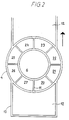
- the bustle construction 4 surrounds the lower end of the drying tower.
- the interior 5 of the bustle chamber communicates with the interior 6 of the lower end of the drying tower.
- the drying air with suspended droplets passes downwards, illustrated by arrows 7. Air from the bustle construction 4 is sucked out through 8,8, the stream being adjusted by means of valves 9,9 so that a part of the drying gas passes from the lower end of the drying chamber into the bustle construction in the direction of the arrows 10,10 and out through the tubes 8,8.
- the entire conveyor belt 12 is contained in the chamber 13, and a number of compartments 14, 15, 16 connected to individually adjustable suction devices 17, 18, 19, is placed in the chamber 13 under the conveyor belt 12.
- the interior of the bustle chamber is divided into several compartments 20, 21, 22, 23, 24, 25, 26 and 27, as better seen in fig. 2, the compartments being separated by partition walls 11.
- the conveyor belt 12 passes through two compartments 30, 31, connected to suction devices 32, 33 and to inlet tubes for supplementary drying gas.
- the agglomerated layer 36 of particles is finish dried in these compartments.
- the conveyor belt with the dried layer of particles passes through another chamber 37 to which are connected suction devices 38 and an inlet tube 39 for cooling gas.
- the layer of dried particles is disintegrated at the end of the conveyor belt and collected through a funnel-shaped outlet opening 40.
- Fig. 3 shows a section of a bustle construction formed as a transition unit with a rectangular cross-section 41 connected to the conveyor belt 12.
- the bustle construction is divided into several compartments 42, 43, 44, 45, 46, 47, 48, 49, 50, 51, 52 and 53, being connected to devices (not shown) for individual control of the pressure in each compartment.
- Secondary air containing gaseous, liquid or powdery materials or additives, such as aroma substances or anti-caking substances, etc., may through one or more of the compartments be added to the material on the belt.
- Gaseous additives may also be added through one or more of the compartments 14, 15 under the conveyor belt.
- the bustle construction shown in fig. 4 comprises a shell 411 surrounding the lower part of a drying chamber 406.
- the wall 401 of the drying chamber is provided with a number of openings 420, 421, 322, 423 through which secondary gas can be introduced into the chamber 406 in the direction of the arrows 430, 431, 432, 433 from the shell 411.
- secondary drying gas can be introduced, which prevents settlement of dried particles along the chamber wall and at the same time ensures a more even distribution of the dried particles which settle on a perforated bottom 436, which may be stationary or a movable conveyor belt.
- FIG. 5 A similar effect can be achieved by the embodiment shown in fig. 5.
- the figure is a cross-section of the upper part of a spraying plant comprising a chamber 501 with a chamber wall 502. A number of cylindrical partition walls project from above to form ducts 505, 506, 507, ending at different hights in the chamber.
- An atomizing unit 503 with an atomizing disc is placed centrally at the top of the chamber.
- the gas flow for drying air is shown by the arrow 504.
- Varying amounts of secondary drying air, shown by the arrows 508, 509, 510, can be introduced through the ducts 505, 506, 507. By controlling the amounts of drying air in the ducts it is possible to achieve a better distribution of the dried material and prevent material from settling along the chamber wall.
Landscapes
- Engineering & Computer Science (AREA)
- Life Sciences & Earth Sciences (AREA)
- Mechanical Engineering (AREA)
- General Engineering & Computer Science (AREA)
- Health & Medical Sciences (AREA)
- Molecular Biology (AREA)
- Microbiology (AREA)
- Chemical & Material Sciences (AREA)
- Chemical Kinetics & Catalysis (AREA)
- Drying Of Solid Materials (AREA)
- Vaporization, Distillation, Condensation, Sublimation, And Cold Traps (AREA)
Abstract
Claims (6)
- Appareil de séchage par pulvérisation pour sécher des liquides contenant des matériaux solides sous forme dissoute ou en suspension, comprenant:- une tour de séchage (1) ayant une ouverture (6) à son extrémité inférieure,- des moyens d'atomisation (2) placés dans la partie supérieure de la tour de séchage pour pulvériser le liquide à sécher en gouttelettes,- des moyens (3) pour introduire un gaz de séchage chauffé dans la partie supérieure de la tour de séchage en direction des gouttelettes,- une surface perforée amovible (12) placée sous l'ouverture à l'extrémité inférieure de la tour de séchage pour récupérer les particules partiellement séchées de matériau solide,- des moyens (17, 18, 19) pour aspirer l'air avec des particules solides en suspension partiellement séchées, de la tour de séchage à travers la surface perforée, tandis que les particules ou une partie substantielle des particules se déposent sur la surface perforée sous forme de couche poreuse agglomérée de matériau, et- des moyens (32, 33, 38) pour finir de sécher la couche poreuse agglomérée de matériaucaractérisée en ce que la partie inférieure de la tour de séchage (1) est équipée de ou reliée à une chambre d'agitation comprenant une chambre (11), entourant l'extrémité inférieure de la tour de séchage (1) et communiquant avec la tour, ladite chambre d'agitation étant reliée à des moyens d'aspiration (17, 18, 19) pour éliminer une partie du gaz de séchage de l'extrémité inférieure de la tour de séchage (1) et -si besoin est- également avec des moyens de soufflage (420, 421, 422, 423) pour introduire un gaz dans l'extrémité inférieure de la tour à certains endroits, les moyens d'aspiration (17, 18, 19) et les moyens de soufflage (420, 421, 422, 423) étants ajustables individuellement.
- Appareil selon la revendication 1, caractérisé en ce que la tour de séchage est un cylindre ouvert vers le bas et allongé.
- Appareil selon la revendication 1, caractérisé en ce que les moyens (17, 18, 19) pour réguler la quantité et la distribution du gaz à aspirer à travers la surface perforée amovible comprend plusieurs ouvertures mineures (20-27) placées à la circonférence de la chambre d'agitation.
- Appareil selon la revendication 1, dans laquelle la surface perforée amovible est une bande transporteuse (12) caractérisée en ce que la chambre d'agitation comprend une unité de transition, dont l'extrémité inférieure présente une section transversale rectangulaire adjacente à la bande transporteuse (12) et essentiellement la même largeur que la bande transporteuse.
- Appareil selon la revendication 4, caractérisé en ce que les ouvertures sur les deux côtés à angle droit dans la direction du mouvement de la bande transporteuse (12) sont réunies à des moyens d'aspiration (17, 18, 19), et en ce que les ouvertures ou au moins quelques unes des ouvertures sur les deux côtés parallèles à la direction du mouvement sont reliées aux moyens de soufflage (420, 421, 422, 423).
- Appareil selon la revendication 4, caractérisé en ce que la chambre d'agitation est reliée à une chambre (13) entourant la bande transporteuse, et comprenant plusieurs compartiments (14, 15, 16) placés sous la bande transporteuse (12), chaque compartiment étant équipé de moyens pour l'ajustement individuel de la différence de pression sur la section adjacente de la bande transporteuse.
Priority Applications (1)
| Application Number | Priority Date | Filing Date | Title |
|---|---|---|---|
| AT89910075T ATE99406T1 (de) | 1988-09-02 | 1989-09-01 | Spritztrocknungsvorrichtung. |
Applications Claiming Priority (2)
| Application Number | Priority Date | Filing Date | Title |
|---|---|---|---|
| DK489688A DK489688D0 (da) | 1988-09-02 | 1988-09-02 | Forstoevningstoerreapparat |
| DK4896/88 | 1988-09-02 |
Publications (2)
| Publication Number | Publication Date |
|---|---|
| EP0432207A1 EP0432207A1 (fr) | 1991-06-19 |
| EP0432207B1 true EP0432207B1 (fr) | 1993-12-29 |
Family
ID=8137635
Family Applications (1)
| Application Number | Title | Priority Date | Filing Date |
|---|---|---|---|
| EP89910075A Expired - Lifetime EP0432207B1 (fr) | 1988-09-02 | 1989-09-01 | Appareil de sechage par pulverisation |
Country Status (6)
| Country | Link |
|---|---|
| US (1) | US5139612A (fr) |
| EP (1) | EP0432207B1 (fr) |
| DE (1) | DE68911927T2 (fr) |
| DK (1) | DK489688D0 (fr) |
| LT (1) | LTIP222A (fr) |
| WO (1) | WO1990002914A1 (fr) |
Families Citing this family (6)
| Publication number | Priority date | Publication date | Assignee | Title |
|---|---|---|---|---|
| AU4112297A (en) * | 1996-09-03 | 1998-03-26 | Niro A/S | Process and apparatus for spray drying or spray cooling |
| CA2279884C (fr) * | 1997-02-18 | 2003-04-22 | Masakatsu Takayasu | Procede et dispositif de dessalement de l'eau de mer, sel naturel et eau douce |
| JP5888878B2 (ja) * | 2011-05-31 | 2016-03-22 | 三菱日立パワーシステムズ株式会社 | 脱硫排水からの脱水濾液の噴霧乾燥装置及び排ガス処理システム |
| JP5773756B2 (ja) * | 2011-05-31 | 2015-09-02 | 三菱日立パワーシステムズ株式会社 | 脱水濾液の噴霧乾燥装置及び排ガス処理システム |
| AR106558A1 (es) * | 2015-11-03 | 2018-01-24 | Spraying Systems Co | Aparato y método de secado por pulverización |
| PL3948126T3 (pl) | 2019-03-25 | 2024-01-03 | Gea Process Engineering A/S | Urządzenie do suszenia rozpyłowego z komorą powietrzną poniżej perforowanego dna komory do suszenia rozpyłowego |
Family Cites Families (16)
| Publication number | Priority date | Publication date | Assignee | Title |
|---|---|---|---|---|
| US2387458A (en) * | 1942-12-16 | 1945-10-23 | Mojonnier Bros Co | Method of and apparatus for dehydrating substances |
| US3331306A (en) * | 1965-05-07 | 1967-07-18 | Foremost Dairies Inc | Conditioning apparatus |
| US3520066A (en) * | 1966-05-26 | 1970-07-14 | Pillsbury Co | Spray drying method |
| NL6906107A (fr) * | 1968-05-06 | 1969-11-10 | ||
| FR2080016A5 (fr) * | 1970-02-20 | 1971-11-12 | Laguilharre Pierre | |
| US3615723A (en) * | 1970-04-15 | 1971-10-26 | Pillsbury Co | Spray-drying apparatus |
| US3803723A (en) * | 1971-07-15 | 1974-04-16 | B Shteinfeld | Device for introducing a gaseous agent |
| US3895994A (en) * | 1974-02-15 | 1975-07-22 | Kenji Saguchi | Spray dryer |
| US3969546A (en) * | 1974-11-06 | 1976-07-13 | Olin Corporation | Process for preparing granular calcium hypochlorite in a fluidized bed |
| US4048351A (en) * | 1974-11-06 | 1977-09-13 | Olin Corporation | Granular calcium hypochlorite coated with a low melting inorganic salt by spray graining |
| US4006204A (en) * | 1975-04-30 | 1977-02-01 | Nelson Research & Development Company | Phosphoric acid diesters |
| US4012846A (en) * | 1975-07-28 | 1977-03-22 | Silva Rene N | Apparatus for concentrating liquid-solid mixture |
| US4112130A (en) * | 1975-10-14 | 1978-09-05 | The Coca-Cola Company | Spray drying of orange juice |
| US4293524A (en) * | 1978-09-20 | 1981-10-06 | Teller Environmental Systems, Inc. | Method and apparatus for cooling and neutralizing acid gases |
| US4571311A (en) * | 1985-01-22 | 1986-02-18 | Combustion Engineering, Inc. | Apparatus for introducing a process gas into a treatment chamber |
| DK158388D0 (da) * | 1988-03-23 | 1988-03-23 | Damrow Co Inc | Fremgangsmaade og apparat til forstoevningstoerring af vaesker |
-
1988
- 1988-09-02 DK DK489688A patent/DK489688D0/da not_active Application Discontinuation
-
1989
- 1989-09-01 DE DE89910075T patent/DE68911927T2/de not_active Expired - Fee Related
- 1989-09-01 EP EP89910075A patent/EP0432207B1/fr not_active Expired - Lifetime
- 1989-09-01 US US07/656,066 patent/US5139612A/en not_active Expired - Fee Related
- 1989-09-01 WO PCT/DK1989/000203 patent/WO1990002914A1/fr not_active Ceased
-
1992
- 1992-10-27 LT LTIP222A patent/LTIP222A/xx unknown
Also Published As
| Publication number | Publication date |
|---|---|
| AU4215689A (en) | 1990-04-02 |
| WO1990002914A1 (fr) | 1990-03-22 |
| LTIP222A (en) | 1994-05-15 |
| DK489688D0 (da) | 1988-09-02 |
| EP0432207A1 (fr) | 1991-06-19 |
| DE68911927D1 (de) | 1994-02-10 |
| DE68911927T2 (de) | 1994-04-21 |
| AU623931B2 (en) | 1992-05-28 |
| US5139612A (en) | 1992-08-18 |
Similar Documents
| Publication | Publication Date | Title |
|---|---|---|
| US3741273A (en) | Spray drying apparatus | |
| AU649720B2 (en) | A method and apparatus for treating a pulverulent or particulate material or product with gas | |
| US3691644A (en) | Method and arrangement for the continuous thermal treatment of granular material with a gas | |
| US6151798A (en) | Process and apparatus for spray drying or spray cooling | |
| IE46268B1 (en) | A method and apparatus for processing a powdered of particulate product | |
| AU673391B2 (en) | A method and apparatus for treating a pulverulent or particulate material or product with gas | |
| US4445282A (en) | Cooler for granular products | |
| US4000563A (en) | Apparatus for drying or cooling particulate material with a gas | |
| EP0432207B1 (fr) | Appareil de sechage par pulverisation | |
| WO1995024599A1 (fr) | Dispositif de sechage par pulverisation | |
| US3653424A (en) | Method and apparatus for concentrating solutions or suspensions or for recovering the dry substance thereof | |
| CA2086600A1 (fr) | Installation pour le sechage de substances particulaires humides au moyen de vapeur surchauffee | |
| US3475832A (en) | Continuous fluid bed dryer | |
| AU623931C (en) | Spray drying apparatus | |
| US3226841A (en) | Driers for divided material | |
| US3648753A (en) | Spray dryer air flow control | |
| EP1572312B1 (fr) | Dispositif de sechage par pulverisation | |
| EP3124110A1 (fr) | Procédé et appareil de séchage par pulvérisation destines a secher par pulverisation des produits | |
| DK163714B (da) | Forstoevningstoerreapparat | |
| US5328490A (en) | Calcium chloride salt manufacturing process | |
| SU1334015A1 (ru) | Шахтна зерносушилка | |
| JP2591761B2 (ja) | 粉粒物からなる製品の処理方法、処理装置および凍結装置 | |
| CA1277251C (fr) | Appareil de depoussierage | |
| SU800538A1 (ru) | Способ сублимационной сушки иуСТРОйСТВО дл ЕгО ОСущЕСТВлЕНи | |
| US3507061A (en) | Apparatus for bringing pulverulent solid materials into contact with gaseous materials |
Legal Events
| Date | Code | Title | Description |
|---|---|---|---|
| PUAI | Public reference made under article 153(3) epc to a published international application that has entered the european phase |
Free format text: ORIGINAL CODE: 0009012 |
|
| 17P | Request for examination filed |
Effective date: 19910216 |
|
| AK | Designated contracting states |
Kind code of ref document: A1 Designated state(s): AT BE CH DE FR GB IT LI NL SE |
|
| 17Q | First examination report despatched |
Effective date: 19920422 |
|
| GRAA | (expected) grant |
Free format text: ORIGINAL CODE: 0009210 |
|
| AK | Designated contracting states |
Kind code of ref document: B1 Designated state(s): AT BE CH DE FR GB IT LI NL SE |
|
| REF | Corresponds to: |
Ref document number: 99406 Country of ref document: AT Date of ref document: 19940115 Kind code of ref document: T |
|
| ITF | It: translation for a ep patent filed | ||
| REF | Corresponds to: |
Ref document number: 68911927 Country of ref document: DE Date of ref document: 19940210 |
|
| ET | Fr: translation filed | ||
| PG25 | Lapsed in a contracting state [announced via postgrant information from national office to epo] |
Ref country code: AT Effective date: 19940901 |
|
| PG25 | Lapsed in a contracting state [announced via postgrant information from national office to epo] |
Ref country code: SE Effective date: 19940902 |
|
| PG25 | Lapsed in a contracting state [announced via postgrant information from national office to epo] |
Ref country code: LI Effective date: 19940930 Ref country code: CH Effective date: 19940930 |
|
| PLBE | No opposition filed within time limit |
Free format text: ORIGINAL CODE: 0009261 |
|
| STAA | Information on the status of an ep patent application or granted ep patent |
Free format text: STATUS: NO OPPOSITION FILED WITHIN TIME LIMIT |
|
| 26N | No opposition filed | ||
| EAL | Se: european patent in force in sweden |
Ref document number: 89910075.4 |
|
| REG | Reference to a national code |
Ref country code: CH Ref legal event code: PL |
|
| EUG | Se: european patent has lapsed |
Ref document number: 89910075.4 |
|
| PGFP | Annual fee paid to national office [announced via postgrant information from national office to epo] |
Ref country code: GB Payment date: 20010813 Year of fee payment: 13 |
|
| PGFP | Annual fee paid to national office [announced via postgrant information from national office to epo] |
Ref country code: FR Payment date: 20010913 Year of fee payment: 13 |
|
| PGFP | Annual fee paid to national office [announced via postgrant information from national office to epo] |
Ref country code: NL Payment date: 20010930 Year of fee payment: 13 |
|
| PGFP | Annual fee paid to national office [announced via postgrant information from national office to epo] |
Ref country code: BE Payment date: 20011003 Year of fee payment: 13 |
|
| PGFP | Annual fee paid to national office [announced via postgrant information from national office to epo] |
Ref country code: DE Payment date: 20011029 Year of fee payment: 13 |
|
| REG | Reference to a national code |
Ref country code: GB Ref legal event code: IF02 |
|
| PG25 | Lapsed in a contracting state [announced via postgrant information from national office to epo] |
Ref country code: GB Free format text: LAPSE BECAUSE OF NON-PAYMENT OF DUE FEES Effective date: 20020901 |
|
| PG25 | Lapsed in a contracting state [announced via postgrant information from national office to epo] |
Ref country code: BE Free format text: LAPSE BECAUSE OF NON-PAYMENT OF DUE FEES Effective date: 20020930 |
|
| BERE | Be: lapsed |
Owner name: *DAMROW CY INC. Effective date: 20020930 |
|
| PG25 | Lapsed in a contracting state [announced via postgrant information from national office to epo] |
Ref country code: NL Free format text: LAPSE BECAUSE OF NON-PAYMENT OF DUE FEES Effective date: 20030401 Ref country code: DE Free format text: LAPSE BECAUSE OF NON-PAYMENT OF DUE FEES Effective date: 20030401 |
|
| GBPC | Gb: european patent ceased through non-payment of renewal fee |
Effective date: 20020901 |
|
| PG25 | Lapsed in a contracting state [announced via postgrant information from national office to epo] |
Ref country code: FR Free format text: LAPSE BECAUSE OF NON-PAYMENT OF DUE FEES Effective date: 20030603 |
|
| REG | Reference to a national code |
Ref country code: FR Ref legal event code: ST |
|
| PG25 | Lapsed in a contracting state [announced via postgrant information from national office to epo] |
Ref country code: IT Free format text: LAPSE BECAUSE OF NON-PAYMENT OF DUE FEES Effective date: 20050901 |